Blog

  • Siemens NX CNC Programming in Practice: Master Wang’s Essentials from Part Analysis to High-Efficien

    📝 Key Takeaways:

    Master Wang’s Lecture: Unveiling Core Machining Proce…

    [VIDEO_HERE]

    Master Wang’s Lecture: Unveiling Core Machining Processes in Siemens NX Programming

    Hello everyone, I’m Old Wang. After dealing with you young lads for a while, I’ve noticed a problem: you’ve got all the textbook theories down, but once you’re in front of the machine with a real part, you freeze up. So today, in this session, let’s go over those programming commands we’ve learned, but from a practical, real-world perspective. Don’t just focus on the commands themselves; look at the actual work they accomplish, how they help you machine the part efficiently and effectively.

    Simply put, the core of programming is part analysis and process planning. When you get the blueprint and the raw blank, you need to have a clear plan in mind before you even start. Listen up, this isn’t like drafting design drawings; we’re talking about real work with real tools!

    Step One: Reconciling the Part and the Blank – Absolutely Critical!

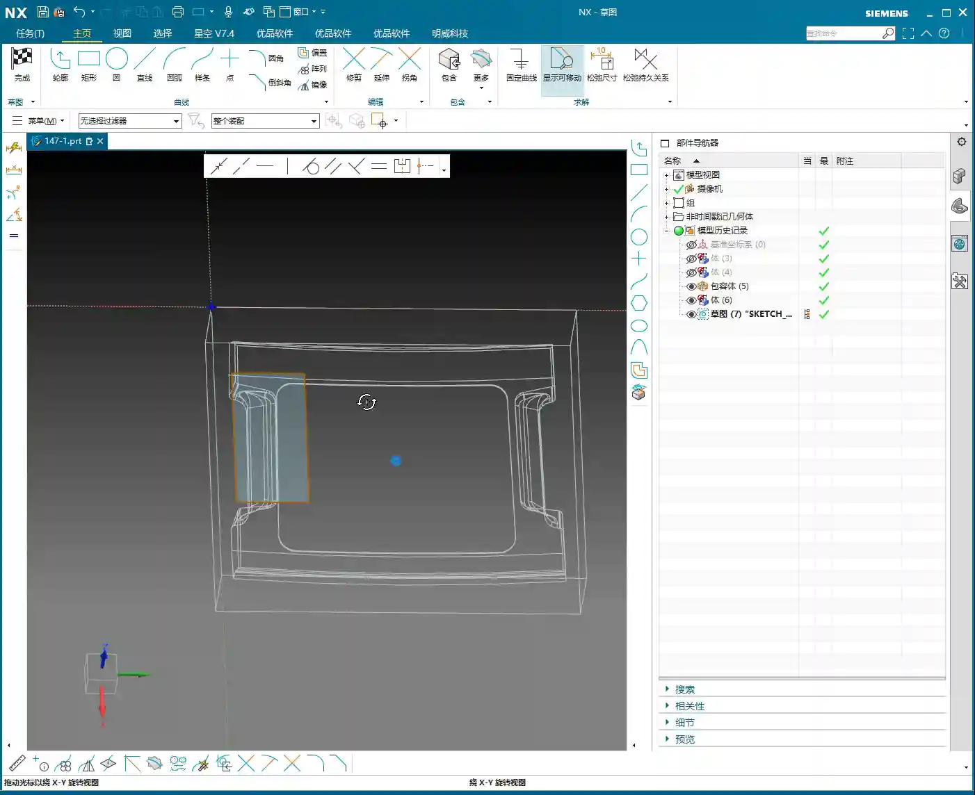
    Many newcomers rush to open Siemens NX for modeling and programming as soon as they get the drawing. This is a huge mistake! Do you know what I emphasize most? Analyze, analyze, and then analyze again!

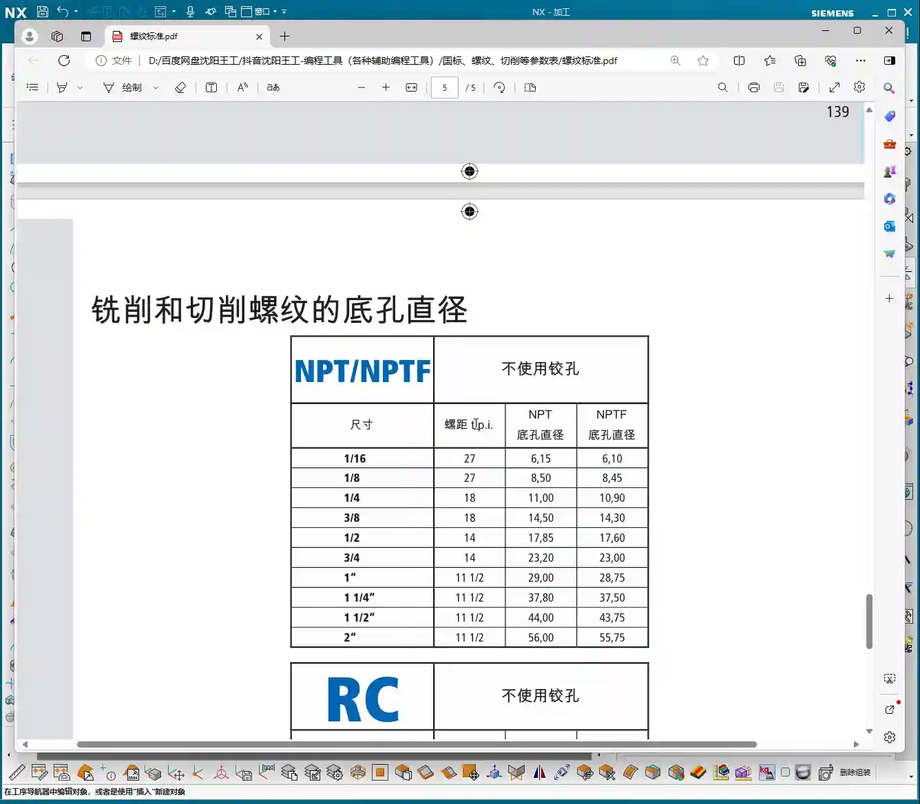
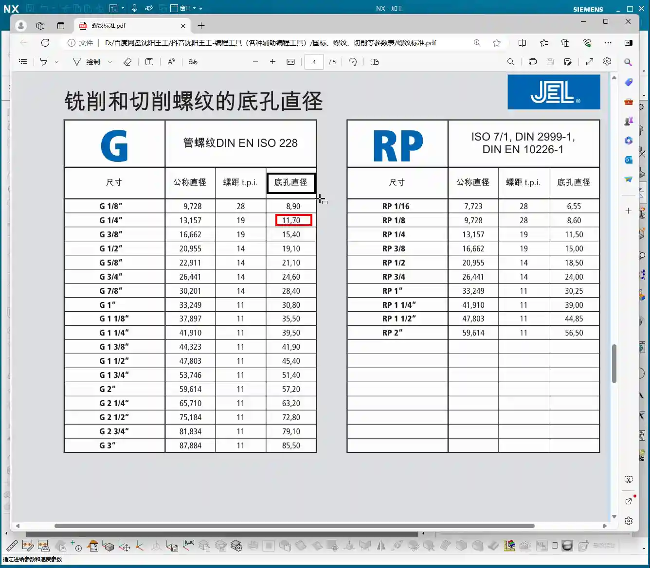
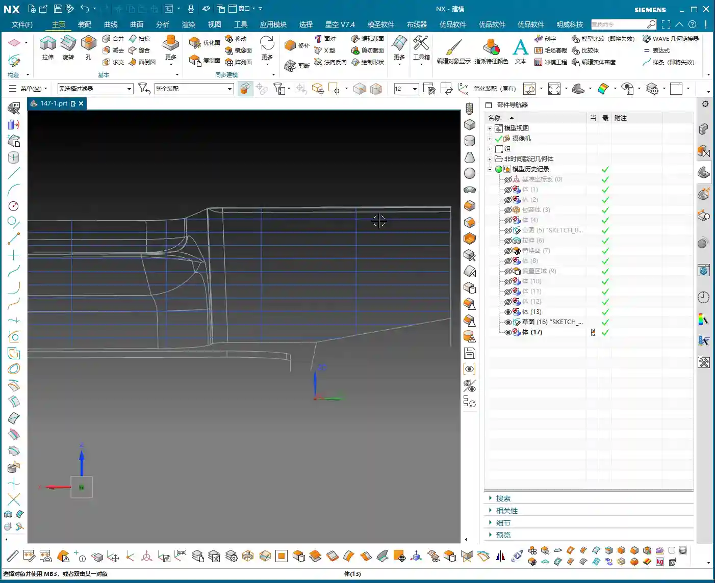
    • Dimensional Inspection: Use Siemens NX’s analysis tools to clearly understand the part’s overall and critical dimensions. For complex surfaces, what’s the slope? What’s the radius of the internal fillets? These are fundamental factors that determine your tool selection and machining strategy.
    • Clamping/Fixturing Plan: How will this part be Clamping or Fixturing? Will you use clamps or a vise? Which areas can be clamped without interfering with machining, while also ensuring rigidity? Which face will be machined first, and which second? This dictates the entire sequence of your machining processes. One wrong step, and you’re in trouble; you could even scrap the part!
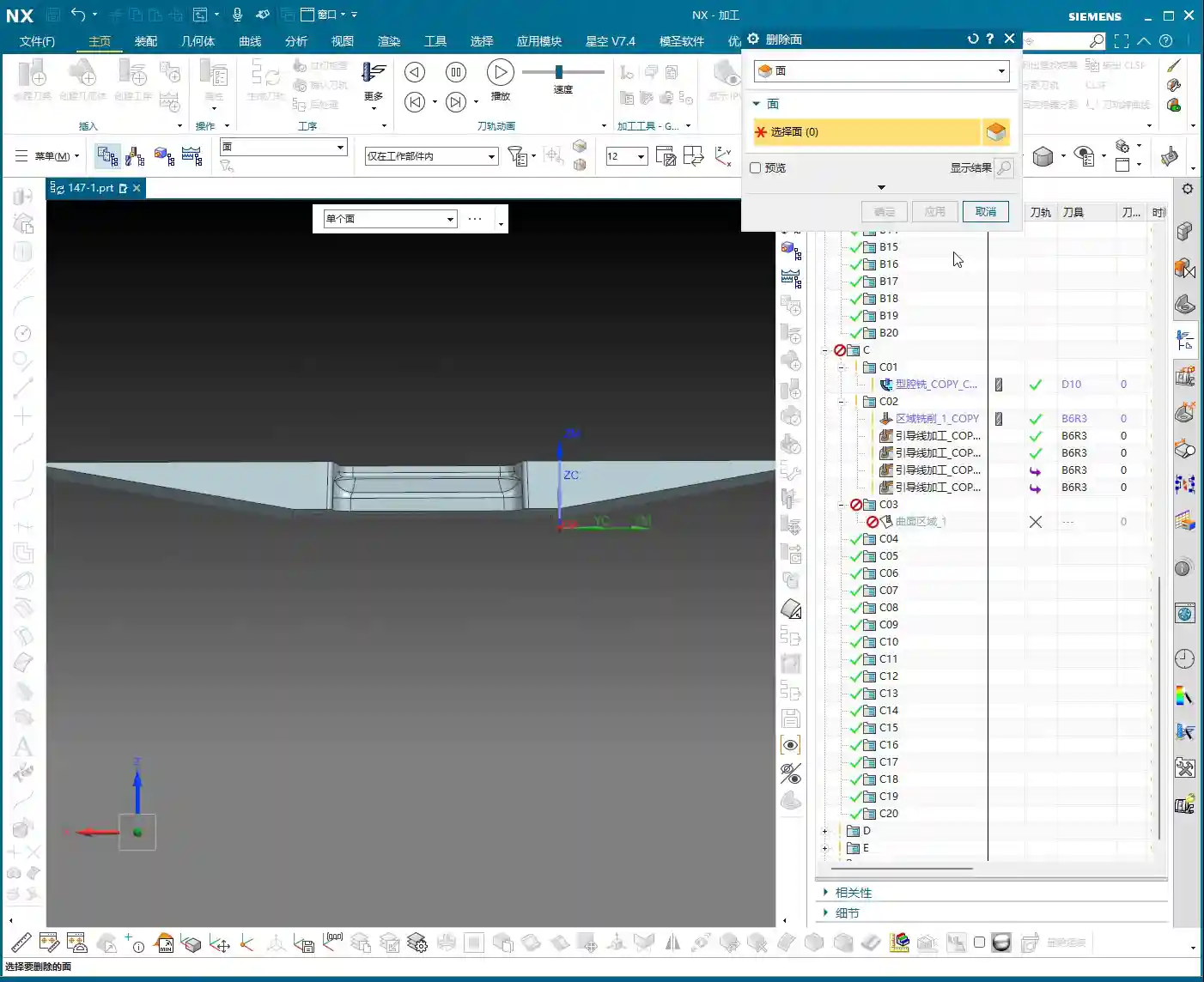
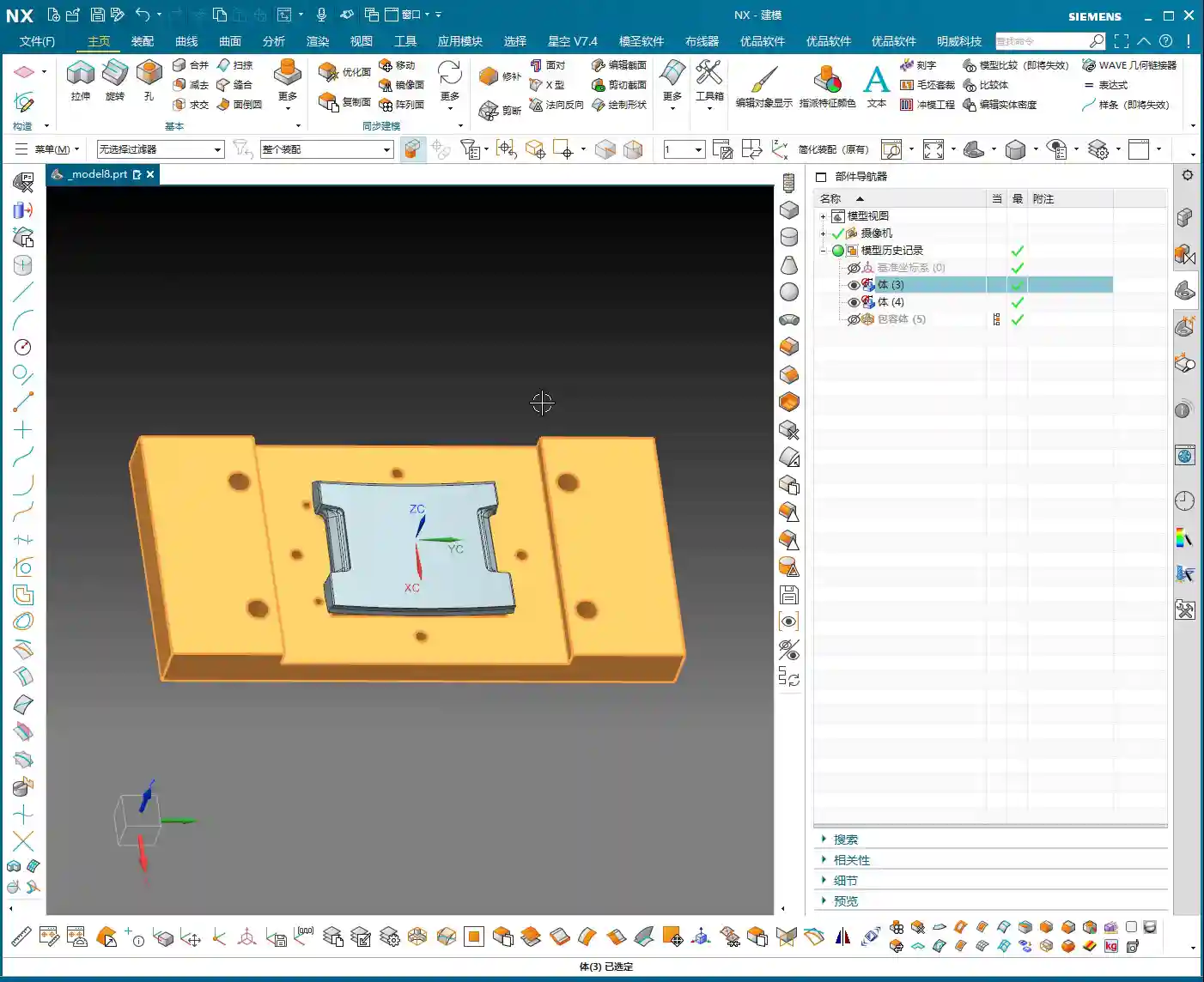
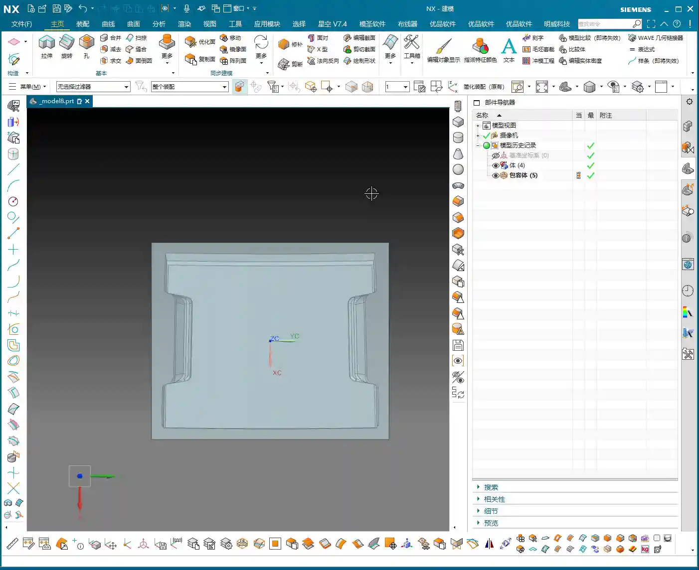
    • Blank Comparison: This is paramount! Don’t just look at the 3D model; inspect the physical blank! Is it a casting, a forging, or raw bar stock? Do its dimensions match our expectations? How much stock allowance is there? If you program for 5 mm (approx. 0.2 inch) of stock, but the actual blank has 10 mm (approx. 0.4 inch), you’re headed for serious trouble! I’ve seen too many cases of scrapped tools and crashed parts because the blank wasn’t properly measured. So, before programming, always compare against the actual blank. That’s real-world experience.

    The ‘Cosmic Shift’ of Siemens NX Programming Commands – Simplifying Complexity

    We’ve covered over 150 lessons, learning dozens, even hundreds, of Siemens NX programming commands. Does that sound overwhelming? In practice, these commands, despite their variations, boil down to just a few main categories. The core principles remain constant!

    Six Core Machining Strategies to Master Any Job!

    To summarize, all the commands we’ve learned can essentially be grouped into these six core machining approaches:

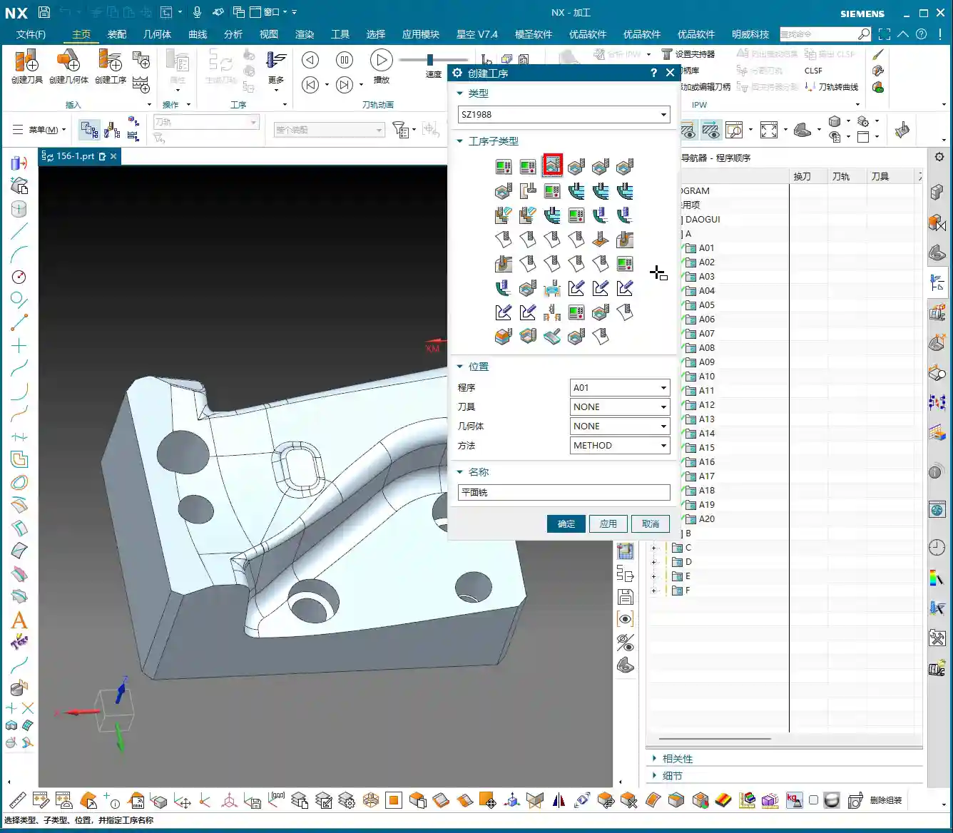
    1. Floor/Bottom Milling: Primarily used for roughing or finishing flat bottoms or planar areas. Don’t underestimate its simplicity; used correctly, it’s highly efficient.
    2. Planar Milling: This broad category includes many sub-commands, but their core purpose is machining flat surfaces. Whether it’s cleaning up planes, side walls, or grooves, the principle is largely the same.
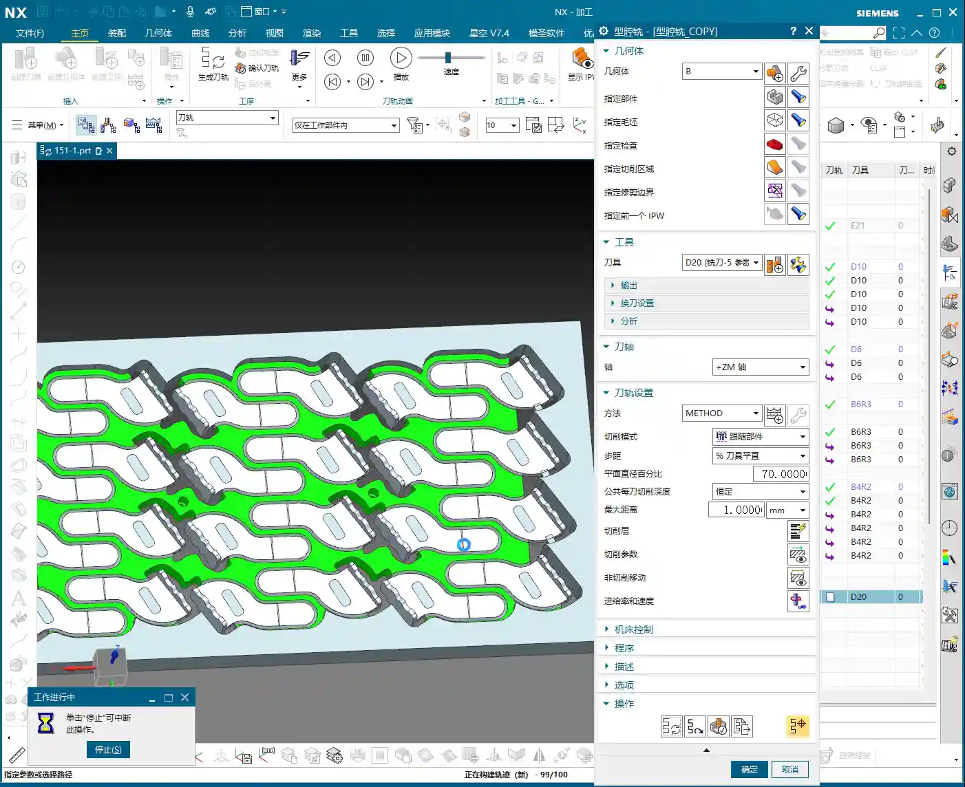
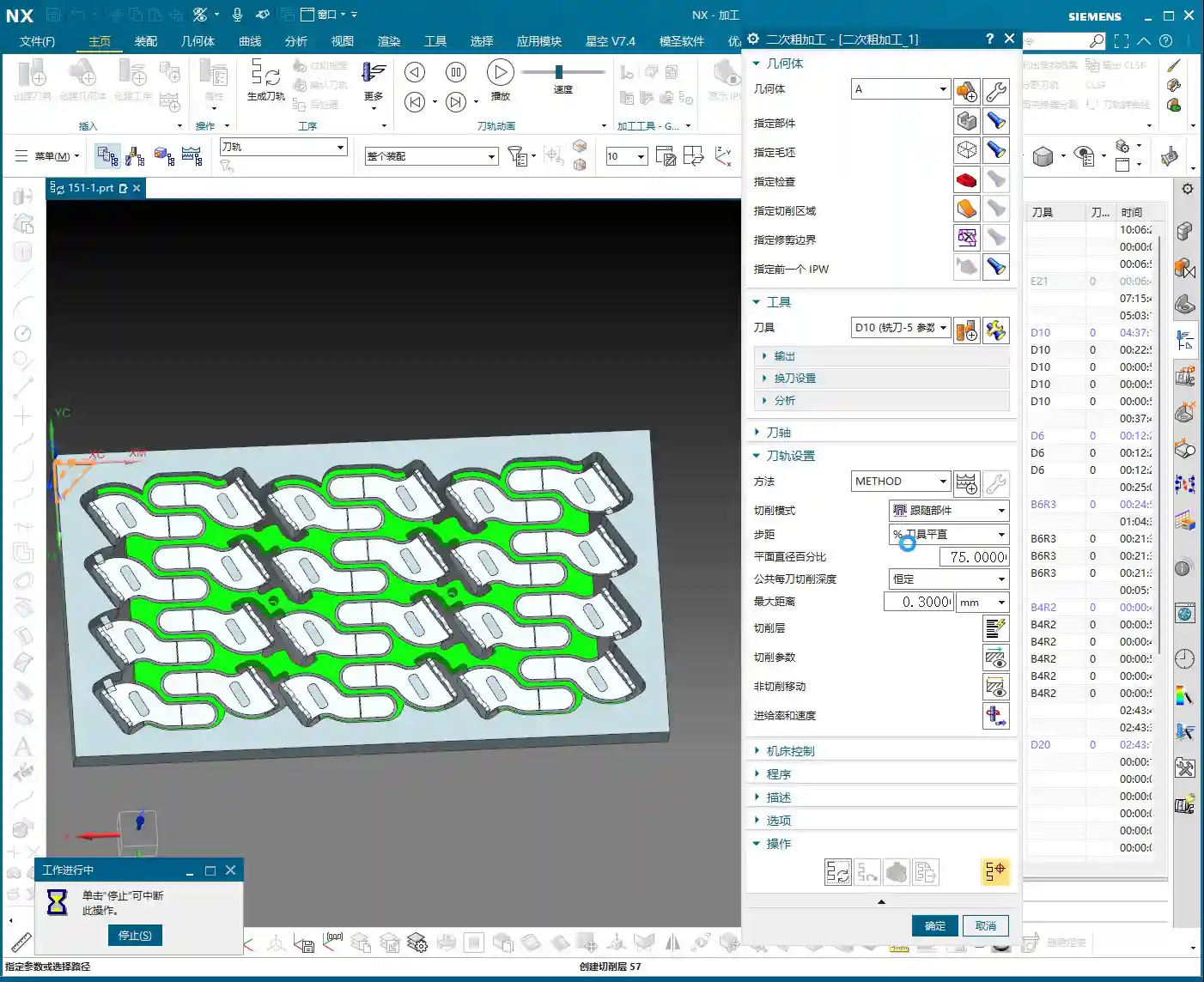
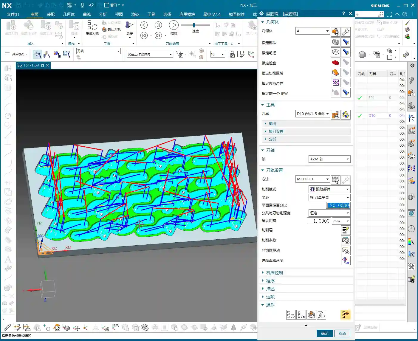
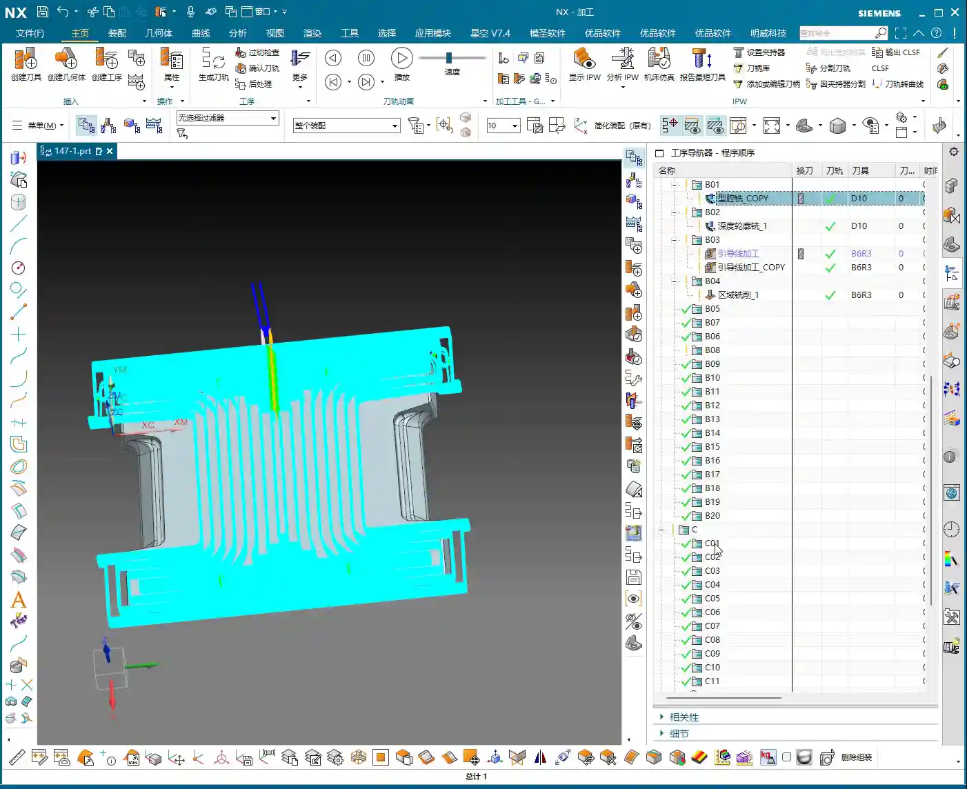
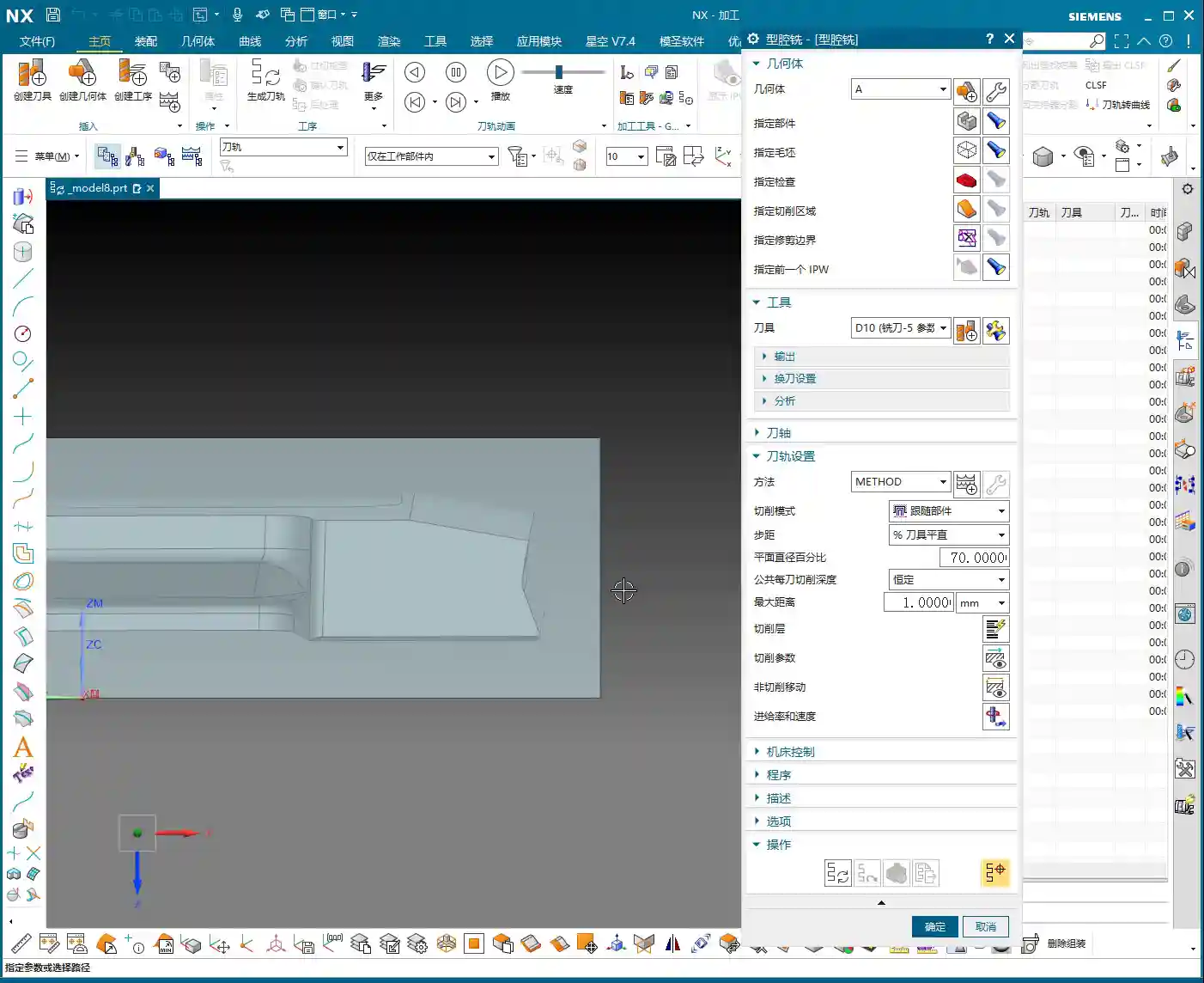
    3. Cavity Milling: Used for processing internal cavities of various shapes. This is our primary strategy for Roughing! Remember, be aggressive with Roughing, prioritize efficiency, but don’t damage the part.
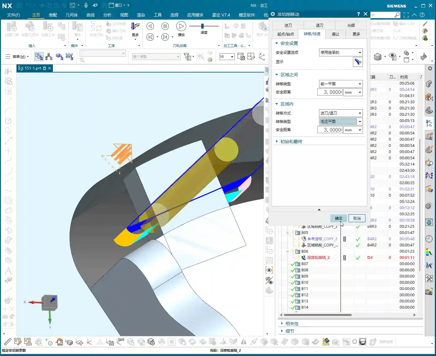
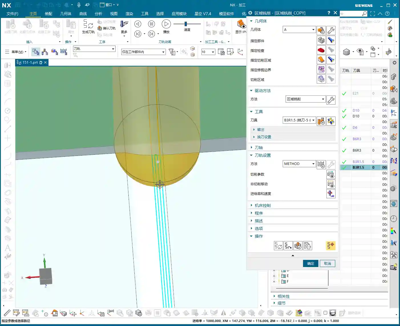
    4. Deep Helical Milling / Side Wall Finishing: For machining side walls in deep cavities and steep regions, deep helical cutting offers high efficiency and stable tool engagement. Side wall finishing is crucial for ensuring surface finish during the Finishing pass.
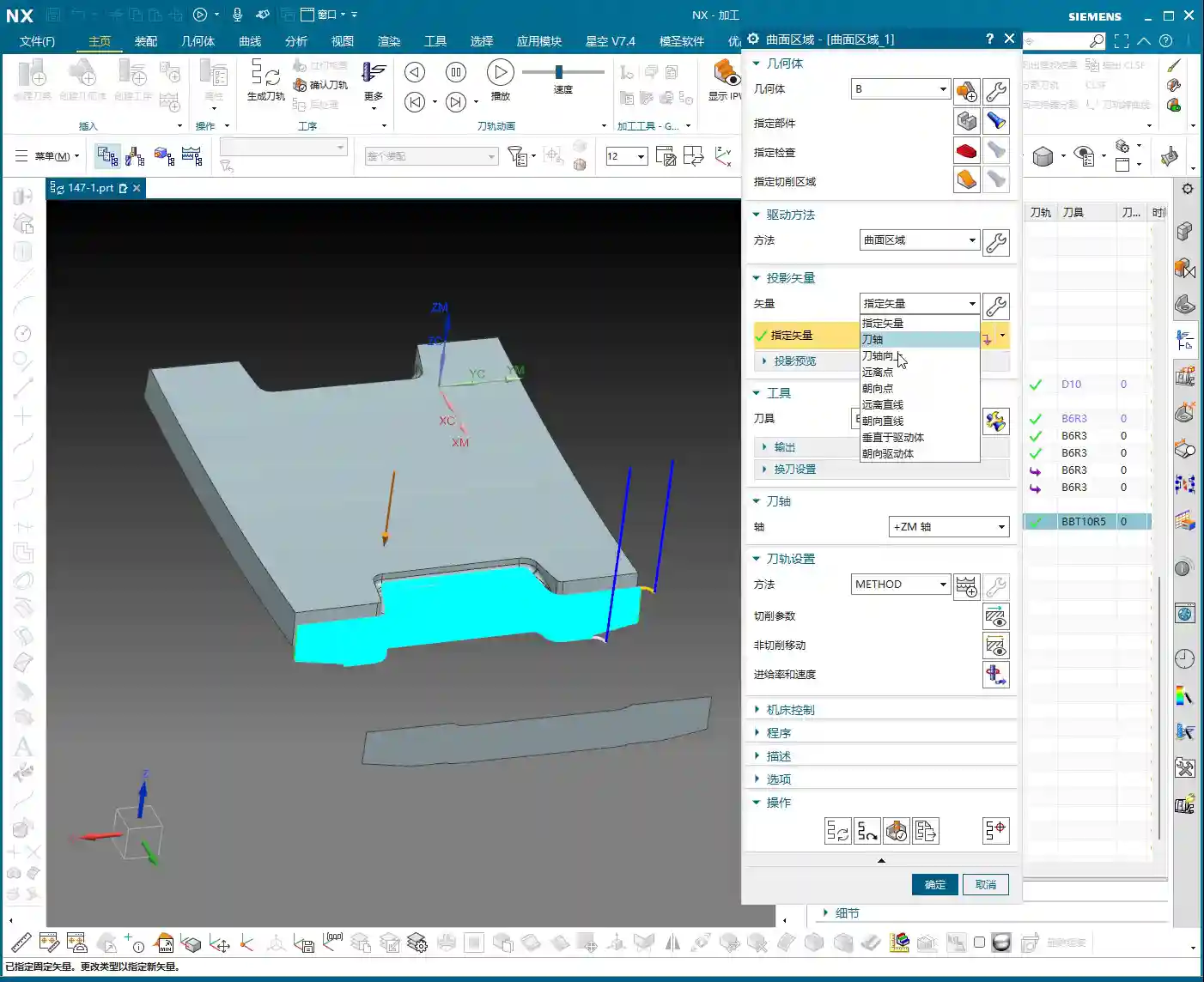
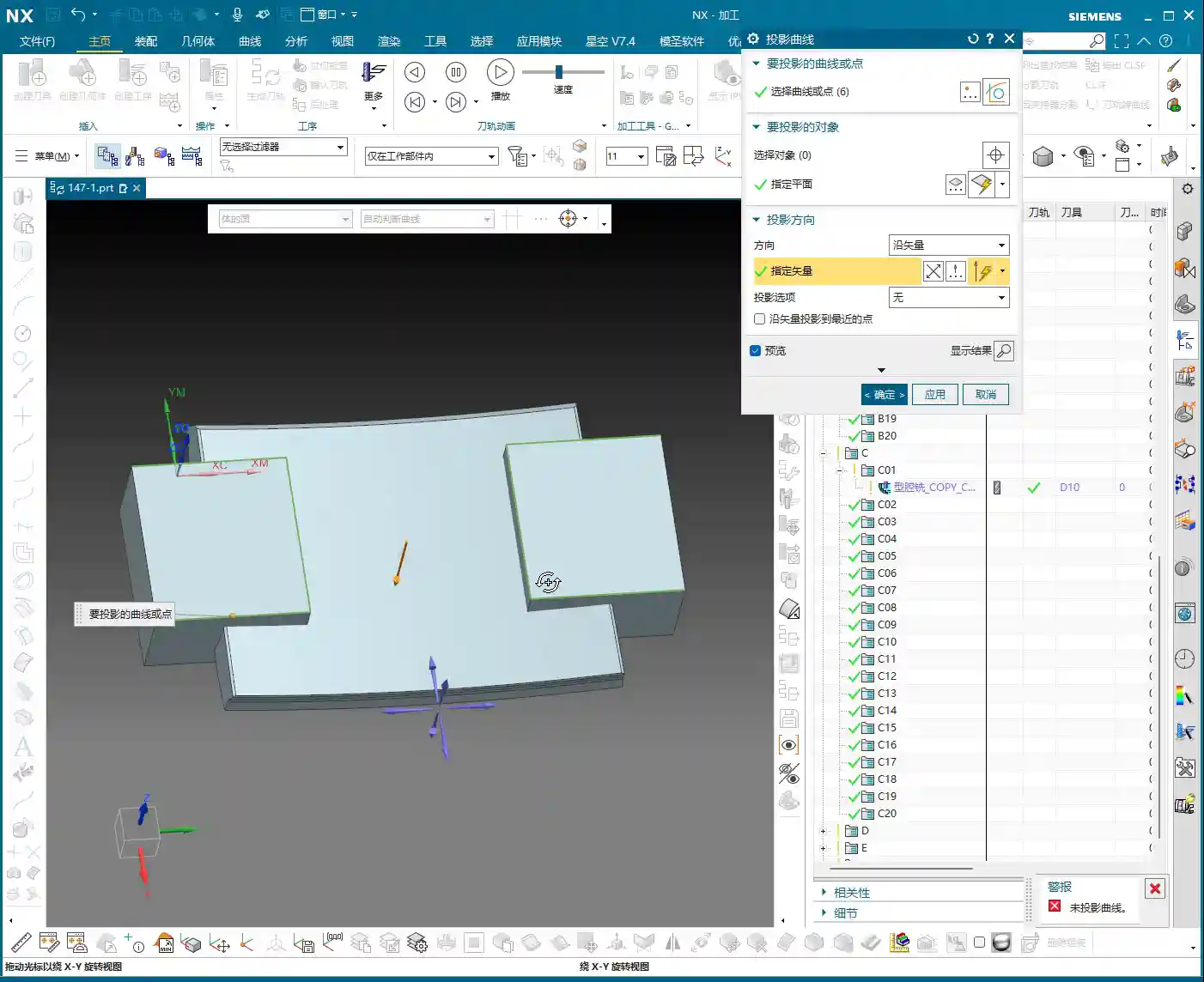
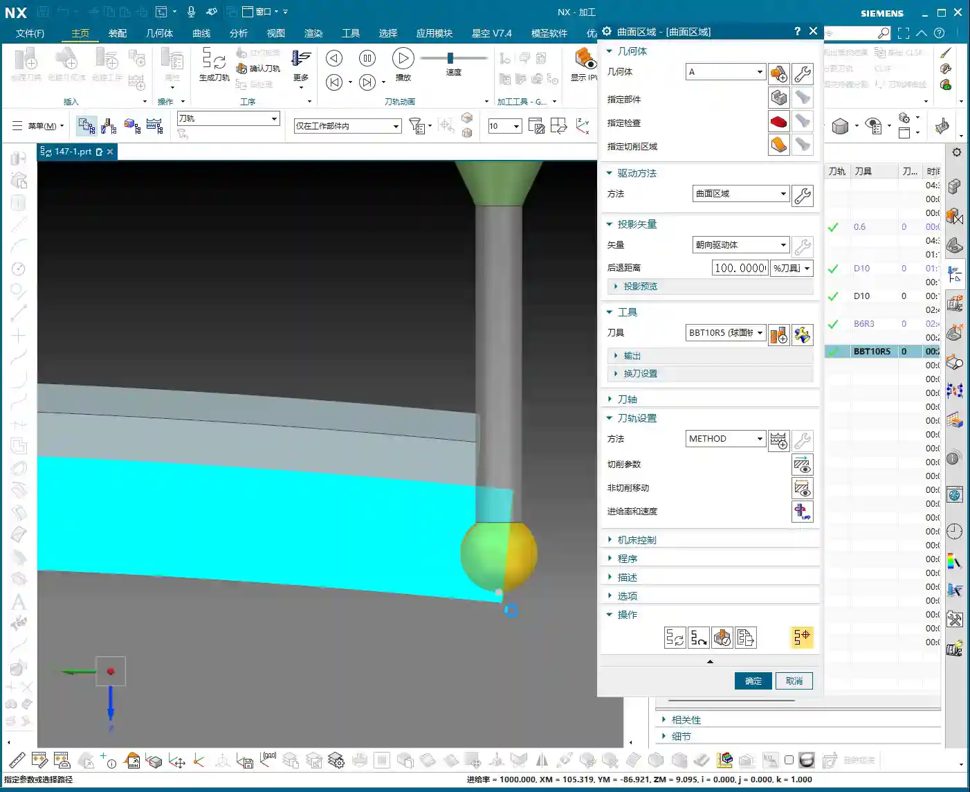
    5. Fixed-Axis Milling: This includes commands driven along curves or from points to surfaces. They are powerful tools for Finishing pass complex surfaces. You need to know when to use “curve-driven” and when to use “surface-driven” — that comes with experience.
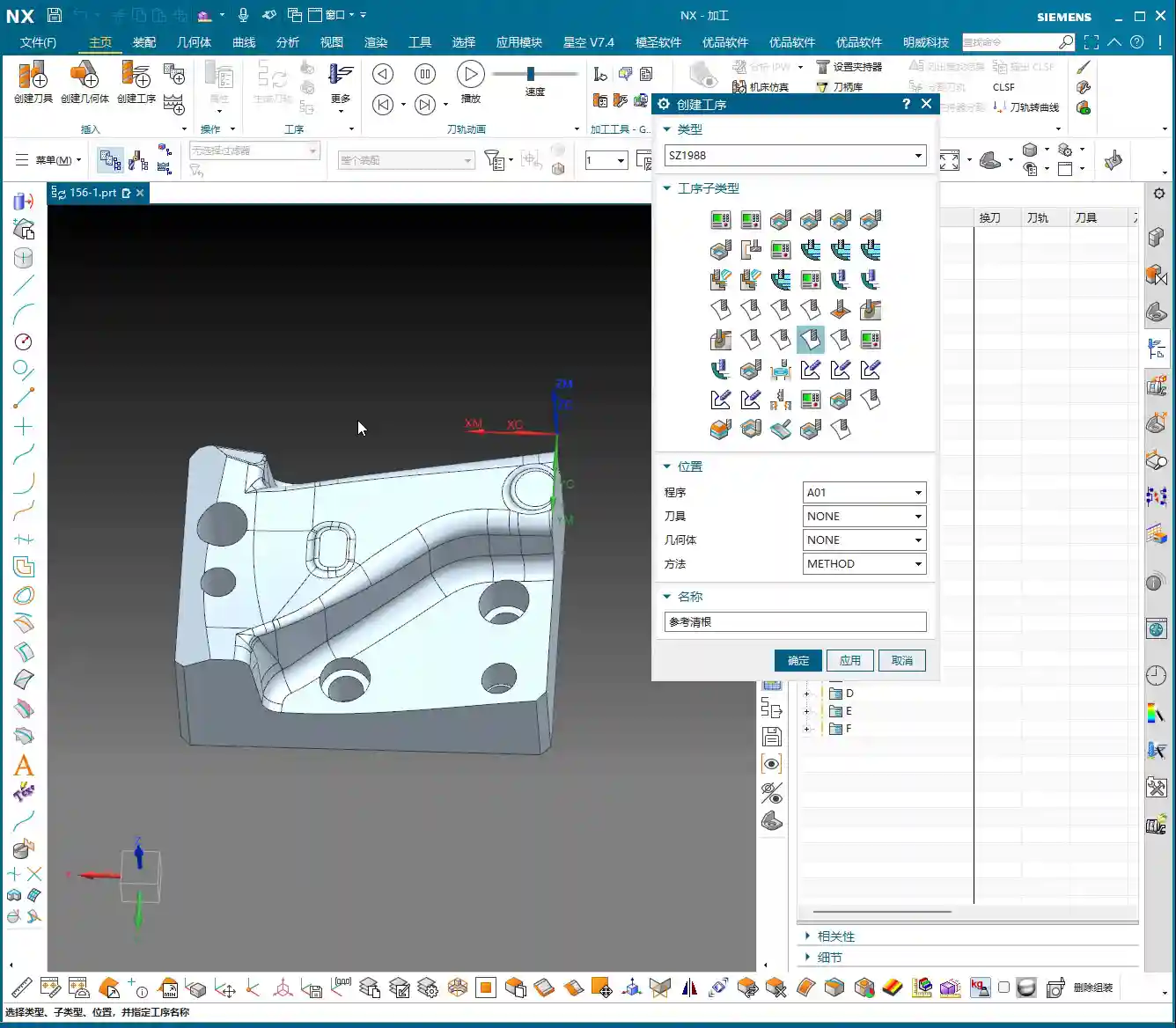
    6. Corner Cleanup / Rest Milling: This is the final step, using smaller tools to clean out corners and remove residual material that larger tools couldn’t reach, ensuring the part’s final accuracy and quality.

    Don’t be intimidated by the number of commands. The machining process for most parts is just a combination of these main categories. Understand their applicable scenarios and respective pros and cons, and you’ll be able to apply them broadly to handle any complex part.

    Practical Process Flow: Master Wang’s Programming ‘Playbook’

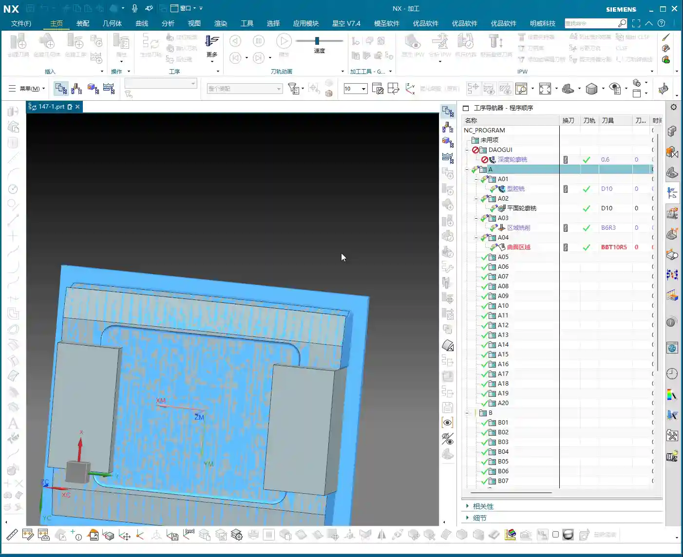
    For a part from raw blank to finished product, our typical Siemens NX programming workflow generally follows this pattern:

    1. Roughing: Rapid ‘Material Removal’

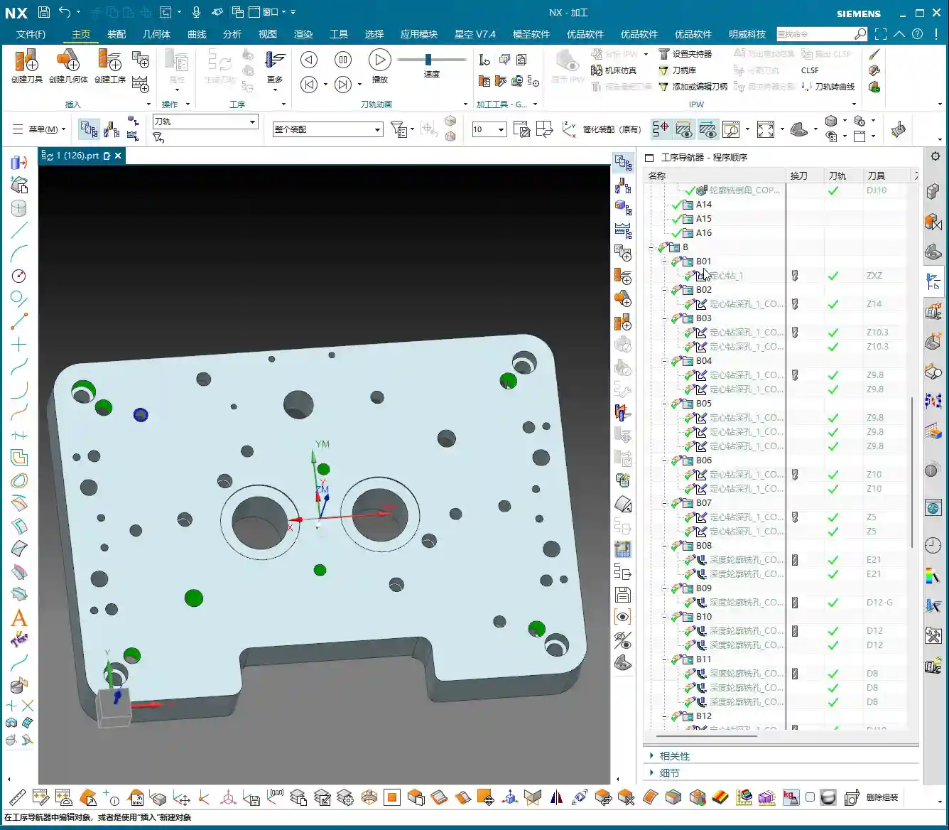
    No matter how complex the part, the first step is Roughing. We typically choose Cavity Milling, using large tools and high feed rates to rapidly remove most of the stock allowance.
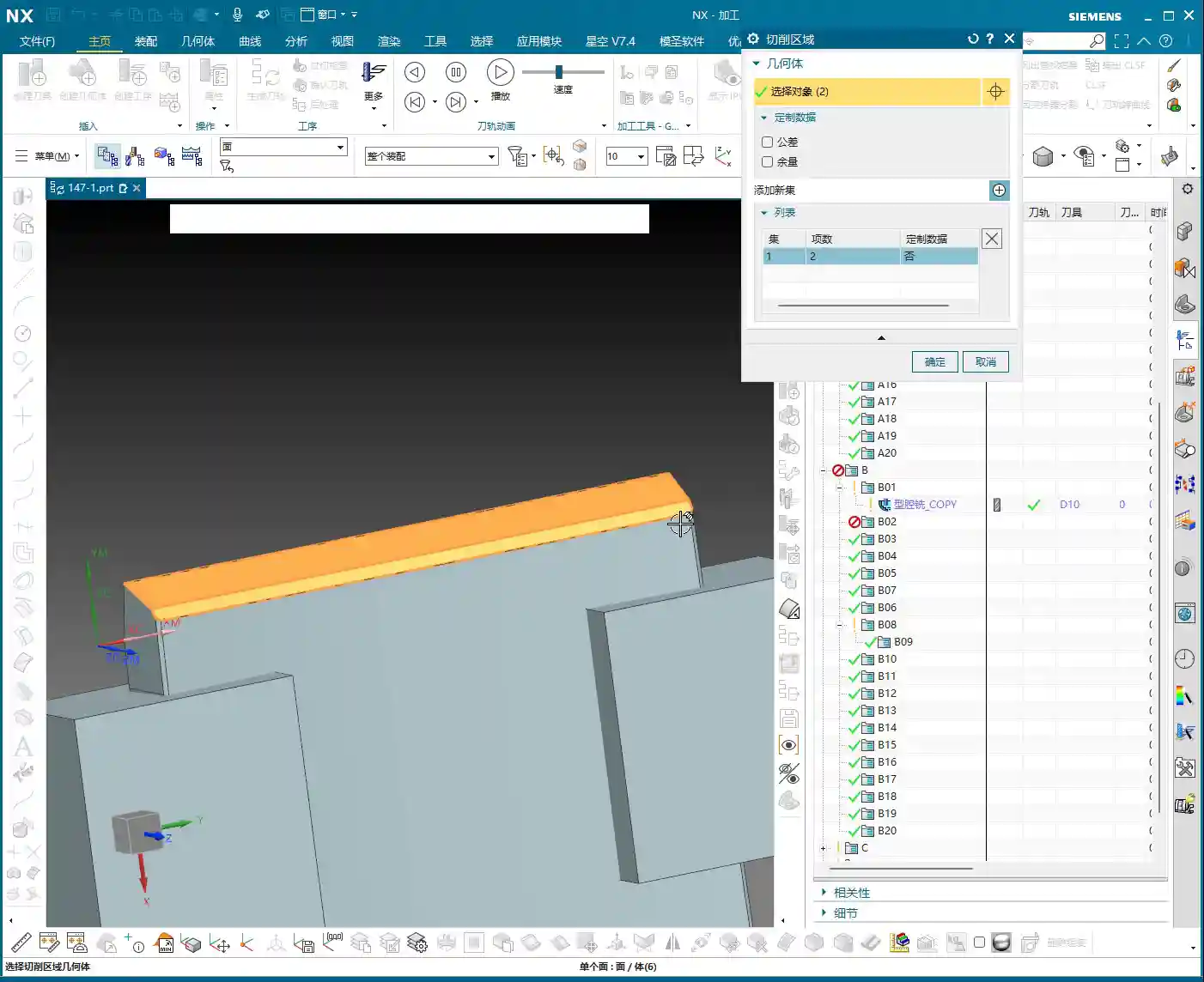
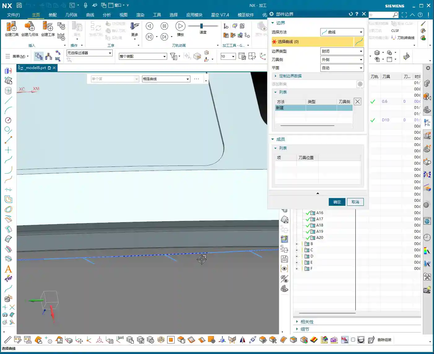
    Listen up, during Roughing, you absolutely must define boundaries around any holes or slots that shouldn’t be touched! Otherwise, the tool will plunge into empty space, leading to air cutting, which not only reduces efficiency but can also damage the tool. Don’t just trust the pretty toolpath simulations; the actual cutting sparks and sounds on the machine don’t lie!

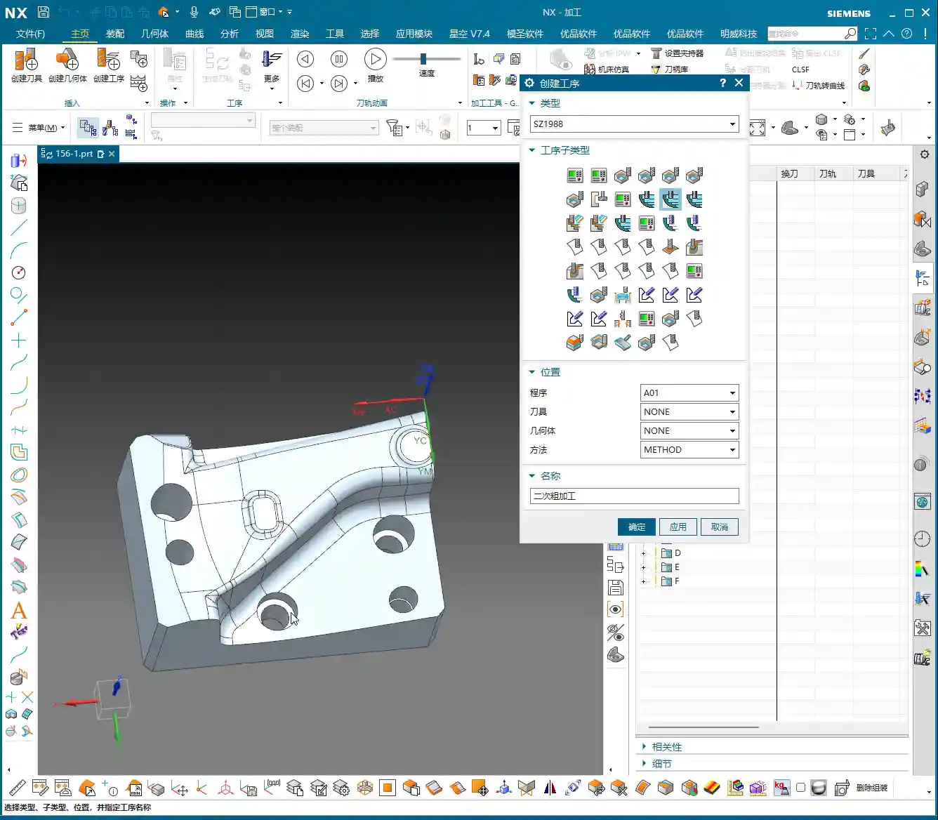
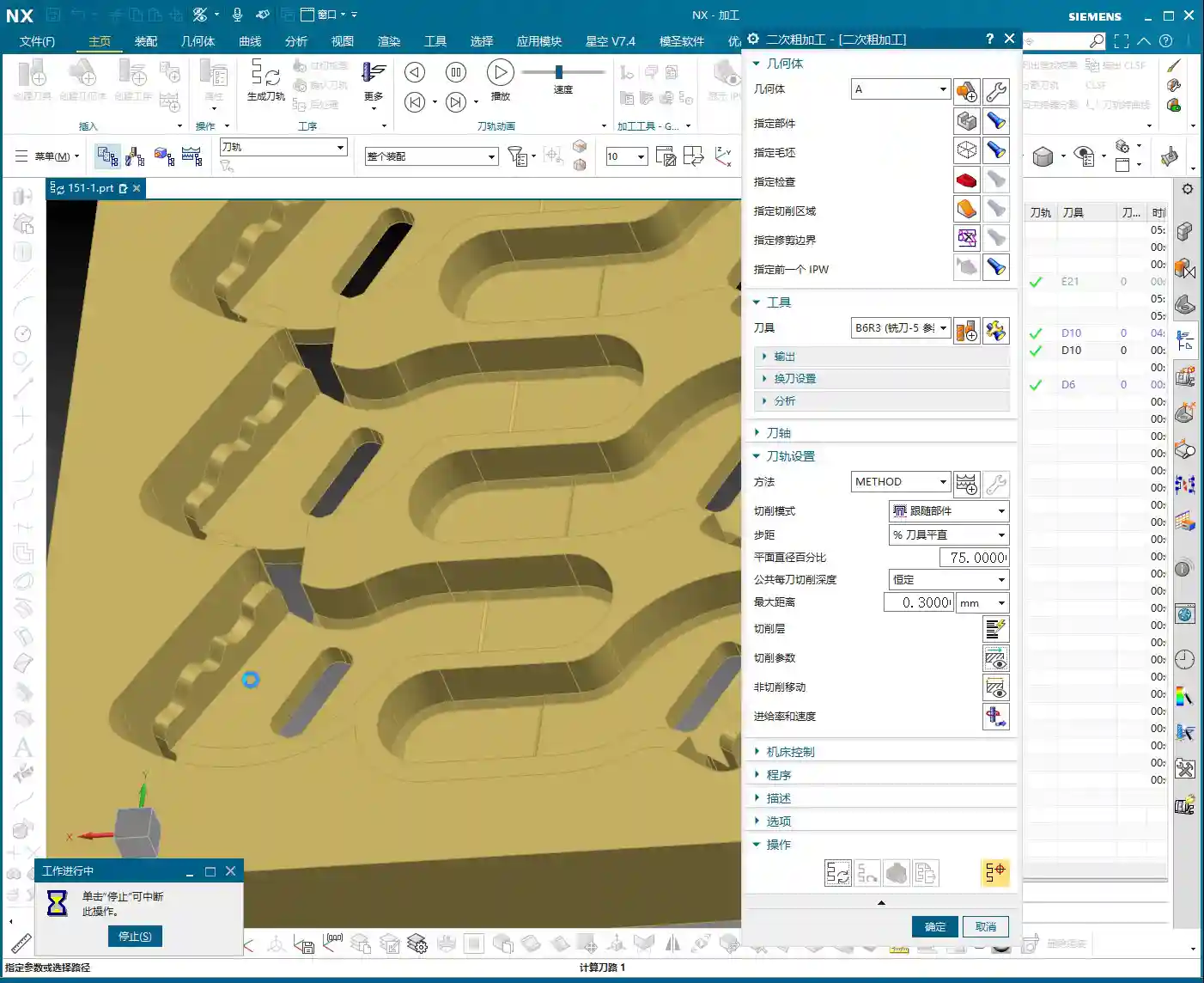
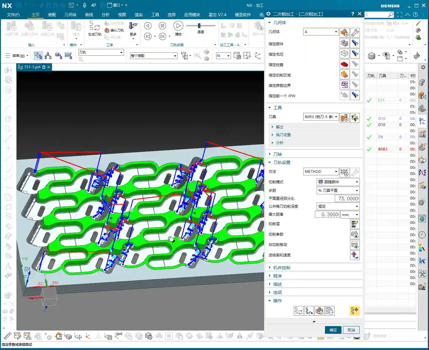
    2. Semi-Roughing / Semi-Finishing: Paving the Way for Finishing

    After Roughing, if the part has large internal fillet radii or still has significant stock allowance, we typically perform a Semi-Roughing pass. This uses a slightly smaller tool than for Roughing to remove some of the remaining material, reducing the load on the subsequent Finishing pass tools and ensuring greater stability during finishing. It’s like building a house: after laying the foundation, you create a rough structure before moving on to the final interior finishes.

    3. Finishing: Surface Quality and Accuracy

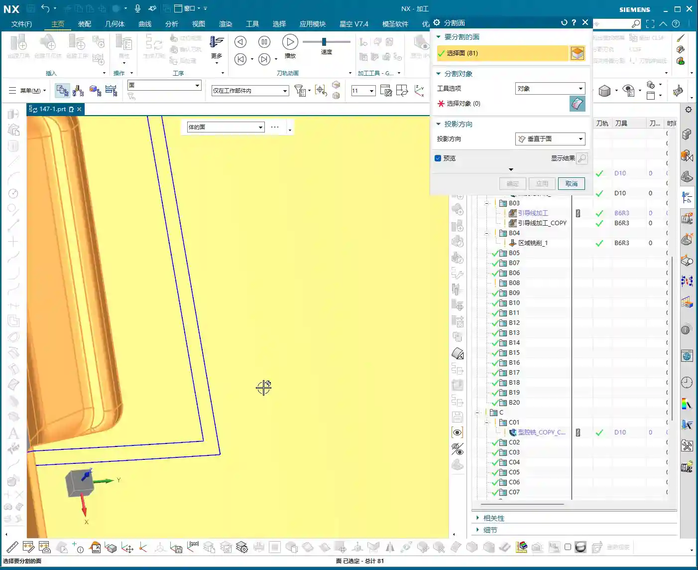
    Finishing is where your true skill is tested. Here, your choices must be based on the part’s geometric features:

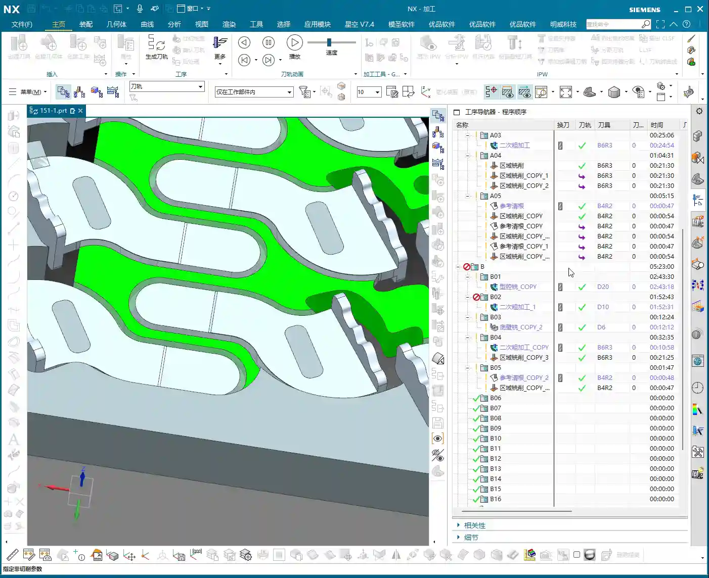
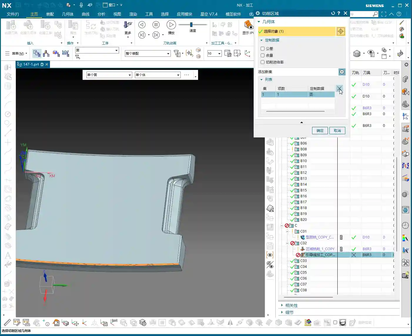
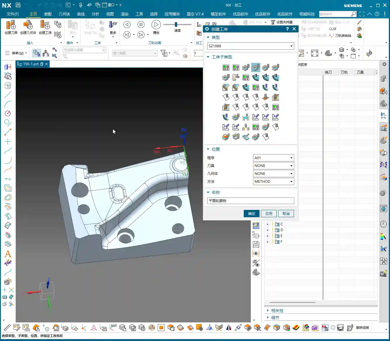
    • Side Wall Finishing: For relatively shallow side walls, we can use Area Milling; for steep regions (e.g., slopes over 45 degrees), you’ll need to use Deep Helical Milling or other machining strategies for efficient regions. Remember, for steep areas, use appropriate tools and toolpath strategies to avoid unstable cutting and surface marks.
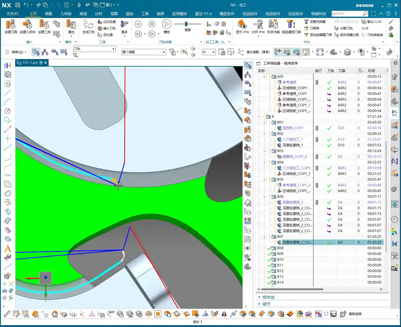
    • Contour Milling: For certain sloped surfaces, you can first perform Contour Milling. A common approach is to contour first, then finish. The machining sequence for these areas can be flexibly adjusted based on the part geometry and accuracy requirements.

    During the Finishing pass stage, you must also pay close attention to tool Chatter and wear. For areas requiring high precision, the tool condition must be excellent, and cutting parameters must be stable.

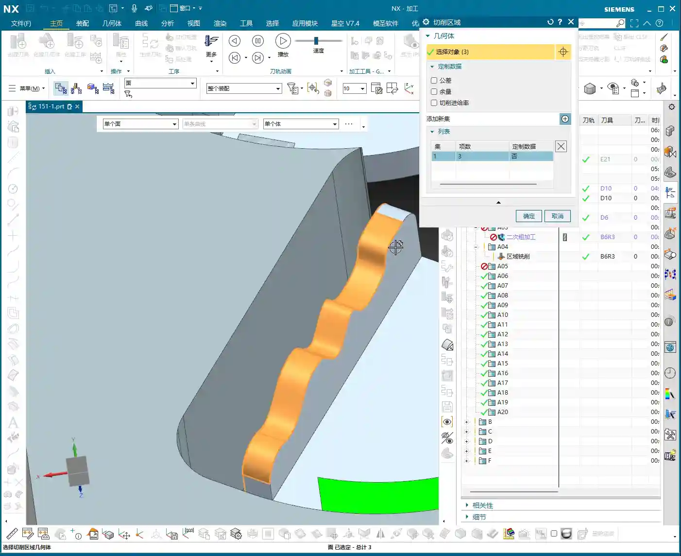
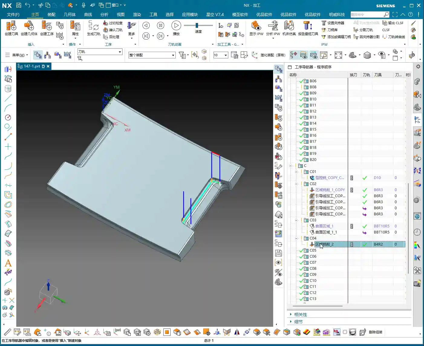
    4. Corner Cleanup / Rest Milling: The Perfect Finish

    Once most surfaces have undergone the Finishing pass, the final step is Corner Cleanup and Rest Milling. Use smaller tools, such as ball end mills or corner radius end mills, to clean out internal corners and residual material that larger tools couldn’t reach. While this is a finishing touch, it’s extremely critical, directly impacting the part’s final quality and assembly performance.

    Master Wang’s Heart-to-Heart: Practical Experience Sharing

    Lads, let me tell you honestly: theoretical knowledge is the foundation, but true skill comes from hands-on practice.

    Don’t Be Intimidated by the Number of Commands; Grasp the Core Principles

    Siemens NX has many commands, but most are optimizations for different scenarios, and their core concepts are interconnected. If you practice for an hour every day, spend some time studying, and stick with it—really delve into the lessons we’ve taught, all 150+ of them—you’ll be able to program most parts. Initially, you can emulate existing programs, see how I’ve programmed them, understand the underlying thought process, then modify them yourself, and eventually program from scratch. That’s how you make rapid progress.

    Just Starting Out? Don’t Expect to Tackle 5-Axis Right Away

    In today’s programming roles, many entry-level tasks involve relatively simple parts, such as drilling holes, milling slots, Face Milling flat surfaces, and simple contours. Complex 5-axis simultaneous machining, Fixed-Axis Milling, and even Cavity Milling or Deep Helical Milling are rarely used initially. This doesn’t mean they’re not important; it means you need to start with the basics. Master foundational skills like Floor/Bottom Milling, Planar Milling, drilling, and hole milling, become efficient at them, and then you can gradually move on to more complex work.

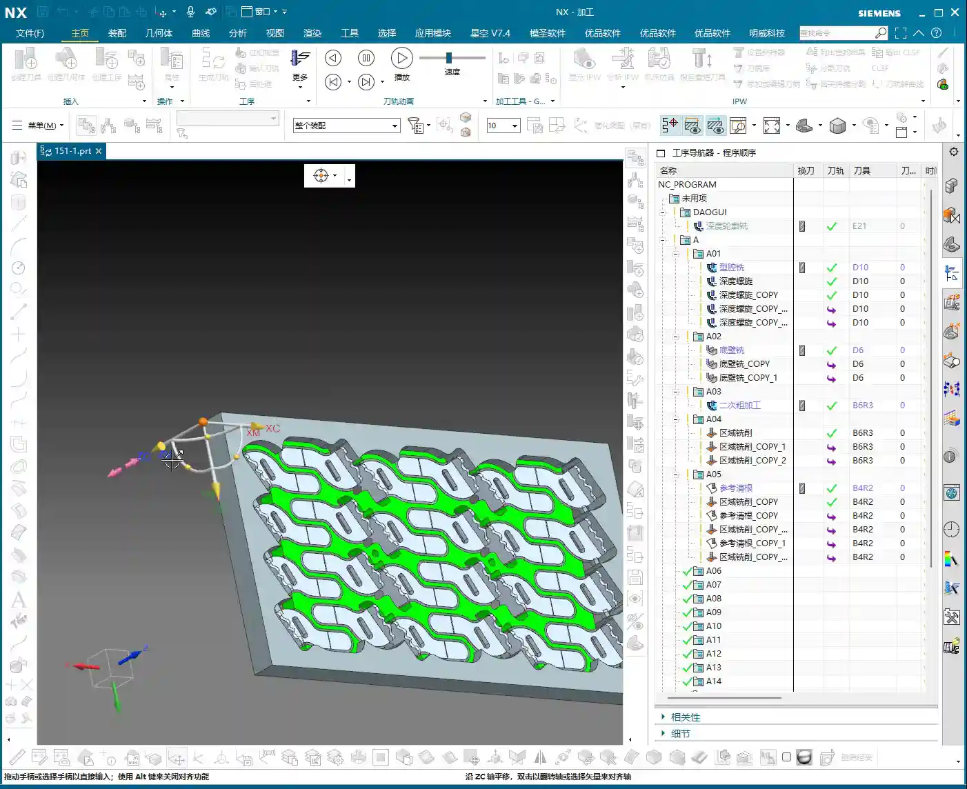
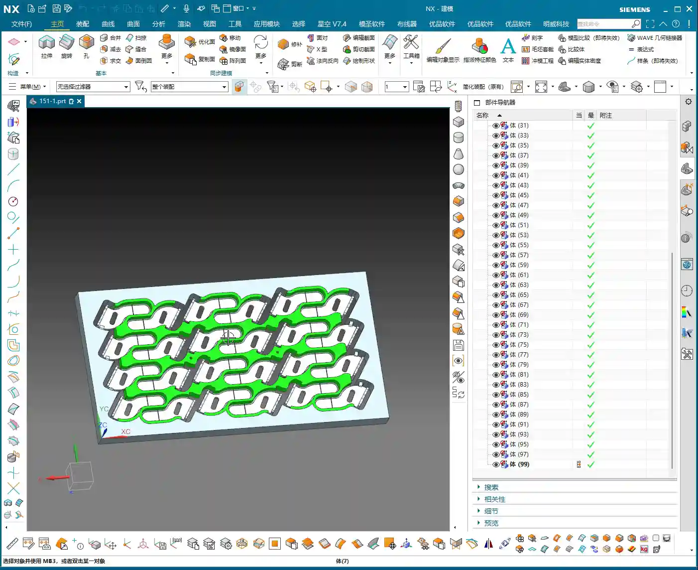
    In fact, for many companies, the primary job of a programmer isn’t high-precision complex surfacing, but rather nesting and layout optimization. They use these basic Siemens NX commands, but the focus is on maximizing material utilization and enabling rapid batch production. That’s another level of technical skill entirely. So, you need to understand that learning technology requires a comprehensive approach, combined with practical application.

    Tool Selection and Process Planning: Paramount Importance!

    Which tool to select? What Depth of Cut (DOC) or Stepdown to use? These are more critical than the programming commands themselves! A tool’s material, coating, and geometry determine the cutting efficiency and quality. For the same part, using different tools and process plans will yield vastly different results. Let me tell you, I can control machining accuracy to ±0.005 mm (approx. ±0.0002 inch), not just by simple command operations, but by a deep understanding of tools, materials, and machine characteristics, combined with process compensation. These are things you won’t learn from textbooks.

    Summary: Pitfall Avoidance Guide

    Finally, here are a few ‘pitfall avoidance’ tips that Old Wang has gathered from years of hands-on experience in the field:

    1. Pitfall One: Neglecting Part and Blank Analysis. Don’t rush into programming as soon as you get the drawing. First, use a tape measure, calipers, or even your naked eye to ‘read’ the part and the blank. If you don’t compare against the blank and just dive in, you’ll run into serious problems sooner or later.
    2. Pitfall Two: Blindly Trusting Software Simulation While Ignoring Cutting Sparks. No matter how beautiful the Siemens NX toolpath simulation looks, you must also consider the actual cutting sound, sparks, and chip evacuation to determine if the process is appropriate. Simulation is theory; the shop floor is practice.
    3. Pitfall Three: Only Learning Commands, Not Practicing Actual Operation. Programming is like driving; you can memorize all the traffic laws, but without hands-on practice, you won’t be able to drive. Practice more, think more, and summarize more.
    4. Pitfall Four: Having Only a Superficial Understanding of Material Properties. Aluminum, steel, titanium alloys, high-temperature nickel-based alloys—their cutting characteristics and heat treatment distortion tendencies are completely different. Without understanding the materials, you’ll encounter all sorts of unexpected problems during machining.
    5. Pitfall Five: Underestimating Fixture Design and Clamping Strategies. A good fixture is the foundation for high-precision machining. Unstable Clamping or Fixturing renders everything else useless. Don’t cut corners on fixtures for the sake of convenience.
    6. Pitfall Six: Ignoring Machine Accuracy and Error Compensation. No machine tool is perfect. Learning to utilize its characteristics and compensate for errors by adjusting process parameters is key to improving accuracy.
    7. Pitfall Seven: Disregarding Cost and Efficiency. Our ultimate goal in this line of work is to create value for the company. How to complete a task in the shortest time, with minimal tool wear, all while ensuring quality, is a question every excellent programmer must consider. This directly impacts a product’s market competitiveness and can even determine if an industrial product keyword will rank prominently in search engine results!

    👤 About the Author:
    The author is a veteran CNC machining professional with 15 years of industry experience, specializing in UG NX programming. This article is an original work representing personal practical insights.

    ⚠️ Copyright Notice: Unauthorized reproduction or distribution without prior communication is strictly prohibited.

  • Master Wang’s Practical Guide: The Exclusive Secret to Imperial Thread Pitch Calculation in Siemens

    📝 Key Takeaways:

    Imperial Threads: Do NOT Follow Metric “Routines”!

    [VIDEO_HERE]

    Introduction: Thread Machining is All About Experience

    Imperial Threads: A Hidden Practical Challenge

    Hello everyone, I’m Master Wang. Today, let’s cut the fluff and get straight to the point: threads. Especially imperial threads. Don’t let those few letters and numbers on the blueprint fool you; if you don’t truly understand their “temperament,” you’re in for a world of trouble. Pipe threads, American threads—there’s a whole bunch that can make your head spin. But at their core, it all comes down to one thing: the “pitch.” How do you calculate the pitch? And what size should the pilot hole be? Today, we’ll break it all down, and I guarantee you’ll be able to put it into practice immediately!

    Unveiling the “Temperament” of Imperial Threads

    Why You Can’t Simply Apply Metric Thinking to Imperial Threads

    Many newcomers, when they see threads, take it for granted, thinking that for metric threads like M8 or M10, the pitch is simply 1.25 or 1.5 mm – straightforward. But imperial threads don’t play that game! They use “Threads Per Inch” (TPI), which is completely different from our accustomed millimeter pitch. If you try to apply metric rules directly to imperial threads, you’ll end up with tool breakage at best, or a scrapped part at worst—and that’s real money down the drain!

    The Master Machinist’s “Toolbox”: Thread Standard Charts

    What you can’t learn from books, you’ll find in practical application. I’ve compiled my own set of thread standard charts, which include various national and American standards, and even non-standard data I’ve gathered from years of machining experience. You’ll find them all in my NX course. Look for “National Standard Threads” in the programming tools, and within that, a “Cutting Parameters and Other Data” table. Open this “Thread Standards” table, and you’ll see it’s packed with invaluable resources! I highly recommend you download it, print it out, and keep it by your machine. Refer to it often; it’s a hundred times better than random guesswork. It covers metric coarse and fine threads, the American UNC and UNF threads we’re discussing today, and pipe threads like NPT, NPS, and more. Don’t underestimate these tables; they can be a lifesaver in critical situations!

    Practical Calculation: UNC 1/4 Thread Pitch Calculation

    Understanding the Pilot Hole: The 5.1mm Pilot Hole for UNC 1/4

    Let’s take a common example: a blueprint calls for UNC 1/4. Many rookies get confused instantly. What is this? Listen up: UNC stands for Unified National Coarse thread, American standard, and 1/4 refers to its nominal diameter (in inches). What’s the pilot hole size for this thread? Based on my experience and the standard charts, the pilot hole for UNC 1/4 is typically 5.1 millimeters. Grab a 5.1mm drill bit, drill it, and you’re good to go. After drilling, you’ll need to prepare a UNC 1/4 tap for tapping.

    The Core Formula: 25.4 / TPI = Pitch

    Now, here’s the challenge: when tapping on a machine, you need to know the thread’s pitch to set the correct feed rate (F-value). What’s the pitch for UNC 1/4? Its corresponding Threads Per Inch (TPI) is 20. Many might wonder, “How can the pitch be 20 when the pilot hole is only 5.1mm?” Don’t be misled by the numbers; here, 20 means there are 20 threads within one inch of length!

    So, to calculate its pitch in millimeters, we need to use this conversion formula:
    1. Remember this critical constant: 1 inch = 25.4 millimeters.
    2. Pitch = 25.4 millimeters / Threads Per Inch (TPI).

    Plugging in the data for UNC 1/4:
    Pitch = 25.4 / 20 = 1.27 millimeters.
    Got it? It’s that simple!

    NX Programming: Precise F-Value Setting

    Now, let’s return to the NX programming interface. If your spindle speed is set to 100 Revolutions Per Minute (RPM), what should the feed rate (F-value) be?
    In most CNC systems, the F-value during tapping is simply the pitch. So, you can directly input the pitch we calculated: 1.27 (mm/rev). Of course, some systems might require you to input the unit as millimeters/minute. In that case, you’d multiply the pitch by the RPM, for example, 1.27 * 100 = 127 mm/minute. However, for canned threading cycles (like G32, G76, etc.), you typically input the pitch directly, and the system automatically converts it based on the spindle speed.

    Applying the Principle: G Threads and NPT/NPTF

    G 1/4 Thread: 11.7mm Pilot Hole, 19 TPI

    Let’s look at another example with G threads. Take G 1/4, which is typically a pipe thread. What’s its pilot hole size? Checking the chart, we find that the pilot hole for G 1/4 is 11.7 millimeters. Its Threads Per Inch (TPI) is 19.
    So, Pitch = 25.4 / 19 ≈ 1.34 millimeters.
    By the same logic, the F-value should be set to 1.34. Simple, right?

    NPT vs. NPTF: Details Determine Success

    Besides UNC and G threads, you’ll also encounter tapered pipe threads like NPT and NPTF. The calculation principle for these threads is the same: it’s always 25.4 divided by the Threads Per Inch (TPI). For instance, NPT 1/4 has a TPI of 18, so its pitch is 25.4/18 ≈ 1.411mm.
    But here’s a subtle pitfall: there’s a slight difference in the pilot hole diameters between NPT and NPTF threads! Typically, the pilot hole for NPTF will be slightly smaller than for NPT, perhaps by 0.02 to 0.04 millimeters. Don’t underestimate this small difference; it directly impacts the sealing performance of tapered pipe threads. Therefore, never confuse NPT and NPTF. Always strictly follow the blueprint and standards to select the correct pilot hole and tap. Otherwise, you’ll be endlessly reworking parts!

    Summary: Pitfall Avoidance Guide

    Pitfall Avoidance Guide

    1. Understand the Principle, Don’t Just Memorize: The core of imperial threads is “Threads Per Inch” (TPI). Master the formula “25.4 / TPI = Pitch,” and you’ll be able to calculate the pitch for any imperial thread.
    2. Standard Charts Are Your Go-To Guide: The thread standard charts I provide are your most practical tool in the workshop. When encountering an unfamiliar thread, your first reaction should be to check the chart to confirm its TPI and recommended pilot hole.
    3. Pilot Hole Must Be Precise, Tap Must Match: The size of the pilot hole directly impacts tapping quality and tap life. Imperial thread pilot holes cannot be estimated by experience; they must adhere to standards. Furthermore, always select a tap that perfectly matches the thread specification, especially for subtle differences like NPT and NPTF – never mix them up.
    4. NX Programming: F-Value Setting is Key: When programming thread milling or turning in NX or other CAM software, the feed rate (F-value) must be set to the calculated actual pitch (millimeters/revolution), or the equivalent feed speed required by the system. This is fundamental to ensuring thread accuracy and tool safety.
    5. Practice More, Think More: No matter how well you understand the theory, it’s useless if you don’t apply it on the machine. Find more threaded parts to practice with, or draw some threads yourself in NX, simulate the machining process, and clarify the F-value, pilot hole, and tools. Practical application reveals the truth; don’t just rely on software simulations, observe the cutting sparks!

    Remember these points, and machining imperial threads won’t seem so mysterious. The most important things are to calculate the pitch correctly and drill the pilot hole accurately; the rest of the programming will be minor issues. Alright, that concludes today’s lesson. If anything is unclear, or if you need more tutorials and templates, feel free to contact Master Wang!

    👤 About the Author:
    The author is a veteran CNC machining professional with 15 years of industry experience, specializing in UG NX programming. This article is an original work representing personal practical insights.

    ⚠️ Copyright Notice: Unauthorized reproduction or distribution without prior communication is strictly prohibited.

  • NX Guide: 铝件全序编程讲解

    📝 Key Takeaways:

    [VIDEO_HERE]

    👤 About the Author:
    The author is a veteran CNC machining professional with 15 years of industry experience, specializing in UG NX programming. This article is an original work representing personal practical insights.

    ⚠️ Copyright Notice: Unauthorized reproduction or distribution without prior communication is strictly prohibited.

  • Siemens NX Secondary Roughing Programming Masterclass: Master Wang Teaches High-Efficiency Corner Cl

    📝 Key Takeaways:

    NX Secondary Roughing: Master Wang’s Practical Techniques

    Opening: Lingering Issues from the Last Program

    Hello everyone, I’m Master Wang. In our last session, we finished programming the roughing operations for the first side. However, in some areas, the program ran slowly, and the computer lagged a bit. In the workshop, time is money, and a slow program means lost production! So today, we need to address these lingering issues, especially those “unmachined” areas, which are regions that weren’t fully cleaned up.

    Checking and Addressing Residual Stock

    Alright, let’s go back one step and quickly check which areas weren’t fully milled. Listen up: don’t just focus on the large flat surfaces. The real problem spots, where the tool is likely to engage heavily and cause issues, are often the small corners and grooves. I’ve noticed several areas that were “skipped” or “missed,” leaving behind a bit of residual stock. Some areas, especially on the side walls, still look like they have “remnants.”

    • Problem Areas: Found several spots, particularly edges and corners, where small amounts of stock remained after the previous program, looking “unmachined.”
    • Solution Approach: A “Corner Cleanup” operation is needed to remove this residual stock, preparing the part for subsequent finishing passes.

    First Corner Cleanup: Addressing Residuals on the First Side

    For this residual stock, we can simply copy an existing program and make a few parameter adjustments. This is the most efficient method and minimizes errors.

    Program Duplication and Parameter Adjustment

    I’ll directly copy one of our previous programs. Remember, after copying, the first thing you must do is check several key parameters:

    • Connections: Change the connection type from default to “Move” to prevent unnecessary tool lifts and air cuts.
    • Stock: For a corner cleanup operation, set the stock directly to 0. Our goal is to remove all the excess material.

    Tool Entry/Exit Strategy: Avoiding Collision Risks

    As soon as the program ran, I immediately spotted an issue: the tool entry/exit was problematic, preventing the tool from safely entering and retracting. This is one of the most common mistakes made by beginner programmers!

    • Original Problem: The tool entry/exit path was unreasonable, prone to scratching the workpiece or making air cuts.
    • Solution:

      • Change the tool entry/exit method to “Same as Open Area”, allowing the tool to enter and retract in obstacle-free regions.
      • Select “Arc Engage” for the tool entry method, with a radius of 1 millimeter. Arc engagement effectively prevents the tool from plunging directly into the material, reduces impact, protects the tool, and results in a better surface finish.

    Tool Selection and Boundary Handling

    For this corner cleanup, we’ll choose a 10mm flat end mill (Ø10mm). Its size is suitable, allowing it to reach into narrower areas while maintaining sufficient rigidity. A Ø6mm tool might be too weak.

    Next, I noticed that a certain spot might not have been thoroughly cleaned due to the toolpath, which is “not ideal.” However, it’s not a major issue. For the roughing stage, as long as it doesn’t affect subsequent finishing, occasional minor imperfections can be temporarily “overlooked.” We need to learn to prioritize and not get bogged down over-focusing on minute details during roughing; that’s not a good practice.

    Second Side Machining: Efficiency and Strategy

    With the first side done, we need to quickly flip the part and machine the other side. Remember, in the workshop, flipping the part and fixturing are among the biggest time costs, so programs must be correct the first time, minimizing rework.

    Coordinate System Transformation and Program Reuse

    The quickest method is to transform the coordinate system, then copy the existing program and make minor modifications. Most parameters are universal.

    • Blank Geometry Selection: The key is to select the blank geometry as this “B-side” after flipping. We previously machined the A-side; now we’re machining the B-side, and this absolutely cannot be mistaken.
    • Cutting Layers: For roughing, let the software automatically identify the cutting layers; it will find the last layer to mill.
    • Stock Setting: To be safe, we can leave a small amount of stock after corner cleanup, for example, 0.05 millimeters. This provides a margin for error in case of deformation or undetectable residual material during finishing. Never aim to machine to zero stock in one go; that risk is too high.

    “Surface Blocking” Technique: Handling Complex Regions

    While observing the machining of the second side, I found that some internal regions might experience redundant machining or be difficult to clean effectively. In such cases, we need to employ the “surface blocking” technique.

    • Purpose: To prevent the tool from entering areas that should not be machined, or to simplify toolpaths in complex regions.
    • Operation:

      • Select an “Offset Plane” to isolate the areas that need to be “blocked.”
      • Use the “Trim” function to cut away excess geometry, essentially defining a clear machining boundary for the tool.

    • Master Wang’s Tip: This trick is particularly useful when dealing with castings, forgings, or parts with complex internal structures. It effectively prevents “air cuts” and “heavy cuts.”

    Secondary Roughing: Larger Tools for Enhanced Efficiency

    With the initial roughing and corner cleanup complete, we now move to true “secondary roughing.” The strategy here is to use larger tools to quickly remove the bulk of the remaining stock.

    Tool Selection and Cutting Parameters

    Since this is secondary roughing, we need to “upsize” the tool to boost cutting efficiency.

    • Tool: Go straight for a 20mm flat end mill (Ø20mm), or choose a 16mm or 18mm one depending on the specific situation. A larger tool allows for a greater volume of material removal per pass and fewer toolpaths.
    • Cutting Layers: With a larger tool, the previous fine “cutting layers” are no longer relevant; the software will determine them automatically.
    • Stock: For secondary roughing, leaving 0.3 to 0.5 millimeters of stock is appropriate, providing ample allowance for finishing passes.
    • Stepover: Based on the tool diameter and material, we’ll set it to 0.35 millimeters here. This needs to be adjusted according to actual conditions and machine rigidity.
    • Tool Entry/Exit Distance: Set this to 1 millimeter to ensure safe tool entry and retraction.

    Machining Simulation and Performance Evaluation

    After generating the program, you must carefully review the machining simulation. No matter how perfect the simulation, it’s never as real as watching the cutting sparks at the machine! But simulation can help us identify most problems beforehand.

    • Expected Outcome: Most areas should be cleaned up effectively by the Ø20mm tool.
    • Limitations: However, a Ø20mm tool certainly cannot reach all small corners and deep cavities. These areas must be left for subsequent finishing passes or smaller tools. During the roughing stage, don’t expect perfection everywhere; that’s unrealistic and uneconomical.

    Summary: Pitfall Avoidance Guide

    Alright, that concludes today’s lesson on secondary roughing programming. Master Wang has compiled a few practical tips to avoid common pitfalls—these aren’t things you’ll learn from textbooks:

    1. Computer Performance is a Bottleneck for Efficiency: NX program calculation, especially for complex surfaces or multi-axis simultaneous machining, is very resource-intensive. If your computer lags, it’s better to pause, optimize settings, or upgrade hardware, rather than pushing through. That’s a waste of time.
    2. Roughing Prioritizes Efficiency, Finishing Prioritizes Precision: For roughing, be bold with large tools, fast feed rates, and aggressive material removal. Don’t chase 0.01mm precision during the roughing stage; that’s counterproductive. However, always leave sufficient stock to provide adequate allowance for finishing passes.
    3. Tool Entry/Exit is the First Line of Safety: Improperly set tool entry and exit methods can, at best, affect surface quality, and at worst, lead to tool breakage or machine collisions. Always select appropriate arc or open-area entry/retraction based on workpiece geometry and tool characteristics.
    4. Pitfalls After Program Duplication: Copying programs saves time and effort, but the most common mistake is forgetting to modify critical parameters like geometry, blank, stock, and machining direction. Always double-check these after every copy. Just like today, I almost copied the geometry from the A-side to the B-side and forgot to change the machining face—that would have been a “wasted effort.”
    5. “Surface Blocking” is a Lifesaver for Complex Parts: For parts with deep cavities, complex internal structures, or regions that shouldn’t be machined, effectively utilize “surface blocking” or “area restriction” functions. This significantly optimizes toolpaths, preventing air cuts or damage to the workpiece.
    6. Multi-axis Programming is a Challenge: In the future, we’ll cover 4-axis and 5-axis simultaneous machining. These involve even greater computation and are more prone to programming errors, requiring more patience and experience. Be prepared, so you don’t get “stuck” when NX calculates the program.

    Alright, that’s it for today. Go practice more, commit these tips to memory, and we’ll pick up next time!

    [/CONTENT]

    👤 About the Author:
    The author is a veteran CNC machining professional with 15 years of industry experience, specializing in UG NX programming. This article is an original work representing personal practical insights.

    ⚠️ Copyright Notice: Unauthorized reproduction or distribution without prior communication is strictly prohibited.

  • Siemens NX Multi-Part Machining: Master Wang Teaches Practical Roughing, Finishing, and Corner Clean

    📝 Key Takeaways: Master Wang shares the practical essence of full-sequence front-side programming for 24 parts on one plate in Siemens NX. He details tool selection for B6 ball end mills and D10 tools, from secondary roughing to finish milling and then to corner cleanup, analyzing stock allowance and spatial range settings. Special emphasis is placed on the helical upward and alternating outside-in corner cleanup strategy, solving complex toolpath issues, preventing software freezes, and significantly boosting machining efficiency and part accuracy. **

    [VIDEO_HERE]

    Hello everyone, I’m Master Wang. Today, let’s dive into the intricacies of “full-sequence front-side programming for 24 parts on one plate” in Siemens NX. On the surface, this task might seem like simple multi-part replication, but to execute it cleanly and efficiently—saving significant time and effort—there’s a real art to it. Especially with full-sequence front-side machining, from roughing to finishing and then to corner cleanup, you can’t rush any step. So listen closely, I’m going to lay out some practical, real-world techniques that textbooks often overlook.

    Step One: Secondary Roughing, Laying the Foundation

    We’ve already completed the preceding operations. Now, let’s move directly into the secondary roughing phase. The goal of secondary roughing is to quickly remove excess material, leaving a uniform stock allowance for subsequent finishing passes. If this step isn’t executed properly, the finishing pass can easily experience heavy tool engagement, or even result in scrapped parts.

    Tool Selection and Machining Area

    First, insert the tool, and we’ll select the secondary roughing operation. The machining objects are, of course, all the parts; make sure to select every single one. For this specific area, we’re going to use a B6 ball end mill for the initial roughing. The benefit of a ball end mill lies in its spherical tip; during surface milling, it helps maintain relatively stable cutting conditions and minimizes step formation.

    Depth Control and Stock Allowance Settings

    When machining, you need to keep a close eye on the bottom surface. Otherwise, it will undoubtedly cut too deep, consuming the stock allowance we painstakingly preserved. When reaching the final layer, we typically leave a 0.2 mm stock allowance. This allowance provides enough material for the finishing pass without excessively burdening the roughing operation. I later checked and found that adjusting the allowance to 0.3 mm was also perfectly sufficient.

    For the spatial range, we can set it to 5. As for the reference tool, use a D10 tool; this allows for a more accurate calculation of residual material. Remember to add a small approach distance to prevent the tool from directly impacting the workpiece, thereby protecting both the tool and the spindle.

    Calculation Time and Coping Strategies

    Generating toolpaths? This is where things can easily go sideways. Especially with multiple parts and complex surface milling, the software can calculate at a painfully slow pace! Just now, my machine took several minutes to process a single secondary roughing program; I almost thought it had crashed. In such situations, don’t just sit there waiting! If you’re following a course, you can simply skip this segment. In actual production, however, you either optimize parameters, calculate by region, or if all else fails, you simply need patience. Or, as I later considered, calculate a portion first, then mirror it over—that can save a significant amount of time.

    Step Two: Finishing Pass, Pursuing Precision and Surface Finish

    Once the foundation from roughing is properly laid, the next stage is the finishing pass. The finishing pass directly determines the part’s final dimensional accuracy and surface finish. This step demands stability: toolpaths must be smooth, and cutting parameters must be meticulously set.

    Finishing Area Selection and Tool Application

    Likewise, insert the tool and select the finishing pass function. First, select all the surfaces requiring a finish cut. Here, we’ll still use a B6 ball end mill. Start by selecting just two or three surfaces to generate the toolpath and check the results. If everything looks good, then select all remaining surfaces and generate the toolpath in one go. Don’t rush to select everything at once; if even one surface has an issue, you’ll have to recalculate everything, which is a waste of time.

    That slow secondary roughing calculation earlier really got under my skin. Now, this finishing pass program calculates significantly faster, which tells us that our chosen machining method and parameters are indeed appropriate.

    Step Three: Corner Cleanup, Removing Residual Material

    Residual Material Analysis and Tool Selection

    After the finishing pass, inspect the results. If you find that certain areas are still a little off, it’s highly likely that corner cleanup is necessary. We’ll select smaller tools, such as a B3 or B2.1 ball end mill for the corner cleanup. Remember, the tool for corner cleanup must be smaller than the tools previously used to reach into the finer corners.

    For the target surface of corner cleanup, simply select the exact surface that needs to be cleaned. We won’t set a stock allowance here, as the objective is to clean it completely.

    CRITICAL! Toolpath Strategy Optimization: Helical Upward and Outside-In

    The corner cleanup toolpath strategy—this is a major pitfall! The method I initially used still left residual material, and that toolpath approach was genuinely problematic, leading to heavy tool engagement. In this situation, you absolutely cannot go from inside-out or plunge directly. We need a different approach: use a helical upward motion, and make sure it alternates from outside-in. Also, remember to enable smooth transitions.

    Why this approach? Because as you move from outside-in, the tool’s cutting load gradually increases. Before entering the core area of the workpiece, the tool has sufficient space for chip evacuation and heat dissipation. Furthermore, outside-in cutting prevents the tool from plunging directly into the material, which causes instantaneous impact and reduces the risk of tool breakage. This strategy is what truly protects the tool and enhances machining stability. The stepover can be set to a smaller value, such as 1000, to ensure thorough corner cleanup.

    See? Once generated this way, isn’t the toolpath much better? Moving from outside-in, how could the tool possibly chip? It’s virtually impossible. This is the kind of practical experience you only get from real-world work.

    Summary: Pitfall Avoidance Guide

    • NX Programming: Long Calculation Times Are a Major Drawback: When dealing with complex multi-part programs, especially for roughing, extended calculation times are the norm. Don’t just sit there waiting! Consider calculating by region, mirroring, or setting the program to calculate overnight. Time is money; having a machine sit idle waiting for your program to calculate is literally burning cash.
    • Stock Allowance Control Must Be Precise: The stock allowance left by secondary roughing for the finishing pass should be neither excessive nor insufficient. Too much increases the burden on finishing, while too little can lead to heavy tool engagement and chatter. 0.2-0.3 mm is a relatively safe empirical value, but it ultimately depends on the material and tool.
    • Corner Cleanup Toolpath is Critical: Never underestimate corner cleanup! Especially in corners and deep cavities, an irrational toolpath—for instance, plunging directly down or moving from inside-out—can easily lead to tool chipping or breakage. Remember, helical upward and alternating outside-in—these are indispensable strategies for tool longevity!
    • Don’t Just Rely on Software Simulation; Observe the Cutting Process: No matter how realistic software simulation is, it’s still a virtual representation. When running on the actual machine, you must observe the cutting sound, sparks, and chips. If the cutting sound is dull, sparks are white, or chip color looks abnormal, those are precursors to problems—stop the machine immediately and adjust!
    • Tool Selection Must Match Material Characteristics: Different materials (aluminum, titanium alloys, nickel-based superalloys) have stringent requirements for tool material, coating, and geometry. Don’t expect one tool to do everything. Targeted selection will yield optimal results and prevent accuracy deviations caused by premature tool wear.
    • Be Aware of Machine Tool Accuracy Errors: For parts with high precision requirements (±0.005 mm level), you cannot rely entirely on programming. You must understand your machine’s actual accuracy and compensation mechanisms. Only by adjusting the process and fine-tuning tool offsets can you truly meet drawing specifications.

    👤 About the Author:
    The author is a veteran CNC machining professional with 15 years of industry experience, specializing in UG NX programming. This article is an original work representing personal practical insights.

    ⚠️ Copyright Notice: Unauthorized reproduction or distribution without prior communication is strictly prohibited.

  • Master Wang Unveils: Practical Siemens NX Roughing Programming for 24 Aluminum Parts on One Plate –

    📝 Key Takeaways: Master Wang guides you step-by-step through the entire Siemens NX roughing programming process for 24 aluminum parts on a single plate! From part analysis, blank setup, and tool selection, to toolpath optimization, depth control, flip-side machining, and auxiliary processes – every step is packed with practical insights. Plus, Master Wang’s exclusive “Pitfall Avoidance Guide” to help you boost efficiency, ensure accuracy, and turn theoretical knowledge into tangible results!

    [VIDEO_HERE]

    Part Analysis and Process Planning: Think Before You Cut

    Part Characteristics and Machining Challenges: Never Fight Unprepared

    Listen up. The job we’re discussing today involves 24 identical parts arranged on a single plate. For this type of “one-to-many” production, efficiency and consistency are paramount. Looking at the drawing, the part has a regular external shape, but it features deep pockets, chamfers, and radii, and requires machining on both sides. Don’t let it fool you, even though it’s an aluminum part, you still need to pay close attention during machining, especially for high-volume production like this. Even a small error can lead to an entire batch being scrapped.

    Overall Machining Approach: Rough First, Finish Later, Multi-Sided Operation

    For parts requiring two-sided machining, Master Wang’s experience dictates: machine one side to the specified plane, then flip the part and machine the other side.
    1. **First-Side Roughing:** First, remove the bulk of the material from this side, leaving sufficient stock. Crucially, don’t machine all the way through; you need to leave a datum for subsequent clamping and machining on the reverse side. This plate is approximately 800 mm long and 400 mm wide, holding 24 parts, so toolpath planning must prioritize overall efficiency.
    2. **Drill Locating Holes:** After the first-side roughing is complete, drill the locating holes to be used for clamping the reverse side. This is critical! Otherwise, you won’t be able to accurately position the part after flipping it.
    3. **Flip-Side Clamping:** Use the locating holes to precisely secure the workpiece onto the fixture. We typically use a large flat plate as the fixture, securing it with screws to ensure rigid clamping and prevent deformation.
    4. **Second-Side Roughing and Finishing:** Similarly, begin with roughing, then proceed with the finishing pass as required, including flats, side walls, chamfers, and radii.
    5. **Drilling and Tapping:** Finally, drill all holes and complete tapping where necessary.

    Siemens NX Roughing Programming Practical: Software Operation and Real-World Techniques

    Workpiece Geometry and Blank Setup: Accuracy from the First Step

    In NX, the first step is to create the “Geometry” and select the part model we intend to machine. Next, define the “Blank.” For plate-like parts, the blank is typically a rectangular block slightly larger than the actual part dimensions. Don’t forget to set the Safe Distance to prevent rapid moves from colliding with the fixturing.
    For this job, we’ll duplicate all 24 parts within NX and program them together for maximum efficiency. Note that all toolpaths will be translated and rotated under the same Work Coordinate System.

    Tool Selection and Feed Strategy: Right Tool for the Job, Quality Results

    For roughing, you definitely start with larger cutters; the goal is efficiency.
    * **Roughing Tools:** Based on the part dimensions, the deep pockets and side walls are approximately 12-13 mm wide. For initial roughing, we’ll select a 10mm diameter flat end mill (D10 end mill), which is sufficient to remove the bulk of the material. For deeper internal cavities, consider using extended-reach tools.
    * **Semi-Finishing Tools:** For corner cleanup and smaller radii, we’ll use ball end mills. For instance, some radii in the drawing are around R2.3, so a D6 ball end mill (equivalent to R3) can be used. For smaller R1.5 radii, you’ll need an R1.5 ball end mill (i.e., D3 ball end mill).
    * **Cutting Parameters:** Cutting parameters for aluminum are relatively flexible, but require careful consideration. Master Wang generally recommends:
    * **Spindle Speed (S):** Matched to tool diameter and material. For example, a D10 aluminum end mill can run at 8000-12000 RPM.
    * **Feed Rate (F):** Determined by the Depth of Cut (DOC), width of cut, and machine rigidity. Initially, set it to 2000-4000 mm/min; a smaller DOC allows for a faster feed.
    * **Axial Depth of Cut (Ap):** For roughing, the Depth of Cut (DOC) can be larger, with a single stepdown controlled to 0.5-0.8 times the tool diameter. For a D10 tool, this means a single stepdown of approximately 5-8 mm.
    * **Radial Depth of Cut (Ae):** For roughing, it’s recommended to control the radial stepover to 0.3-0.5 times the tool diameter, which reduces cutting forces and protects the tool.
    * **Machining Stock Allowance:** During roughing, we uniformly leave a 0.3 mm allowance for subsequent semi-finishing pass and finishing pass operations.

    Toolpath Optimization and Depth Control: Avoid Air Cuts, Control Machining Surfaces

    Siemens NX offers many roughing strategies; for instance, “Cavity Mill” is frequently used.
    1. **Select Machining Area:** Here’s a crucial point: we cannot let the tool mill directly to the absolute bottom. According to the drawing, the first side is machined only to the lowest flat surface, approximately 4 mm deep. Any deeper material is left for flip-side machining. In NX, select this plane as the Bottom Plane to limit the tool’s downward depth of cut.
    2. **Toolpath Optimization:** For multi-part layouts like this, special attention must be paid to the tool’s transition paths between different parts. Strive to choose efficient connection methods to reduce non-cutting time (air cuts). For example, you can set retract heights to allow the tool to rapid move to the next machining area. NX’s “Non-Cutting Moves” options include settings like “Rapid Transfer” and “Safe Height,” which should be used flexibly.
    3. **Residual Material Cleanup:** After roughing, corners and grooves that large tools cannot reach will have residual material. In NX, you can use the “Rest Milling” function to automatically identify these areas and clean them with smaller tools. This falls under semi-finishing pass, but the strategy should be planned in advance.

    Flip-Side Machining and Auxiliary Processes: Details Determine Success

    Precise Positioning and Secondary Clamping: Rock-Solid Stability, Guaranteed Accuracy

    After the first-side roughing is complete, the workpiece needs to be flipped. This is when the locating holes drilled earlier come into play.
    * **Fixture Design:** You can design a flat plate fixture with dowel pins, using the locating holes machined on the first side to secure the workpiece. Ensure the dowel pins fit snugly into the holes to guarantee positioning accuracy.
    * **Clamping Method:** In addition to dowel pin positioning, use clamps or screws to firmly secure the workpiece onto the fixture, preventing vibration or displacement during machining. The clamping force must be uniform to avoid deforming the part.
    * **Alignment:** After flipping, it’s necessary to perform tool offsetting again and establish a new Work Coordinate System. This can be done using a dial indicator or a tool setter, using a previously machined surface or side of the workpiece as a datum. For high-precision requirements, even a Coordinate Measuring Machine (CMM) can be considered for assisted positioning. Master Wang has personally dealt with ±0.005mm accuracy issues, and often, it’s the clamping and alignment that make the difference.

    Hole Machining and Tapping Considerations: Don’t Mess Up a Good Job

    After all roughing, semi-finishing pass, and finishing pass operations are complete, the final steps are drilling and tapping.
    * **Drilling:** First, use a center drill for spotting, then use a twist drill or U-drill for drilling. For deep holes, employ peck drilling (G73) or step drilling to ensure efficient chip evacuation and prevent chip packing.
    * **Tapping:** Before tapping, confirm that the hole diameter meets specifications and the tapping depth is sufficient. When tapping, select the appropriate tap type (e.g., spiral flute taps, form taps) and cutting fluid. Aluminum is relatively soft, so tapping torque must be carefully controlled to avoid tap breakage or damaged threads. Master Wang reminds you, it’s best to chamfer the hole before tapping to facilitate tap entry.

    Words of Experience: Tips You Won’t Find in Textbooks

    Observe Cutting Sparks and Listen to Machine Sounds: Your ‘Eyes’ and ‘Ears’ Are More Sensitive Than Parameters

    Don’t just stare at the Siemens NX simulation on your computer screen; no matter how realistic, it’s still just a simulation! When you’re truly working, you need to watch the cutting sparks and listen to the machine sounds.
    * **Spark Color and Shape:** When cutting aluminum normally, the sparks should be fine, silvery-white chips. If the sparks are yellowish, reddish, or become stringy, it indicates that cutting parameters might be too aggressive, or the tool is worn.
    * **Machine Sounds:** Listen to the sound of the tool cutting for any unusual noises. A dull sound might indicate excessive cutting load; a sharp sound could mean the tool is dull or experiencing chatter. These are all lessons learned from experience; listening, observing, and pondering more will serve you better than memorizing parameter tables.

    Material Properties and Cutting Parameter Adjustment: Flexibility Shows True Mastery

    Although it’s aluminum, different grades (e.g., 7075, 6061) have distinct properties.
    * 6061 aluminum is relatively softer and more ductile; ensure ample cutting fluid to prevent built-up edge (BUE).
    * 7075 aluminum has higher strength and hardness, leading to increased cutting forces and faster tool wear; parameters should be appropriately reduced.
    * Don’t think of titanium alloys or high-temperature nickel-based alloys as distant concerns; when you encounter them, you’ll truly understand the importance of material properties! Remember, for different materials, cutting parameters and tool selection must be adjusted accordingly. There’s no single standard answer, only the most suitable solution.

    Tool Wear and Life Management: Know How to Use, and How to Maintain

    Cutting tools are consumables, but they shouldn’t just be discarded as soon as they’re worn out.
    * **Wear Observation:** Regularly inspect the tool tip and cutting edge for chipping or wear. Early detection and treatment can save a significant amount of money.
    * **Custom Tool Grinding:** For some special radii or chamfers, suitable tools might not be readily available on the market. Master Wang’s unique skill is being able to grind custom tools himself, a skill that requires solid fundamentals and accumulated experience. This not only solves machining challenges but also reduces costs.
    * **Tool Inventory and Management:** For high-volume production, there must be strict management processes for tool inventory, presetting, and wear-based replacement.

    Marketing Insight: Let Quality Products Speak for Themselves

    Extracting Core Value from Practical Cases: Your Expertise is Your Best Marketing

    Every high-precision part we machine is a tangible product case study. Learning to articulate the process complexity, precision control, and efficiency improvements behind these cases is the most effective marketing.
    * For instance, with this 24-part plate roughing job, you can highlight: “High-efficiency multi-station machining, reducing unit cost by XX%” or “Detailed Siemens NX programming, increasing material utilization by YY%“.
    * Or consider our solution to the ±0.005mm precision challenge; this can be packaged as an “Ultra-Precision Machining Solution.” These are the points customers care about most.

    Keyword Optimization and Content Strategy: Helping Customers Find You in the Vast Digital Ocean

    Marketing industrial products isn’t about boasting; it’s about competence and professional articulation.
    * **Core Keywords:** For example, “Siemens NX CNC programming,” “5-axis machining,” “precision parts machining,” “titanium alloy machining,” etc., must be accurately placed within your website content, product descriptions, and technical articles.
    * **Long-Tail Keywords:** Based on specific case studies, identify more granular search terms, such as “multi-part aluminum plate roughing process” or “Siemens NX impeller programming“.
    * **Content Output:** Publish our practical experience, technical tutorials, and pitfall avoidance guides through text, images, videos, and other formats. This not only addresses customer pain points but also demonstrates our professionalism, making your content more “search-engine friendly” and pushing your technical services to the forefront.

    Summary: Pitfall Avoidance Guide

    1. **Blindly Chasing Speed:** The biggest taboo in roughing is taking too large a depth of cut (DOC) or feeding too fast. This easily leads to tool chipping, breakage, or even damage to the workpiece and machine. Remember: Slow is fast, steady wins the race.
    2. **Insecure Clamping:** For multi-part plates like this, if clamping is not secure, it will not only affect accuracy but could also cause the part to fly off, posing a significant safety hazard. Clamping must be stable, tight, and even.
    3. **Improper Stock Allowance Control:** Leaving too little stock during roughing puts excessive pressure on finishing pass tools; leaving too much increases finishing pass time. Based on experience and material properties, proper stock allowance control is crucial.
    4. **Neglecting Coolant and Chip Evacuation:** Aluminum chips easily stick to or wrap around the tool, leading to poor surface quality or even tool breakage. Ensure ample cutting fluid, and use an air gun for chip evacuation.
    5. **Ignoring Tool Condition:** Continuing to use a worn tool not only compromises machining quality but can also lead to greater losses. Inspect frequently, and replace or regrind promptly.
    6. **NX Programming: Focusing Only on Results, Not Process:** Simulation is only a reference; you must deeply understand the meaning of each parameter and predict actual cutting conditions. Spend more time operating next to the machine to accumulate experience.

    Alright, that concludes today’s lesson. Remember Master Wang’s words: get your hands dirty, think deeply, and your work will get progressively better!

    👤 About the Author:
    The author is a veteran CNC machining professional with 15 years of industry experience, specializing in UG NX programming. This article is an original work representing personal practical insights.

    ⚠️ Copyright Notice: Unauthorized reproduction or distribution without prior communication is strictly prohibited.

  • NX Machining Challenges for Graphite Undercut Parts with Complex Geometries? Master Wang Shows How t

    📝 Key Takeaways: Master Wang personally teaches secret tips for NX programming of graphite undercut parts with complex geometries. Reveals why traditional surface drive methods fail, details how to cleverly use auxiliary surfaces to create “straight” projection toolpaths, ensuring perfectly orthogonal UV directions, and emphasizes the critical setting of projection vectors to “Toward Drive Geometry” to achieve efficient and precise machining, solving practical challenges not found in textbooks.

    [VIDEO_HERE]

    Hello everyone, I’m Old Wang, Master Wang. Today, let’s discuss **undercut machining** on complex graphite parts. This task might seem straightforward, but it’s full of potential issues. Especially when programming in NX, many get confused right from the start. Don’t worry, let me walk you through it. These are practical lessons I’ve learned over the years, not something you’ll find in textbooks.

    I. Why Do Traditional “Surface Drive” Toolpaths Fail? —Avoiding the First Pitfall

    When encountering undercuts, the common first reaction is to use **Surface Drive** or **Streamline Milling**. That’s not wrong, and it works most of the time. But when dealing with complex-shaped graphite parts like these, especially those with sloped surfaces and intricate undercuts, directly applying a Surface Drive toolpath is guaranteed to cause problems. Let me demonstrate directly so you can see clearly.

    1. Directly Selecting Surface Drive: Error!

    I select all the undercut faces on the part, try a Surface Drive toolpath, and immediately an error pops up: “Cannot create mesh.” Why? Don’t just look at the software interface; you need to consider the part’s geometry!

    2. Root Cause Analysis: Asymmetrical Boundaries and Inconsistent UV Directions

    This area is prone to errors. Surface Drive toolpaths require the boundaries of your selected drive surfaces to be **symmetrical and uniform**. Look closely: aren’t the boundary lines around the top and bottom of the undercut face different in number? The top might have six lines, while the bottom only has five. This directly prevents the software from establishing a clear reference for the toolpath. Furthermore, the UV directions of these two faces might be inconsistent; one could be twisted, while the other is relatively straight, making them incompatible.

    **Listen up**, this is like pulling a rope: if the tension is uneven at both ends, the rope will surely tangle or even break. Machining operates on the same principle; if the data source is asymmetrical, it cannot generate a smooth toolpath for you. Therefore, using a Surface Drive toolpath directly, from NX’s perspective, is an unreasonable task. It gives you an error to prevent you from messing things up on the machine.

    II. Master Wang’s Specialty: Cleverly Using “Surfaces” to Break the Impasse — A Change in Approach

    Since direct surface drive isn’t working, we need to change our approach. Textbooks teach theory, but in practical operations, we need to be flexible. This technique is what I often call the **“Auxiliary Surface Projection” method**. Simply put, it involves first creating a flat “dummy surface” nearby, generating a smooth toolpath on this dummy surface, and then projecting this smooth toolpath onto our actual undercut face. Isn’t that like taking an indirect approach to success?

    1. Creating “Upright Surfaces”: Establishing the Projection Reference

    This is crucial. You need to copy the original part into a new layer, then delete all fillets and chamfers; we want a clean geometry. Next, on the outside of the part (remember, **outside**, not directly on the part’s edge), draw two vertical auxiliary lines. These two lines must completely cover the undercut area.

    Then, use the “Extrude” command to extrude these two lines into two surfaces, effectively “slicing” the part. This way, you will get two **straight surfaces, perpendicular to the horizontal plane**. We want these “straight” surfaces, not skewed or twisted ones. Why? Because it ensures that the toolpath you generate afterwards will be smooth before projection, preventing it from wildly moving in and out, and leading to more stable cutting conditions.

    2. Critical Validation: Auxiliary Surface UV Directions Must Be “Orthogonal and Aligned”

    Many people overlook this step, but it determines the success or failure of your toolpath projection. Drag out the auxiliary surface you just created a little, then check its **UV directions**. Remember, the UV directions must be **perfectly orthogonal**, like a neat grid paper. If it appears twisted or mesh-like, you need to adjust it. Only with orthogonal UV directions can you ensure that the projected toolpath won’t deform, preventing the “irregular machining marks” we often talk about, which affect surface finish and can easily cause tool wear.

    III. Toolpath Generation and Projection — Key Considerations for 5-Axis Programming

    1. Tool Selection and Initial Toolpath Generation

    For undercuts, we typically choose a **Lollipop Mill**, for example, a **Φ12.5 mm** (approx. 0.49 inch) one. Its spherical end design effectively handles undercut areas and avoids interference. Select the “upright surface” you just created as the drive surface and generate the toolpath. The initial toolpath will definitely have some issues, and the direction might be off, but don’t panic.

    You need to manually **specify the direction**, instructing the tool to cut from the bottom of the undercut upwards, or adjust it according to your desired cutting direction. This is like shaving; you have to go with the grain, or it hurts. It’s the same for machining; a proper feed direction reduces cutting forces, protecting both the tool and the workpiece.

    Additionally, setting the **retract height** to **0.2 mm** (approx. 0.008 inch) is crucial. Too high wastes time with excessive air cuts; too low risks tool collisions or even recutting, leading to surface damage. Graphite is a brittle material, so controlling the retract height effectively prevents chipping.

    2. Core Technique: Toolpath Projection, Vector Settings Are Key!

    The initial toolpath is ready; now for the main event — **Toolpath Projection**. In the projection options, you need to project the toolpath onto the undercut face of our original part.

    Here’s a **huge pitfall** that many fall into: the **Projection Vector** setting! Absolutely DO NOT select “Tool Axis” or “Specify Vector”; you MUST select **“Toward Drive Geometry”**!

    Why? “Toward Drive Geometry” means that the toolpath will be projected perpendicularly onto the actual part surface, following the direction of the “auxiliary surface” you previously created. This ensures that the toolpath is copied completely and accurately, preventing deformation or missed cuts due to improper projection direction. If you select “Tool Axis,” the tool might project along its own axis, distorting the toolpath and ruining your machined undercut!

    As for parameters like “Retract Distance,” the default setting is fine; you don’t need to worry about it.

    IV. Detail Refinement and Rest Material Removal

    1. Supplementary Machining for Other Areas

    For 2.5D areas or very small corner radii, you might need to use a smaller ball end mill. Last time I wanted to find a B4 ball end mill, but it wasn’t in the default NX library, so I had to define it myself. These are common occurrences; always select the appropriate tool and path based on the actual situation.

    Overall, toolpath programming is a comprehensive task; you can’t rigidly stick to just one command. Only by thinking critically, experimenting, and combining knowledge of material properties with actual machine conditions can you truly hone your skills.

    Summary: Pitfall Avoidance Guide

    • Pitfall One: Directly using “Surface Drive” for complex undercut geometries often fails due to asymmetrical boundaries or inconsistent UV directions.
    • Pitfall Two: When creating auxiliary surfaces, failing to ensure their “perfectly orthogonal” UV directions leads to distorted toolpath projection.
    • Pitfall Three: During toolpath projection, incorrectly selecting “Tool Axis” or “Specify Vector” instead of **“Toward Drive Geometry”**, resulting in toolpath deformation or incomplete machining.
    • Pitfall Four: Unreasonable retract height settings, affecting machining efficiency and surface quality.
    • Master Wang’s Secret: When encountering complex surfaces, boldly use auxiliary geometries (surfaces, dummy bodies) as transitions to simplify the complex. Modeling and programming are not a one-step process but rather about **“building bridges and paving roads”**.

    👤 About the Author:
    The author is a veteran CNC machining professional with 15 years of industry experience, specializing in UG NX programming. This article is an original work representing personal practical insights.

    ⚠️ Copyright Notice: Unauthorized reproduction or distribution without prior communication is strictly prohibited.

  • Siemens NX Expert Master Wang’s Practical Secrets: Front-Side Secondary Programming for Graphite Irr

    📝 Key Takeaways:

    Siemens NX Expert Master Wang’s Practical Secrets: Front-Side Secondary Programming for Graphite Irregular Parts

    Opening Remarks: As per tradition, let’s get straight to the practical insights!

    Hello everyone, I’m Master Wang. Today, we’ll continue our discussion from last time. When it comes to front-side secondary programming for irregular graphite parts, it might look simple, but there are plenty of intricacies involved. Don’t just stare at the software interface; those seemingly insignificant small details in actual operation are what truly determine whether your product passes inspection and how efficient your process is.

    Step One: The Secrets of Clamping and Blank Selection

    Clamping Plate Dimensions and Clearance – “Don’t mess around, leave some room!”

    Listen up. The clamping plate we used last time might have been a bit large, and that was fine for the previous operation. But for this secondary machining, especially for the precise work on these side surfaces, you need to pay close attention to that large clamping plate.

    • Actual Practice: The clamping plates we actually use are only so big; bigger isn’t always better. When fixturing, never let the clamping plate interfere with the machining area!
    • Master Wang’s Insight: We’re going to use a ball end mill (or a bull nose end mill) for side Contour Milling. The tool always needs space for approach and retraction, right? So, leave just a little bit of clearance between the clamping plate and the workpiece – just a little, not too much. What do we call this? Ensure sufficient safety clearance to prevent tool collisions and overcutting. Don’t just rely on simulation software showing no collisions; that’s only theoretical. The sparks generated by the tool cutting on the actual machine are the real truth!

    Precise Blank Selection – “Don’t select everything; be meticulous!”

    Entering secondary programming, blank selection can no longer be as indiscriminate as it was for Roughing. The areas that underwent roughing have already been processed; now we only need to focus on the areas that haven’t been machined or require Finishing passes.

    • NX Operation: When setting the workpiece blank, you must precisely select the portion that needs to be machined in the current operation. For areas that have already been machined, do not define them as part of the blank. For example, we only select this “0.2” stock face that needs machining.
    • Master Wang’s Insight: Why do this? It’s simple: to reduce air cutting! If your blank selection is too large, the tool will spend a lot of time moving through air, wasting time and increasing machine wear. While graphite is soft, the machining time saved is pure profit! Also, clearly define the machining boundaries, such as “only machine up to this surface,” and control the Depth of Cut to prevent over-machining.

    Step Two: The Core of Surface Modeling – Curve Projection and Face Splitting

    For irregular graphite parts, especially complex surfaces on the front side, precise Finishing passes rely heavily on surface operations in Siemens NX. This is where mistakes often happen and where a machinist’s experience is most tested.

    Refining Curve Projection – “Sometimes a face isn’t enough; you need the body!”

    We need to machine specific side surfaces of the part, but directly selecting regions might not be precise enough. The best method is to define machining boundaries through projecting curves.

    • NX Operation: First, copy the 2D curves that will serve as boundaries (e.g., the part’s edge lines) to a new layer (e.g., layer 11) for easier modification. Then, use the ‘Project Curve’ command. Here’s a pitfall: sometimes, direct projection onto a specific ‘face’ will fail. In such cases, try selecting the entire ‘body’ as the ‘projection object’! This is a common occurrence in Siemens NX; even when you intend to project onto a face, selecting the body often works.
    • Master Wang’s Insight: If projection fails, don’t get frustrated right away; Siemens NX can be ‘temperamental’ sometimes. Try different projection objects, or check if your curve is complete and if the target face can truly be fully covered by the curve. Additionally, the projection direction is crucial; an “Up to Down” projection method should be determined based on the actual situation.

    Face Splitting and Curve Offset – “Can’t split? The curve didn’t reach the edge!”

    After projecting the curve, we’ll use it to split the surface, thereby defining the precise machining area.

    • NX Operation: Use the ‘Split Face’ command, selecting the face to be split and the projected curve as the splitting tool. Here’s another pitfall! If your curve doesn’t fully extend to the boundary of the face, or if it doesn’t extend slightly beyond the face, it simply won’t split! In this case, you need to use the ‘Offset Curve’ command to offset the projected curve outwards, for example, set the offset amount to 3.5 mm (to ensure it encompasses the tool radius or leaves sufficient clearance), letting it ‘overshoot’ a little, then use this offset curve to split the face.
    • Master Wang’s Insight: The offset value, such as 3.5 mm, isn’t arbitrary; it’s typically determined by a combination of tool radius, machining allowance, and process requirements. Offsetting ensures that the split line fully covers the machining area, preventing burrs or unmachined regions at the boundaries. Furthermore, if similar regions exist on both the left and right sides, don’t forget to use the “Mirror Plane” function to quickly duplicate curves and boost efficiency.

    Step Three: Program Generation and Final Inspection

    Copying Programs and Rapid Generation – “Don’t start from scratch; learn to be smart!”

    Once you’ve successfully split out the machining area, programming becomes much simpler. Often, you don’t need to create a new program from scratch.

    • NX Operation: Simply copy a similar, already completed program, then modify its machining area and blank definition, selecting the face we just split as the machining surface. This way, most of the cutting parameters and tool information are inherited, and you can directly generate the toolpath.
    • Master Wang’s Insight: Efficiency! Efficiency! Efficiency! I’ll say it three times because it’s that important. As an experienced technician, you’re not expected to do everything from scratch, but rather to skillfully employ Siemens NX’s “Copy-Paste-Modify” technique. Especially when machining series parts or similar features, this method can significantly save programming time.

    Overlap Distance and Small Chamfers – “Good enough is good enough; don’t be overly fastidious!”

    After program generation, a quick inspection is essential. For some non-critical small details, you need to know when to make compromises.

    • Actual Practice: When inspecting the toolpath, if you see some “overlap distance” between toolpaths, it’s generally acceptable as long as it doesn’t affect the final accuracy and surface quality. Sometimes it can even be beneficial, preventing unmachined “tool marks.” Finally, don’t forget that some small chamfers need to be addressed; these are typically completed independently with smaller tools or resolved as part of the final Finishing pass.
    • Master Wang’s Insight: Machining adheres to the principle of “too much is as bad as too little.” Over-pursuing theoretical perfection can actually waste a lot of time and cost. For non-critical dimensions and non-essential surfaces, allowing a certain amount of “reasonable error” or “overlap” is practical reality. However, for materials like graphite, tool wear and the matching of cutting parameters are particularly crucial to ensure tool life and surface finish, preventing chipping.

    Summary: Pitfall Avoidance Guide

    1. Clamping and Workpiece:

    Clamping plates must provide ample space for tool approach and retraction, especially for small tools. Re-evaluate clamping interference risks with every operation change.

    2. Blank Definition:

    Strictly define the blank according to the requirements of the current operation to prevent air cutting and improve efficiency. For multi-stage operations, the blank size is progressively reduced.

    3. Curve Projection:

    If projection to a face fails, try projecting to the entire solid (Body). The projected curve must be complete and fully cover (or slightly extend beyond) the target area, otherwise, subsequent face splitting will result in errors.

    4. Face Splitting:

    When splitting is unsuccessful, first check if your curve extends to the face boundary. If necessary, offset the curve (e.g., outwards by 3.5mm), letting it extend slightly beyond the face, then perform the split. This is a common technique for resolving splitting failures.

    5. Programming Efficiency:

    Make good use of Siemens NX’s copy-paste function to modify parameters and machining areas, rather than starting from scratch every time. For highly repetitive or similar operations, this is the ultimate time-saver.

    6. Empirical Judgment:

    Don’t cling rigidly to theoretical perfection. Some minor toolpath overlap or machining details in non-critical areas can be handled flexibly, provided quality is maintained. However, for critical areas involving accuracy and surface quality, meticulous attention is paramount.

    Alright, that’s all for today’s practical insights. Keep observing, keep practicing, and if you have any questions, we’ll discuss them next time!

    👤 About the Author:
    The author is a veteran CNC machining professional with 15 years of industry experience, specializing in UG NX programming. This article is an original work representing personal practical insights.

    ⚠️ Copyright Notice: Unauthorized reproduction or distribution without prior communication is strictly prohibited.

  • UG (NX) Hands-on Programming for Graphite Complex Geometry Parts (Front Face First Operation): Maste

    📝 Key Takeaways: Master Wang provides a hands-on explanation of first-operation programming for graphite complex geometry parts (front face) in UG. He shares invaluable, real-world UG (NX) tips and tricks not found in textbooks, covering tool selection, parameter tuning, collision prevention, cutting direction determination, and blank definition with WCS setup. He emphasizes small Depth of Cut (DOC) and multiple passes, as well as the optimization strategy of using previous operation results as the blank for subsequent operations, all to enhance efficiency and avoid pitfalls in precision machining.

    Opening Remarks: UG Programming, Practical Experience is Paramount

    Hello everyone, I’m Master Wang! I’ve been in the machining industry for fifteen years, having worked with everything from turning, milling, planing, grinding, to EDM. Now I mainly focus on UG (NX) programming. Don’t let the fancy software fool you; ultimately, it all comes down to the machine. Today, let’s talk about front face first operation programming for graphite complex geometry parts. Listen up, this job might look simple, but there are many intricate details. I’m going to share some practical tips you won’t find in textbooks.

    Step One: Tool Selection and Parameter Tuning – Don’t Use Blindly!

    The Tool’s “ID Card”: Rebuilding and Naming

    Since it’s a graphite part, the material is brittle, generating a lot of dust during machining, and causing rapid tool wear. We need to select tools based on the actual situation. As mentioned in the audio, an 8mm ball end mill is to be used, but its parameters might be incorrect, so it must be rebuilt first. Why? Because the previous parameters might not have been set for graphite. After rebuilding, give it a clear name, such as “8mm_R5_Graphite_Specific_Ball_End_Mill“. Consistent naming helps the next shift’s machinist understand the tool’s purpose, preventing misuse.

    Tool Dimensions: A Millimeter’s Difference, A Collision’s Consequence

    Listen up, here’s a critical detail. Initially, it might have been set to 10mm, but in practice, to prevent interference with the part, we temporarily changed it to 6mm. Master Wang’s exact words were: “Look, if it’s 6 [mm], and you start machining upwards from this face, if you were to start machining upwards from the back side at this position, wouldn’t we already collide at this point? Right? So we absolutely must start machining inwards from this face.”

    This is a classic collision warning! Don’t just rely on software simulations; they can sometimes be misleading. For real jobs, you need to mentally walk through the toolpath. Especially with complex geometry parts, the structure is intricate, and even a slight miscalculation in tool dimensions can lead to minor issues like tool chipping, or major issues like a machine crash. So, when adjusting parameters in UG (NX), such as tool diameter, tool length, and holder length, always proceed with extreme caution and verify thoroughly.

    Step Two: Process Path and Cutting Strategy – Balancing Efficiency and Quality

    Precise Selection of Drive Geometry

    Many of those flashy options in the software are often unnecessary. We’ll go directly into the “wrench” tool and simply select the correct Drive Geometry. This is like assigning a patrol route to the tool; once the route is clearly defined, it can get to work systematically.

    Cutting Direction: Climb Milling or Conventional Milling?

    This is an age-old question, but for special materials like graphite, it’s particularly crucial. Master Wang emphasizes the need to check if the cutting direction is correct, or if it’s reversed. In UG (NX) programming, the default is usually Climb Milling, which is what we use most frequently. The advantage of climb milling is stable cutting, even tool forces, less tool wear, and good surface finish. If the direction is reversed, resulting in conventional milling, the graphite part will be prone to chipping and burrs, and tool life will be significantly reduced. Therefore, after generating the toolpath, the first thing to do is drag the toolpath with the mouse and carefully check the direction – don’t get lazy!

    Entry Depth and Toolpath Extension: Details Determine Success

    This program is used to machine a “feature cutout” on the part, which is a recess or specific feature. Master Wang mentioned: “It’s not good for the tool to plunge directly at this edge; it needs to extend a bit.” This is practical experience! A tool plunging perpendicularly directly into the material can cause impact and chipping. We want the tool to smoothly enter the cut from the outside of the part. In UG (NX), this can be achieved by setting the Extend Distance. For example, by extending the toolpath outwards by -2mm and adjusting the depth to 102mm (specific values depend on the actual situation), the tool can have a buffer outside the material before entering the cut. This small extension effectively protects the tool and improves surface quality.

    As for the Depth of Cut (DOC) (how much material to remove per pass), Master Wang’s recommendation is 0.2mm Depth of Cut (DOC) per pass. Although graphite material is soft, it has poor toughness, and too large a Depth of Cut (DOC) can easily cause chipping. This 0.2mm empirical value is derived from countless trials and errors, balancing both efficiency and part integrity.

    Step Three: Blank and Fixturing: Precise Positioning for Seamless Flip-over Machining

    First Operation Blank Definition and Flip-over Machining Strategy

    After the front face first operation is complete, it’s typically followed by flip-over machining. At this point, the part machined in the previous operation becomes the “blank” for the new process. Master Wang’s approach is very clear: “Once we’re done with this side, we’ll take out the fixture, place the part on it, then rotate the part 180 degrees, and proceed with the backside machining.”

    In UG (NX), this means you need to redefine the Work Coordinate System (WCS) and the blank. It’s not just a simple flip of the model; you must use the solid model resulting from the first operation as the blank for the second operation. This ensures accuracy in subsequent toolpath calculations, preventing air cuts or overcutting. Master Wang also mentioned in the audio that it’s important to “create a block geometry” to define the machining boundary, which is a very practical strategy for precisely controlling the toolpath range, especially for complex geometry parts.

    WCS Setup: Datum Consistency is Critical

    Setting up the WCS, or Work Coordinate System, is fundamental to machining accuracy. When setting it up, Master Wang emphasized selecting the Work Coordinate System, then the plane, and then specifying an offset (e.g., 100). This 100mm offset might be to raise the machining face to an absolute height convenient for operation and measurement, or to accommodate a specific fixture height. Remember, no matter how you set it up, it must maintain high consistency with the actual tool offsetting and fixturing datums on the machine tool; otherwise, all efforts are moot.

    Blank Replacement and Mirroring: Handling Complex Structures

    During UG (NX) operations, you might encounter minor issues, such as “Why is the model red?” or “Why did mirroring merge?” as mentioned in the audio. Master Wang’s approach is to right-click and replace, or to reprocess via planar mirroring. This teaches us not to be intimidated by superficial software phenomena; most of the time, there are flexible solutions.

    Especially when dealing with complex geometry parts, simulating the first operation to generate the machined blank, and then using this as the blank for the second operation, is a core step to ensure accuracy and efficiency in multi-operation machining. This approach not only provides a visual representation of the first operation’s outcome but also allows for more precise toolpath calculations in the second operation, avoiding already machined areas, reducing air cuts, and improving overall efficiency. This is the principle of “using the blank from the first operation as the input for the second operation.”

    Summary: Pitfall Avoidance Guide

    1. Tool Parameters: Err on the Side of Smaller: Especially for diameter and length, when setting them in UG (NX), it’s better to be conservative and fine-tune during actual machining. Blindly pursuing larger or longer tools is simply setting a trap for a collision.
    2. Always Check Cutting Direction: After generating each toolpath, take a few seconds to check if it’s climb milling or conventional milling. For graphite machining, climb milling is the preferred choice, as it significantly improves surface quality and extends tool life.
    3. Toolpath Entry Must Be Gradual: When the tool plunges, avoid direct perpendicular entry into the material. Use UG (NX)’s extension function to allow the tool to enter smoothly from outside the part, reducing impact.
    4. Strictly Control Depth of Cut (DOC) per Pass: For brittle materials like graphite, small Depth of Cut (DOC) and multiple passes are paramount. Master Wang’s recommended 0.2mm Depth of Cut (DOC) per pass is knowledge gained from hard-won experience.
    5. WCS Must Be Consistent with Machine Datums: The coordinate system settings in UG (NX) must match the tool offsetting and fixturing datums on the machine tool. This is an ironclad rule for ensuring dimensional accuracy.
    6. Linkage of Blanks Across Multiple Operations: For multi-sided parts, always use the machining results from the previous operation as the blank for the subsequent one. This maximizes the avoidance of air cuts and overcutting, and is key to optimizing toolpaths and enhancing efficiency.
    7. Don’t Blindly Trust Software; Observe Cutting Conditions: Software simulation is just a reference. During actual machining, observe the cutting conditions, the sound of the tool, and any vibrations. This on-site feedback provides the most authentic signals!

    In our line of work, theory is important, but practical experience is even more so. UG (NX), no matter how powerful, is just a tool. How much power that tool can unleash in your hands depends on your mind and skill! That’s all for today; feel free to ask any questions, Master Wang here will tell you everything I know!

    As a senior industrial product marketing expert, I also want to add: To all my colleagues, if you have high-precision graphite complex geometry part machining needs, or if you want to improve UG (NX) programming efficiency and optimize machining processes, our team has extensive practical experience and solutions. Feel free to contact me anytime, and let’s work together to bring excellent products to the global market!


    👤 About the Author:
    The author is a veteran CNC machining professional with 15 years of industry experience, specializing in UG NX programming. This article is an original work representing personal practical insights.

    ⚠️ Copyright Notice: Unauthorized reproduction or distribution without prior communication is strictly prohibited.

  • Master Wang, Siemens NX Expert: Backside Programming for Graphite Freeform Parts, Manual Toolpath Op

    📝 Key Takeaways:

    Practical Backside Machining of Graphite Freeform Parts

    Hello everyone, I’m Master Wang. Today, we’re cutting…

    [VIDEO_HERE]

    Hello everyone, I’m Master Wang. Today, we’re cutting straight to the chase – backside programming for graphite freeform parts. This job looks simple, but it’s full of pitfalls. In previous process classes, I briefly touched upon the overall workflow, but theory without practice is useless. Today, we’ll walk through this program step-by-step. Listen carefully, these are practical tips I’ve gained from 15 years of hands-on experience on the shop floor; you won’t find them in textbooks.

    Part Characteristics and Overall Machining Strategy

    Challenges and Solutions for Graphite Material

    The part we’re machining is made of graphite. Graphite is brittle and prone to chipping, so cutting parameters and tool selection require special attention. This part is roughly 100×200 mm (approx. 4×8 inches) and not very thick, making it a typical freeform, complex surface part. Its difficulty lies in not having a flat datum surface like conventional parts, and it features many undercut surfaces.

    The ‘Backside First’ Machining Strategy

    Listen up, you can’t machine this part directly from the front side to completion. Why? Because its backside has chamfers, or rather, undercuts. If you machine from the front, you’ll either hit the tool, collide with the workpiece, or simply won’t be able to reach. Therefore, our strategy is ‘backside first’.

    Step One (Backside Roughing): Start by machining the ‘backside’ of the raw material. Why start from the ‘backside’? Because the front side has complex locating features, and the backside has many undercut features. Machining the backside first allows for secure clamping/fixturing using the remaining material of the blank. Remember, during roughing, don’t machine all the way through; leave some stock, machining only about halfway. Also, rough out any other reachable areas. This ensures reliable clamping datums and material allowance for subsequent frontside machining.

    Step Two (Frontside Finishing Pass): Once the backside machining is nearly complete, flip the part over. Now, the ‘backside’ we just machined serves as the locating datum surface, resting directly on our fixture.
    Listen up, this is where the real skill comes in. To ensure high-precision locating at ±0.005mm, we machined locating pins into the fixture. Place the part, push it against the locating pins for a tight fit, then secure it with clamps.
    With the clamps in place, first rough out the accessible areas. Then, reposition the clamps and machine the areas that were previously covered. This breaks down the entire machining process into one backside operation and two frontside operations, a total of three steps, ensuring both precision and efficiency.

    Siemens NX Programming in Practice: From Raw Material to Finish Cut

    Tool Selection and Strategy (Customer Specified)

    For this job, the customer supplied all the tools directly, which I really respect about their process planning. We were given three tools: one D10 flat end mill, one D6 ball end mill, and a D10 lollipop cutter specifically for undercuts.
    Don’t ask me why these sizes, the customer provided them, but from a practical machining perspective, this tool configuration is quite reasonable. The D10 flat end mill handles large-area roughing, the D6 ball end mill takes care of various surface finishing passes, and the D10 lollipop cutter is the perfect tool for tackling those undercuts and deep cavities. Graphite cutting wears out tools quickly, so choosing the right tools and using them effectively saves money!

    Work Coordinate System (WCS) Setup – The Foundation of Precision

    Locating is the soul of machining. In Siemens NX, the Work Coordinate System (WCS) setup directly impacts machining precision. My habit is to choose a stable, easily measurable ‘bottom surface’ as the origin for complex parts like this. This way, no matter how many times you flip the part, the datum remains consistent. Today, we’ll set our WCS at the bottom surface origin.
    Raw material on layer 100, fixture on layer 200 – organized and clear at a glance.

    Backside Roughing: Stock Allowance is Key

    Now let’s program the backside roughing operation. We’ll use the D10 flat end mill.
    Core Point: Leave a 0.23mm machining allowance on the outer profile. This 0.23mm isn’t arbitrary; it’s an empirical value derived from repeated testing and fixture matching. Why leave it? Because when you flip the part and use the locating pins, the pins need to rest against a solid surface. If you finish to size directly, the part will wobble when the pins push against it, and precision will be impossible to guarantee! This 0.23mm is the ‘meat’ reserved for the locating pins, ensuring repeatable positioning accuracy for subsequent fixturing.
    At the same time, the Depth of Cut (DOC) should not go all the way to the final bottom; lift it slightly, for example, leave 5mm stock in the Z-axis. The undercut areas at the bottom will be handled by the lollipop cutter later. This both protects the flat end mill and provides enough space for the specialized tool to intervene later.

    Siemens NX’s ‘Draft Analysis’ is an excellent tool; it quickly helps you identify which surfaces are undercuts. Looking at our part, the areas visible when viewing from the backside upwards are the undercut surfaces that require special attention. Using a lollipop cutter for these undercuts is most effective and helps avoid tool collisions.

    Side Wall Finish Cut: The Challenge of Complex Surfaces

    After roughing the outer profile, the next step is the side wall finish cut. This is a painstaking job because almost the entire part consists of freeform surfaces, with no flat datum surfaces to work from.
    Traditional ‘Planar Profile Milling’ or simply selecting surfaces for toolpaths are ineffective, and sometimes the program won’t even generate. Don’t just trust fancy software simulations; when you run it on the actual machine, sparks (graphite generates dust) will fly everywhere, and that’s a bad sign.
    My approach is to use the 0.23mm stock allowance left from the previous roughing operation, combined with Siemens NX’s ‘Surface Contour Milling’. By precisely controlling boundaries and using an appropriate cutting strategy, we evenly remove the side wall stock. I won’t go into details here; I’ll demonstrate it directly in Siemens NX later so you can see my exact operations.

    Summary: Pitfall Avoidance Guide

    1. Material Properties First: Graphite is brittle, so tool feed rate, spindle speed, and Depth of Cut (DOC) must be conservative. Err on the side of slower and shallower.
    2. Locating Datums are Critical: Complex parts lack ‘absolutely’ flat datums. You must learn to create datums, utilizing raw material allowance or specialized fixtures (e.g., locating pins, clamps) to ensure clamping stability and repeatable positioning accuracy.
    3. ‘Backside First’ Strategy: For parts with undercut features, starting the machining process from the ‘unfavorable’ backside can effectively circumvent the risks of frontside clamping interference and tool collisions.
    4. Stock Allowance Control is a Master Skill: Leaving a precise machining allowance (e.g., 0.23mm in this case) on critical locating surfaces is central to ensuring positioning accuracy for subsequent operations. This is practical experience rarely found in textbooks.
    5. Flexible Tool Selection: Facing complex surfaces and undercuts, relying on a single tool won’t work. You must skillfully use specialized tools like ball end mills and lollipop cutters. Combined with Siemens NX’s ‘Draft Analysis’ and ‘Surface Contour Milling,’ you’ll achieve more with less effort.
    6. WCS and Coordinate Management: Unified WCS management and layered file organization can effectively prevent machining errors caused by coordinate system confusion, improving programming efficiency.
    7. Trust Cutting Conditions, Not Just Simulation: Software simulation is, after all, just a simulation. During actual machining, observe the cutting conditions (e.g., graphite dust, cutting sound) and adjust parameters promptly to ensure tool and part safety.

    👤 About the Author:
    The author is a veteran CNC machining professional with 15 years of industry experience, specializing in UG NX programming. This article is an original work representing personal practical insights.

    ⚠️ Copyright Notice: Unauthorized reproduction or distribution without prior communication is strictly prohibited.