Blog

  • Siemens NX CAM Surface Drive Percentage: Master Wang Teaches You How to Refine Toolpaths, Ditch “Bli

    📝 Key Takeaways: Master Wang personally reveals the practical secrets of Siemens NX CAM’s Surface Drive Percentage! Master the cutting direction and the synergy of six key parameters to precisely control toolpath start and end points, as well as boundary trimming and extension. Effortlessly manage stock allowance for roughing and finishing passes, significantly boosting machining efficiency and part accuracy. Say goodbye to guesswork programming, and take control of both cost and efficiency!

    Hello everyone, I’m Master Wang!

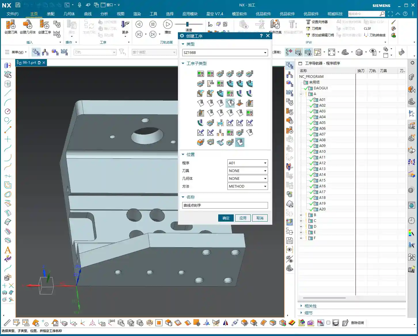
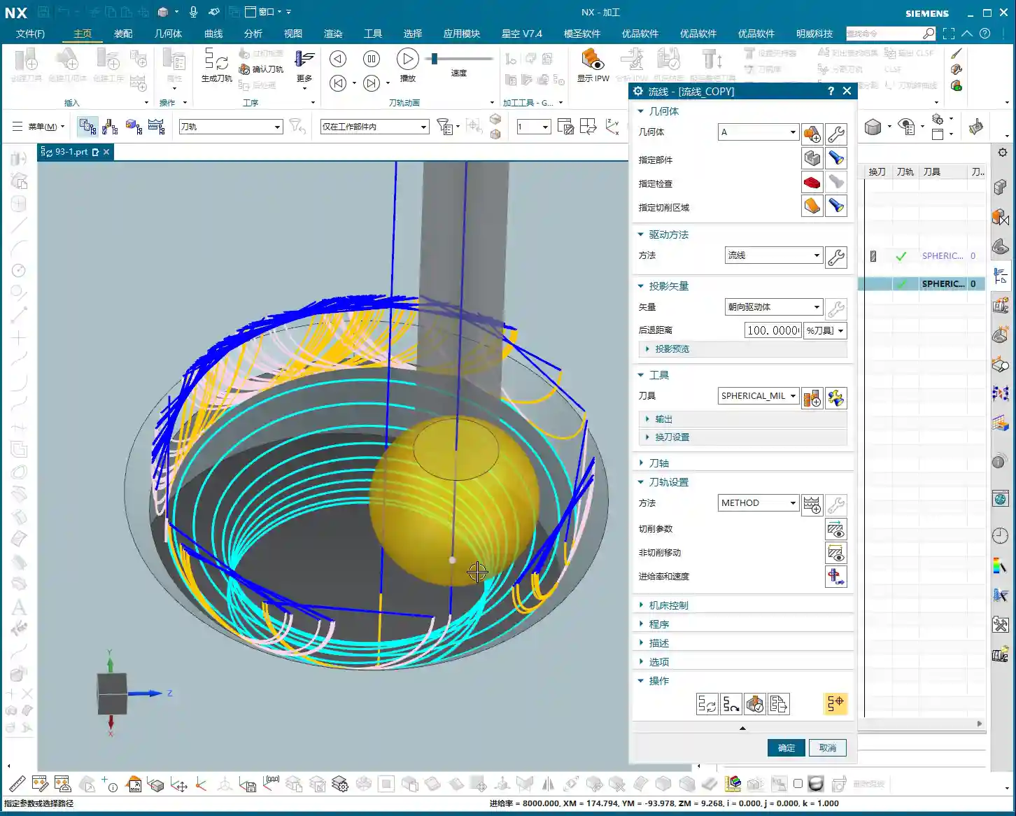
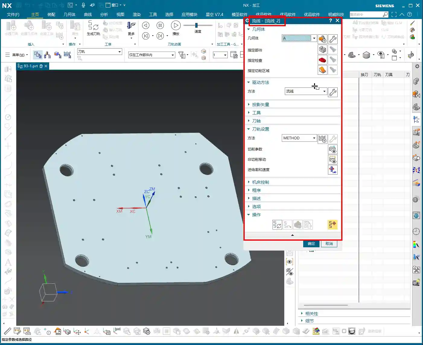
    Today, let’s talk about a particularly practical feature in Siemens NX CAM—Surface Drive Percentage. Textbooks might give you a few concepts, but in our actual work, this feature is crucial for refining toolpaths and boosting both efficiency and accuracy. Listen up, because these are “hardcore” insights I’ve gained from over a decade of hands-on experience at the machine!

    Core Concept: What Exactly is Surface Drive Percentage?

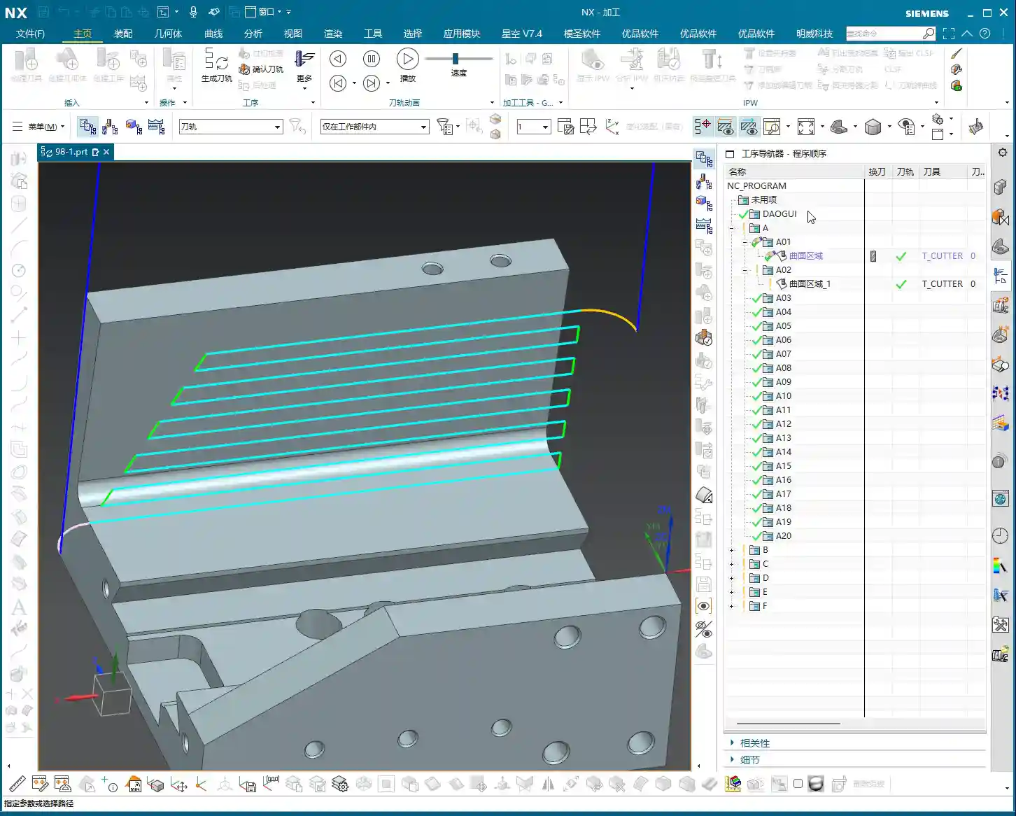
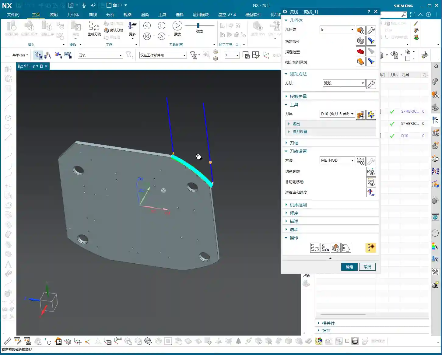
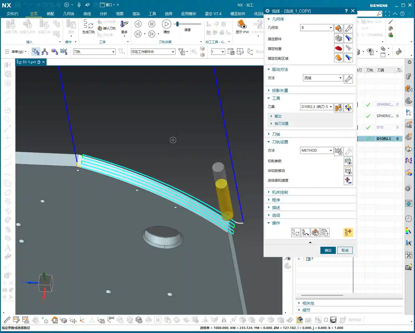
    Simply put, Surface Drive Percentage allows you to precisely control the start point, end point, and extension or trimming along the edges of your toolpath on the drive surface. Don’t underestimate these percentages; when used effectively, your toolpaths will run smoother, machining efficiency will be higher, and part accuracy will be better assured. It’s like drawing a “racetrack” for your tool, telling it where to start, where to stop, and even allowing it to run slightly off the track or finish early.

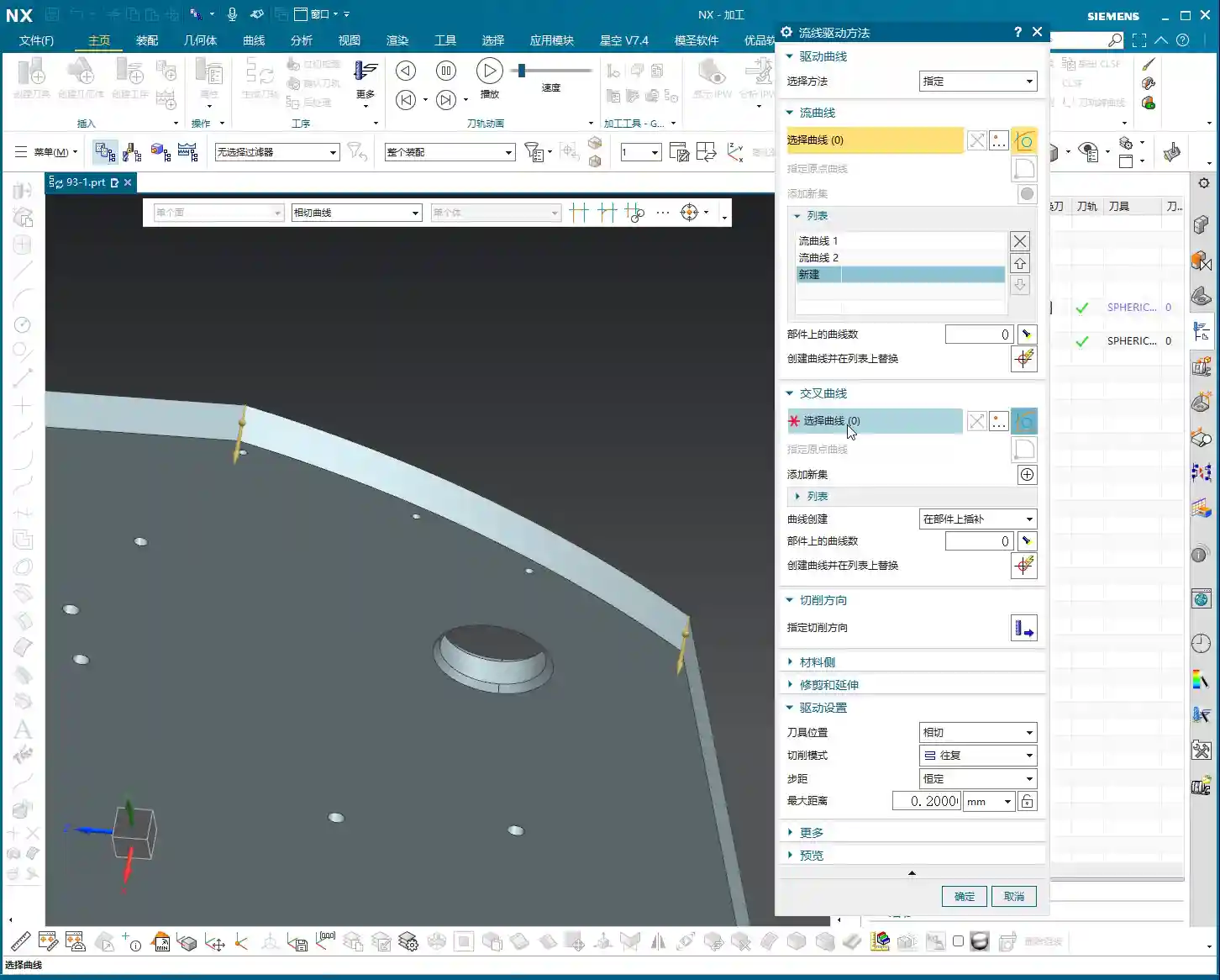
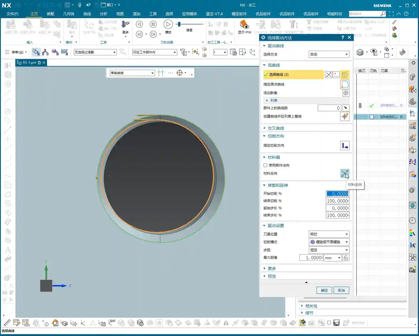
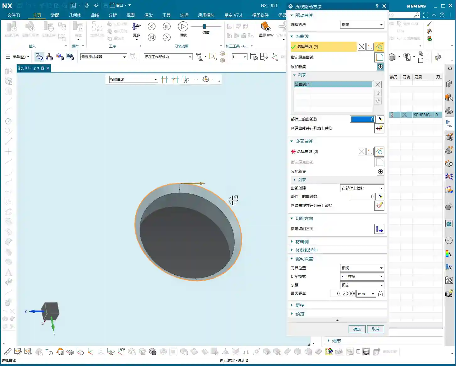
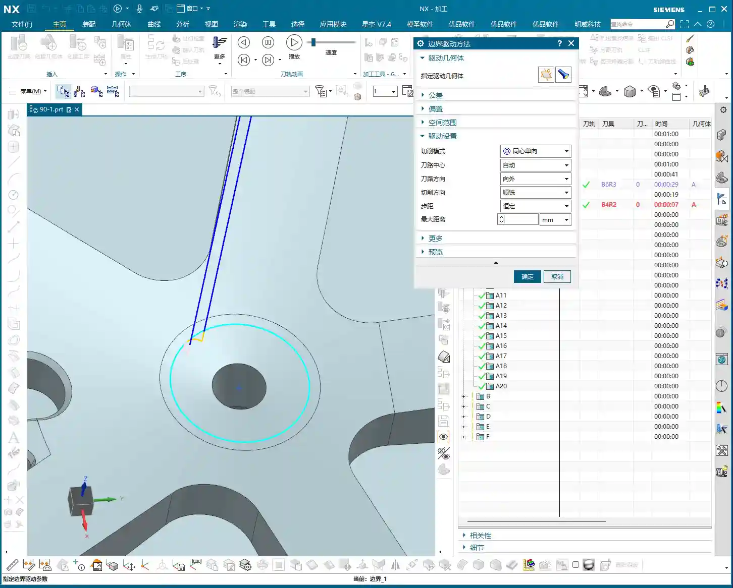
    Cutting Direction: The “Compass Needle” Determining the Start Point

    Before we dive into percentages, I must emphasize an absolutely critical prerequisite—the cutting direction. The cutting direction you choose directly determines where your “first start point” actually is!
    For instance, if you choose to cut from left to right, then the left side is the start point. If you reverse it to cut from right to left, then the right side immediately becomes the start point. Therefore, every time you adjust the percentages, always confirm that your cutting direction is as expected. Otherwise, you might spend ages adjusting percentages, only to find the results aren’t what you envisioned—because the start point itself has changed!

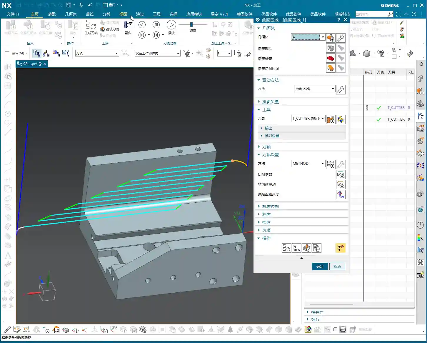
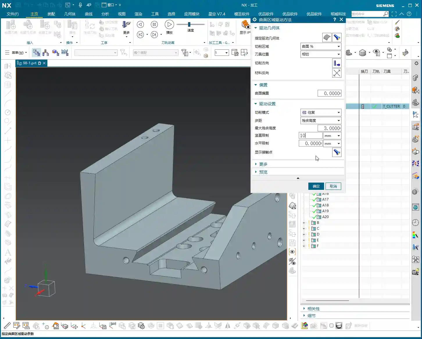
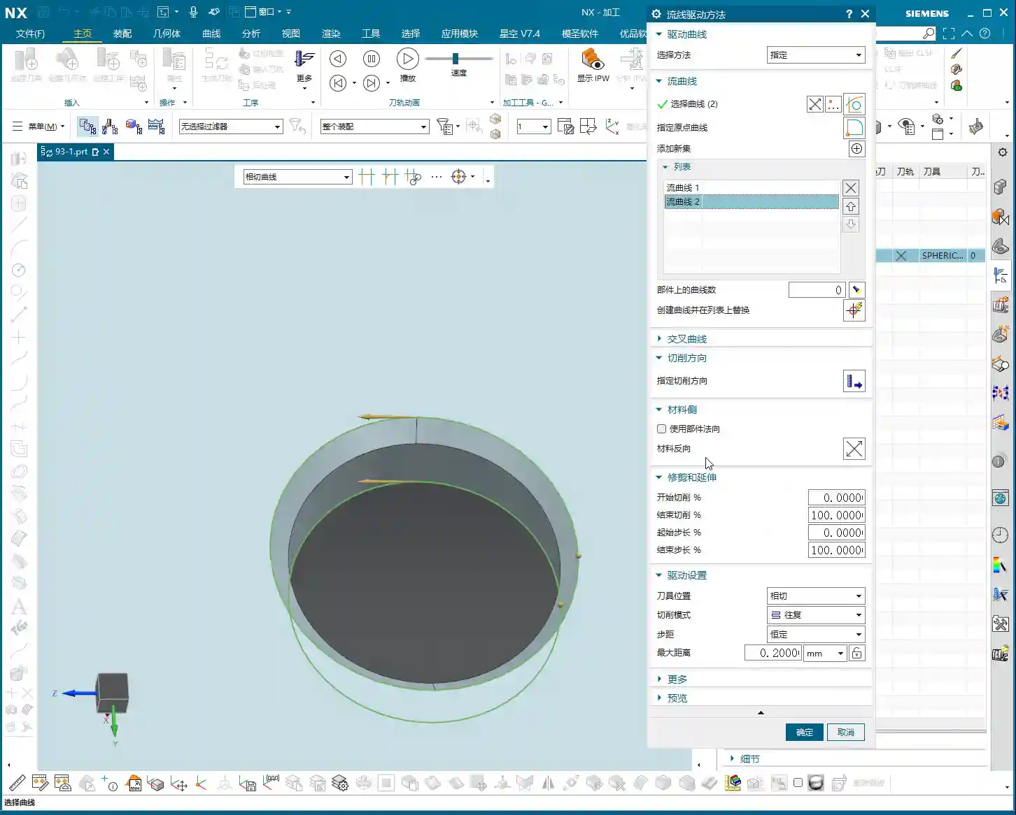
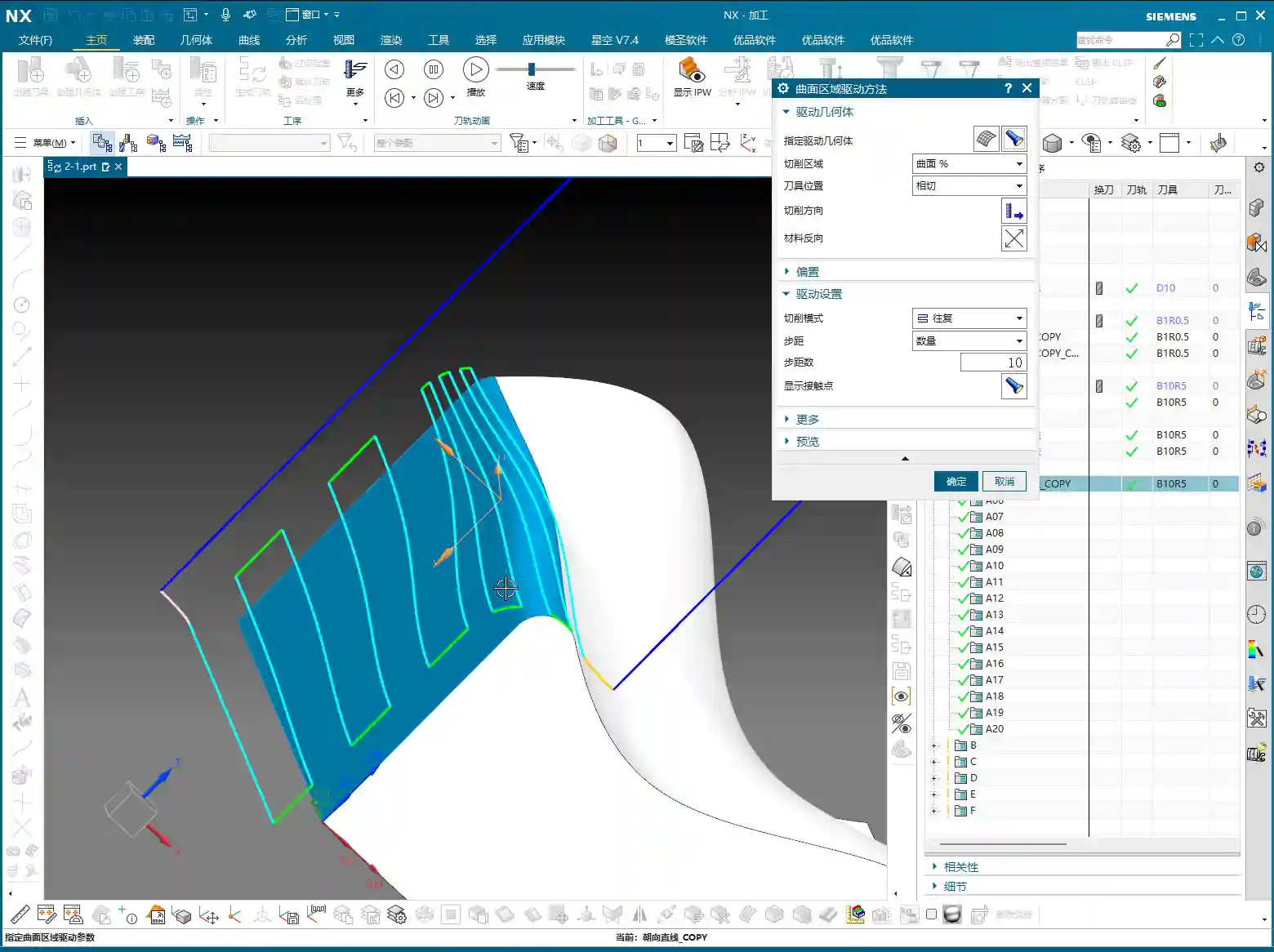
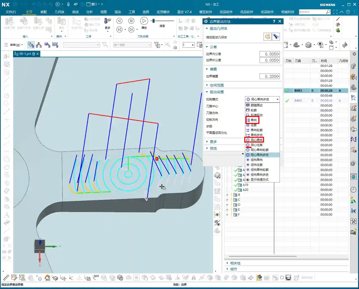
    Six Key Parameters: The “Scissors” for Toolpath Length and Boundaries

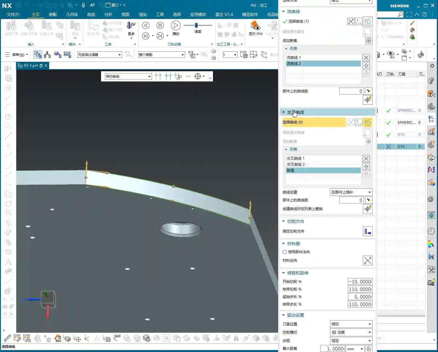
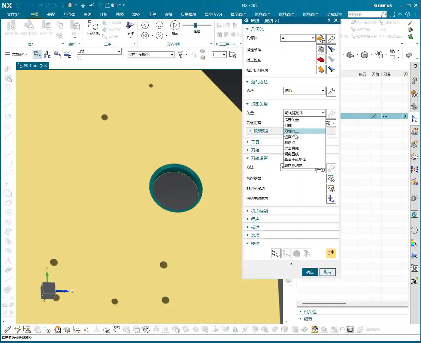
    Unlike “Streamline” operations, which typically only have four parameters, Surface Drive Percentage offers six parameters. These six parameters are divided into two categories: one controls the overall length of the toolpath, and the other controls the toolpath’s extension or trimming along the boundaries.

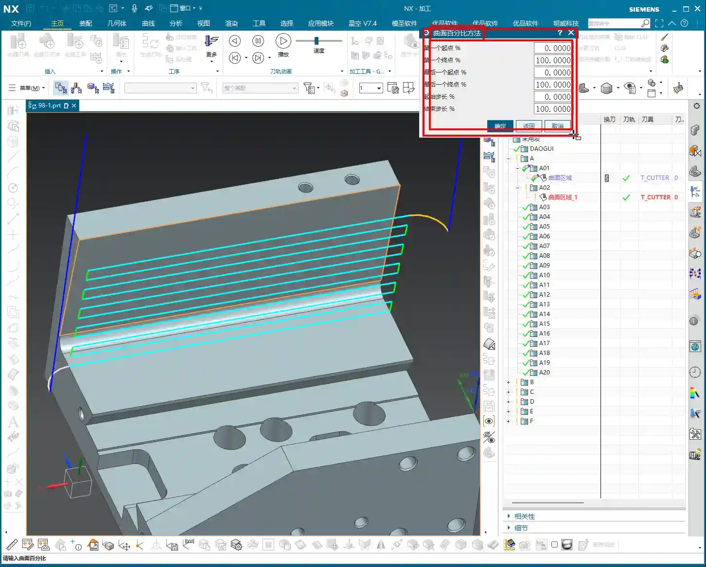
    1. Toolpath Length Control:

    * First Start Percentage
    * The default value is 0. Setting it to 0 means starting from the beginning of your chosen cutting direction.
    * If set to 20, the toolpath will start cutting 20% inward from the start point, leaving the first 20% untouched.
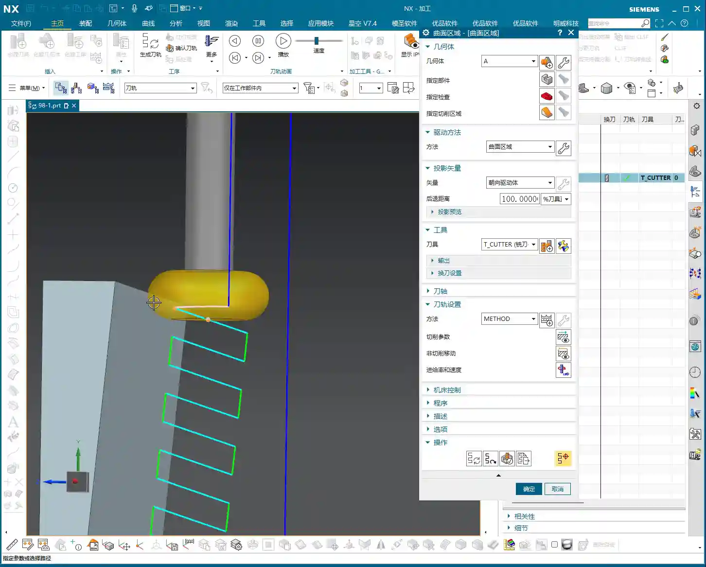
    * If set to -10 (a negative number), the toolpath will extend outward by 10% from the start point. This is extremely useful in specific situations, such as avoiding clamping elements or allowing the tool to enter the cut in a more stable condition.
    * First End Percentage
    * The default value is 100. Setting it to 100 means machining along the cutting direction all the way to the end of the drive surface.
    * If set to 50, the toolpath will only machine up to 50% of the total length and then stop.
    * If set to 120, the toolpath will extend outward by 20% from the end point. This is particularly effective when you want the tool to completely exit the part before retracting, preventing “witness marks” at the part’s edge.
    * Last Start Percentage
    * This refers to the opposite end of your drive surface. The logic is the same as “First Start Percentage,” but it applies to the opposing boundary.
    * Last End Percentage
    * Similarly applies to the opposite end of the drive surface, following the same logic as “First End Percentage.”

    **Master Wang’s Tip:** These four parameters control the overall length of the toolpath along the cutting direction. For example, if you have a long, narrow surface and only want to machine a central section, you can “trim” the toolpath by adjusting these four parameters.

    2. Boundary Trimming/Extension Control:

    * Start Compensation Percentage
    * The default value is 0. This “Start” refers to the first side boundary of the drive surface.
    * Set to 10, the toolpath will retract inward by 10% of the width from this boundary.
    * Set to -10, the toolpath will extend outward by 10% of the width from this boundary. This is primarily used to ensure the tool also cuts beyond the machining boundary on the side, guaranteeing a complete cut and avoiding “steps.”
    * End Compensation Percentage
    * The default value is 100. This “End” refers to the second side boundary of the drive surface.
    * Set to 99, the toolpath will leave 1% stock allowance at the end boundary. This is key!
    * Set to 110, the toolpath will extend outward by 10% of the width from this boundary.

    **Master Wang’s Tip:** These two parameters control the trimming and extension of the toolpath perpendicular to the cutting direction (or along the side boundaries). For example, if you want to leave some sidewall stock allowance on the surface edge, or allow the tool to completely overcut, you rely on these.

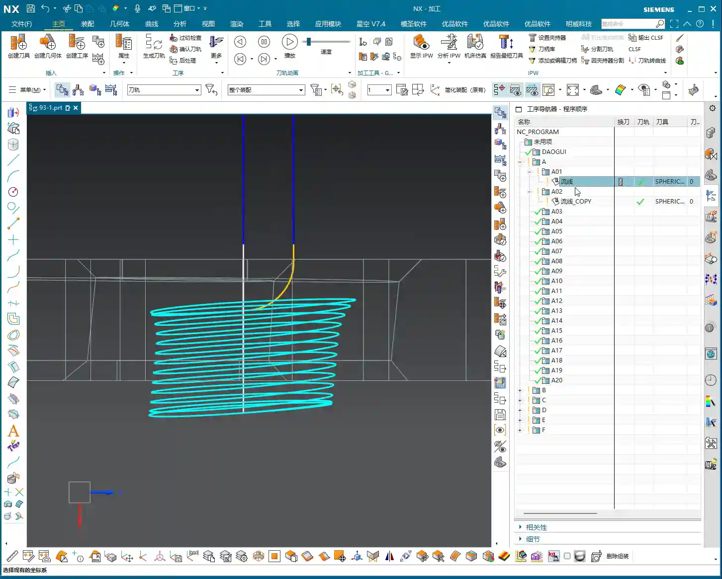
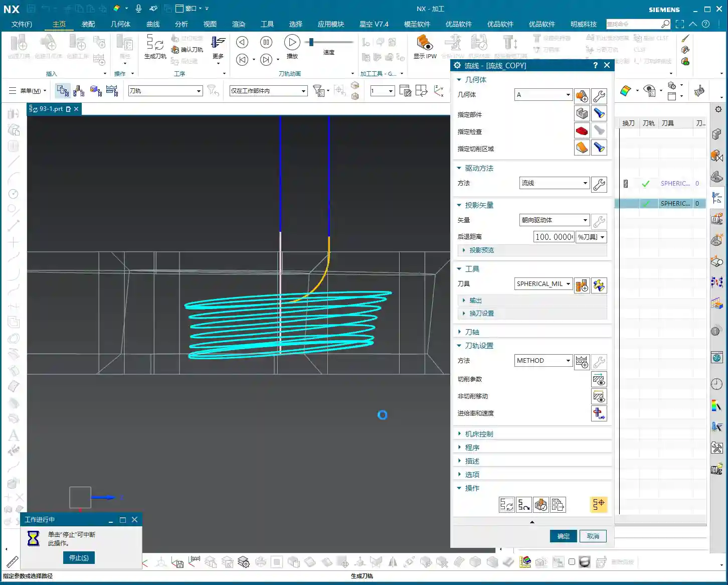
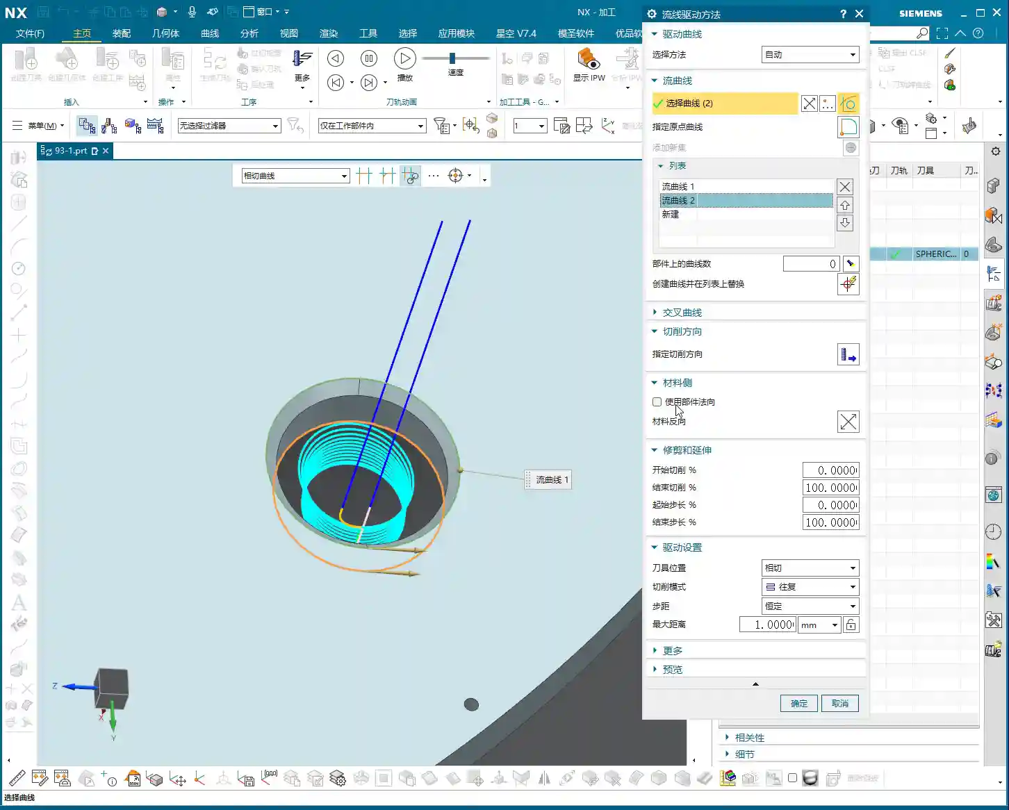
    Leveraging Percentages: Switching Between Roughing and Finishing

    Once you’re proficient with these percentages, you’ll find much greater flexibility in both roughing and finishing passes.

    * **During Roughing:**
    * To prevent overcutting, or to ensure sufficient stock allowance for the finishing pass, you can slightly adjust the “First Start Percentage” and “First End Percentage” to make the toolpath slightly shorter.
    * More importantly, for floor stock allowance, we typically set the “End Compensation Percentage” to 99 (meaning a 1% floor stock allowance is left) or 99.5. This leaves a thin layer of material on the floor for the finishing pass to remove. Sidewall stock allowance (e.g., 0.5mm) is set elsewhere; don’t confuse the two.

    * **During Finishing Pass:**
    * Typically, all percentages are set to their default values (0, 100, 0, 100, 0, 100) to ensure the tool covers the entire surface.
    * If edge blending or complete overcutting is needed, then “First End Percentage,” “Last End Percentage,” “Start Compensation Percentage,” and “End Compensation Percentage” can all be set appropriately to greater than 100 (e.g., 105 or 110), allowing the tool to completely cut beyond the part boundary.
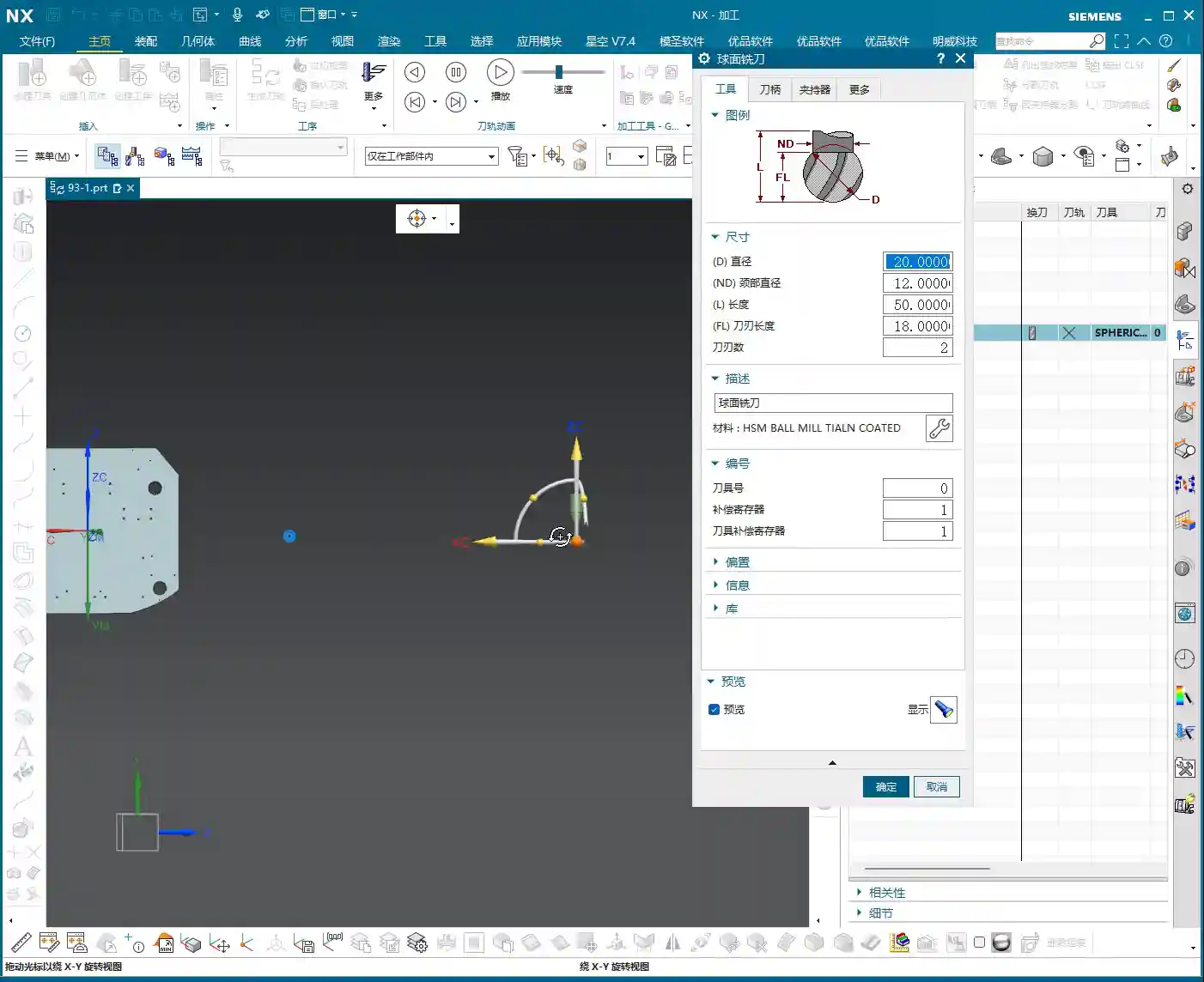
    * When machining difficult materials like titanium alloys or high-temperature nickel-based alloys, to reduce tool wear and improve surface quality, you can even extend slightly at the start point. This allows the tool to enter the cut in a more stable condition, avoiding impact.

    Summary: Pitfall Avoidance Guide

    1. Cutting Direction is King! Always confirm the cutting direction first. It determines where your “start point” is, and all percentages are calculated based on this direction. If you want the toolpath to start from a specific edge of the surface, make sure to adjust the cutting direction accordingly.
    2. Distinguish “Overall” from “Boundary”:
    * The first four (First Start/End, Last Start/End) control the overall length of the toolpath along the cutting direction.
    * The latter two (Start Compensation, End Compensation) control the extension or trimming of the toolpath along the drive surface boundaries, especially crucial for controlling floor stock allowance.
    3. Negative numbers extend, and values greater than 100 also extend: Don’t assume a negative number always means retracting; in “Start Percentage,” it means extending outward. Similarly, an End Percentage greater than 100 also means extending outward.
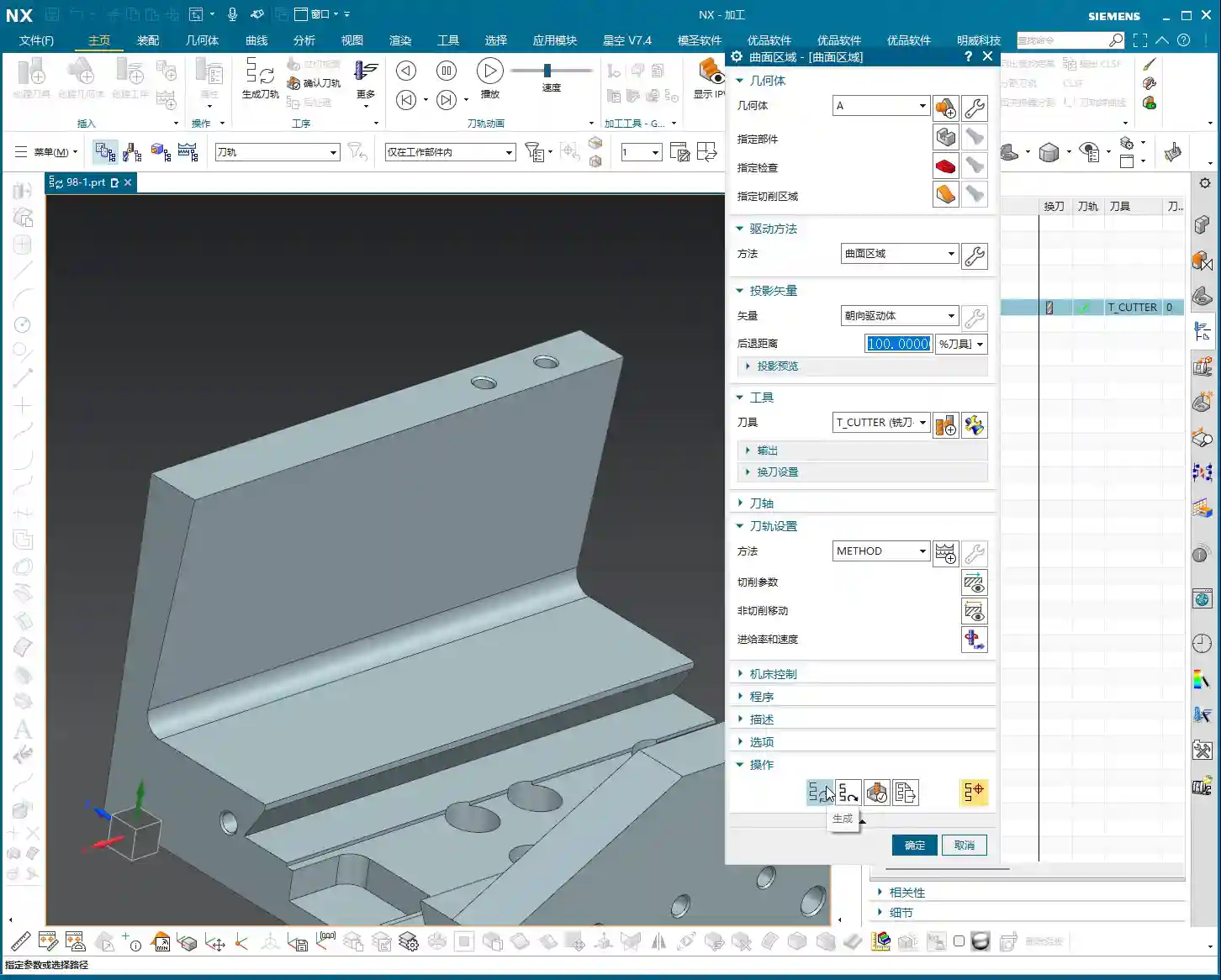
    4. Software simulation is good, but cutting sparks are better! Don’t just rely on the toolpath simulation in the software and assume everything is fine. In actual work, observe the cutting sparks, chip shape, and the actual dimensions after machining. No matter how realistic Siemens NX’s toolpath simulation is, it cannot replace your “sharp eye” and extensive practical experience.
    5. Don’t be afraid to experiment: When you’re first getting started with these settings, try different parameter combinations multiple times and observe their impact on the toolpath and machining results. Siemens NX provides powerful visualization features; test on a small scale first before applying to high-volume production.

    Mastering these techniques will give you finer control over surface toolpaths in Siemens NX CAM. Whether it’s boosting machining efficiency or ensuring part accuracy, you’ll be significantly more effective. This isn’t just a technical skill; it’s an art, relying on experience and adaptability!

    👤 About the Author:
    The author is a veteran CNC machining professional with 15 years of industry experience, specializing in UG NX programming. This article is an original work representing personal practical insights.

    ⚠️ Copyright Notice: Unauthorized reproduction or distribution without prior communication is strictly prohibited.

  • Siemens NX Surface Milling Pain Points: Master Wang’s Guide to Cut Direction, Scallop Height, and Tr

    📝 Key Takeaways:

    Siemens NX Surface Milling in Practice: In-depth Analysis of Drive Geometry, Cut Direction, and Scallop Height

    Drive Geometry: Defining the Machining Area is the First Step

    “Drive Geometry Not Specified”? Listen Up, This is Fundamental!

    Hello everyone, I’m Master Wang. Today, let’s continue discussing NX machining. Right off the bat, you might see the software prompt “Drive Geometry Not Specified.” It’s common, don’t panic.

    Simply put, this “drive geometry” tells the machine which surface or area you intend to machine. You can’t just let the tool run wild, can you? So, you absolutely must select it!

    Practical Case Study: Tool and Workpiece Interaction, Smart Selection is Key

    Take this example we have. If your tool radius matches the radius of the surface you’re machining, say both are R5 fillets, then you don’t need to select multiple surfaces. Just select this one surface as the drive geometry. It’s simple, direct, and maximizes efficiency.

    Cut Direction and Material Side Reversal: The “Soul” of the Tool Path

    Material Side Reversal: Mastering the Tool’s “Opening Move”

    Once the program is generated, you need to observe where the tool starts its cut. Sometimes, it might begin from an undesirable location. This is where “Material Side Reversal” comes in. This concept is similar to what we discussed in the last lesson regarding “Flowline.”

    Its purpose is to control which direction the tool starts machining the workpiece from. If the arrow points left, the tool starts from the left. If it points right, it starts from the right. Just click the small arrow to the desired direction for where you want the tool to engage. Don’t underestimate this; it directly impacts tool path planning and cutting stability.

    Cut Direction: The Key to Determining the Machining Path

    I must emphasize this “Cut Direction” again—it’s extremely important! It directly determines whether your tool moves up-and-down, left-and-right, or diagonally. Don’t just rely on the software simulation; observe its actual cutting path. See those little arrows? Click one, and the tool path instantly changes.

    • If you select the top arrow, the tool might move from top to bottom.
    • If you select the side arrow, the tool moves from this side to that side.
    • If you select the bottom arrow, it machines from bottom to top.

    Master Wang’s Tip: Different cut directions significantly impact surface finish and tool wear. On some complex surfaces, intelligently choosing the cut direction can noticeably reduce air cuts, improve machining efficiency, and even equalize cutting forces, extending tool life.

    Tool Position and Surface Offset: Finishing and Stock Allowance Control

    Tool Position: Tangent and Center

    Here are two options: “Tangent” and “Center.”

    • Tangent: The edge of the tool is tangent to your selected drive geometry. This is typically used for roughing or when a stock allowance is required.
    • Center: The centerline of the tool aligns with the drive geometry. This is generally used for finishing passes, or when you want the tool center to pass directly through a specific point or line.

    We’ve covered these two concepts in the “Flowline” lesson; they are fundamentals, so take some time to review them.

    Surface Offset: Leaving “Room” on the Sides

    What does “Surface Offset” mean? Simply put, it’s creating a gap between the tool and the surface you’re machining, essentially the same as “side stock allowance” or “radial stock.” If you input 1 mm, the tool will be 1 mm away from that surface. For roughing, you might leave a larger allowance, then set it to zero for finishing, or leave a finishing allowance.

    Practical Tip: Flexible use of surface offset can save you the trouble of repeatedly selecting different geometries. It allows direct control over machining allowance, enabling multi-stage machining with a single setup.

    Cutting Pattern: Choosing the Right Machining Rhythm

    Analyzing Various Modes: Spiral, One Way, Zigzag, Follow Periphery

    We’ve discussed cutting patterns many times before, so here’s a quick recap:

    • Zigzag: The tool moves back and forth, offering high efficiency but uneven cutting forces, which can affect surface quality.
    • One Way: The tool cuts in one direction, then retracts and returns for the next cut. This provides good surface quality but involves more retracts, leading to relatively lower efficiency.
    • Spiral: This pattern is typically suitable for enclosed areas with a center hole, as it allows for continuous, non-retracting tool paths. However, if your workpiece has open areas, a spiral tool path might not be ideal and is not recommended.
    • Follow Periphery: As the name suggests, the tool follows the peripheral contour of the workpiece. Since we’re dealing with an open area here, it’s not suitable.

    Pitfall Alert: When selecting a cutting pattern, always base it on the workpiece’s geometry and machining requirements. Using the wrong pattern can lead to low efficiency at best, and a scrapped workpiece at worst.

    Stepover and Scallop Height: The Core of Controlling Machining Accuracy and Efficiency

    The “Number” of Stepover Trap: Don’t Just Look at the Number, Calculate it Precisely

    When it comes to “stepover,” many people directly look at the “quantity” option and assume that entering a number means that many cuts. Listen closely, there’s a small trap here: when you enter a stepover quantity of 10, it actually performs 11 cuts! That’s because the first cut isn’t counted; it’s “1 plus 10”!

    If you input 20 cuts, it becomes denser; 50 cuts, even denser. But the problem is, if you only input the quantity, you don’t know the actual depth of cut for each pass, do you? You’d have to calculate the total height divided by the number of cuts yourself. How cumbersome is that? And inaccurate calculations will affect the machining result.

    Master Wang’s Insight: Relying on guesswork for stepover quantity will never achieve optimal surface quality and efficiency. That’s why we need to introduce the concept of “scallop height.”

    Scallop Height: The Core Parameter for Intuitive Control of Surface Quality

    Previously, we often overlooked the “Maximum Scallop Height” parameter. Today, let’s discuss it thoroughly. This “Maximum Scallop Height” is truly the key to controlling the “stepover” between each cut! It directly determines the height of the tool marks left on the machined surface, also known as the size of the “fish scale pattern” or cusps.

    Think about it: if you’re aiming for a high surface finish, this scallop height needs to be set smaller, for example, 0.01 mm. This results in a very dense tool path, and the surface will be smoother. If it’s roughing, you can set it larger to increase speed.

    Precision Control: By mastering the maximum scallop height, you can truly achieve precise control over the workpiece’s surface quality, rather than relying on luck or “good enough.”

    Vertical and Horizontal Limits: Defining Each Depth of Cut, Eliminating Ambiguity

    Distinguishing “Vertical” from “Horizontal”: Machining Direction is Key

    Now, let’s look at “Vertical Limit” and “Horizontal Limit.” Many newcomers get these confused. It’s actually quite simple:

    • Vertical: This refers to directions like top-to-bottom or bottom-to-top. For instance, machining a vertical sidewall is a vertical cut.
    • Horizontal: This means flat, parallel to the ground. For example, machining a planar surface.

    The kind of tool path we’re currently discussing, moving from top to bottom, is a vertical cut. Since it’s vertical, your “Vertical Limit” setting will be effective! For example, if I set the vertical limit to 4 mm, then you’ll see that each cut precisely steps down 4 mm, clear as day.

    Conversely, if your machining direction is horizontal, changing the “Vertical Limit” will be completely useless! It’s not cutting in the vertical direction, so changing it is pointless. You absolutely must distinguish this!

    Master Wang’s “Universal” Fail-Safe Method: If You Can’t Tell, Do This!

    I know that sometimes the workpiece geometry is too complex, or you lack experience, and you just can’t figure out if it’s vertical or horizontal. No worries, Master Wang will teach you a “universal” troubleshooting method:

    If you truly can’t distinguish, just set both the “Vertical Limit” and “Horizontal Limit” to a very small value, such as 0.2 mm (approx. 0.008 inch). This way, whether it’s a vertical or horizontal cut, each depth of cut (or lateral stepover) will be restricted to within 0.2 mm, ensuring machining accuracy and surface quality. A program generated this way will definitely be problem-free, definitely correct! Even if you don’t fully understand it, you’ll still reliably get the job done.

    Summary: Pitfall Avoidance Guide

    Alright, we’ve covered quite a few hard-hitting topics today. Let me summarize some key points for avoiding pitfalls:

    1. Drive Geometry: Must be selected! Only by choosing the correct area will you machine the right place.
    2. Material Side Reversal and Cut Direction: These are the “batons” for your tool path. To control where the tool starts and where it moves, click the correct arrows; don’t let the tool wander aimlessly.
    3. Surface Offset: This is your side stock allowance; set it flexibly for roughing and finishing stages.
    4. Cutting Pattern: Choose based on the workpiece’s open/closed nature and surface requirements. Don’t carelessly use “Spiral” in open areas.
    5. Stepover and Scallop Height: These are core to controlling accuracy and efficiency. Don’t just look at the stepover quantity; focus on “Maximum Scallop Height” as it directly determines your surface quality.
    6. Vertical and Horizontal Limits: Understand whether you’re machining a “vertical” or “horizontal” surface. If you can’t tell, Master Wang’s universal method is to set both to a small value (e.g., 0.2 mm / approx. 0.008 inch), guaranteeing your output will be problem-free!

    These are practical tips that textbooks might not fully explain. Go back and practice more. Once you’ve mastered these parameters, your Siemens NX Surface Milling skills will truly advance to the next level.

    Next lesson, we’ll discuss “Surface Percentage,” an advanced feature. That’s all for today, see you next time!

    👤 About the Author:
    The author is a veteran CNC machining professional with 15 years of industry experience, specializing in UG NX programming. This article is an original work representing personal practical insights.

    ⚠️ Copyright Notice: Unauthorized reproduction or distribution without prior communication is strictly prohibited.

  • Practical Siemens NX Programming: Master Wang’s Step-by-Step Guide to Surface Driven Machining, Spec

    📝 Key Takeaways: Master Wang introduces the Siemens NX Surface Driven operation, a powerful tool for complex surfaces and undercut machining. This is a summary of an experienced engineer’s expertise. Key topics cover command application scenarios, model preprocessing, tool selection, and parameter settings, with a special emphasis on cleaning up details like small holes and chamfers in the model. This troubleshooting guide helps you avoid common beginner mistakes, improving programming and machining efficiency from a practical perspective.

    The Expert’s Take: The Standing of Surface Driven Machining in the Industry

    Hello everyone, I’m Old Wang. Today, let’s talk about the “Surface Driven” operation in Siemens NX. Listen up, this operation is genuinely used quite often in our actual machining work. Especially for complex parts and jobs involving undercuts, it’s like your right-hand man.

    Why Is It So Important?

    You might think it’s not used much in daily work, right? That’s because you haven’t encountered any tough challenges yet! For us seasoned engineers, mastering this command can solve major problems. Unlike some other commands you might not touch for months or even a year, when you do use this one, it’s always at a critical moment. However, it’s true that this operation isn’t very beginner-friendly. When you first started programming, you probably felt confused, couldn’t figure it out, and weren’t familiar with it – that’s all normal.

    What Exactly Is It?

    Simply put, Surface Driven is a powerful tool in Siemens NX for machining complex surfaces or features with “undercuts”. It’s somewhat similar to “Curve Driven” and “Boundary Driven,” but the key difference is that Surface Driven directly selects a face to drive the toolpath. Furthermore, it can better handle special structures with R-angles on side walls and bottoms, especially facilitating undercut machining.

    Process Essentials: Practical Application Scenarios

    Specializing in Undercuts and Angled Surfaces

    Remember this: When do we typically use the Surface Driven command? Mainly for machining undercuts! With standard 3-axis machining, vertical and small angled surfaces might be manageable. However, when you encounter large angled surfaces or features with undercuts at the bottom, the tool is prone to tool deflection or interference. This is when you need to use Surface Driven. It allows you to use the side of the tool for machining, perfectly avoiding interference.

    Model Preprocessing: Proper Preparation Is Key

    Before you start machining, the model must be cleaned up first! I’ve said it countless times: Seal or delete all those small holes, chamfers, broken faces, and through holes on the surfaces you intend to machine! Don’t be lazy! These tiny, fragmented features will cause issues for your toolpath generation, potentially leading to unnecessary pauses or even errors. Just like I demonstrated earlier, if the model precision isn’t good, even deleting those small chamfers can be a hassle. It’s best to handle this during the CAD phase, or copy the part to another layer, keeping only the faces to be machined and ensuring they are clean. Otherwise, you might see no issues in the software simulation, but once it’s on the machine, the toolpath will be erratic, the cutting sparks will look wrong, and efficiency will be impossible!

    Tooling and Parameters: A Seasoned Engineer’s Choice

    T-Slot Cutter / Dovetail Cutter: The Ultimate Tool for Undercut Machining

    For undercut machining, tool selection is paramount. Typically, we use a T-slot cutter (or similar dovetail cutter). The characteristic of such tools is a large head diameter with a slender neck, making it easy to reach into undercut areas. Parameter settings must be precise:

    • Tool Diameter (D): For example, 25mm. This is the diameter of the tool’s largest cutting portion.
    • Neck Diameter (d): For example, 10mm. The neck must be thinner than the head to fit into the undercut.
    • Bottom Radius (R): For example, 5mm. This is the radius of the tool’s bottom corner, directly affecting the resulting fillet radius after machining.
    • Bottom Length: This is also very important. For instance, here it is 10mm (composed of two 5mm radii). This length must ensure that the tool’s effective cutting portion can cover the machining area, while simultaneously preventing interference between the tool neck or shank and the workpiece.

    Remember, don’t just rely on software parameters. Always measure the actual tool before mounting it on the machine, especially the effective flute length and corner radius. Even a slight discrepancy could lead to tool deflection or improper machining, potentially scrapping the part!

    Coordinate System and Cutting Method

    I won’t elaborate on the coordinate system; it’s business as usual. Just create one anywhere near the machining area, as long as it’s valid and provides proper positioning. As for the cutting method, we generally default to selecting “Towards Cut Stock.” This is Siemens NX’s default option, the most commonly used, and suitable for most situations. If your part is exceptionally complex, you might need to consider other cutting methods, but we can discuss those later.

    Summary: Pitfall Avoidance Guide

    Listen closely; these are hardcore pitfall avoidance tips compiled from my 15 years of experience as Master Wang:

    • Model First, Clean Surfaces Are King: For any complex surface machining, model cleanliness is paramount! Small features and discontinuous faces are “cancerous” for toolpath generation; they will make your toolpaths uneven, and can even lead to chip re-cutting or tool alarms. Spending time cleaning the model upfront will save you several times that in debugging later.
    • Tool Matching, No Brute Force: Not just any tool can machine an undercut. T-slot cutters and dovetail cutters are your first choice. Parameters must be precisely calculated, with key focus on neck clearance and effective cutting length. Choosing the wrong tool is like running headfirst into a wall.
    • Be Observant, Pay Attention to All Cues: Don’t just stare at the computer simulation; that’s only theoretical. During actual cutting, observe the sparks, listen to the sound, and feel the vibration. Incorrect spark color, harsh sounds, or abnormal vibration are all the machine “talking” to you. Stop the machine immediately to inspect and prevent major accidents.
    • Precision Calibration, Adapt and Overcome: Machine accuracy will never be perfect. When encountering precision issues of ±0.005mm, don’t just complain. Try to compensate through process compensation, adjusting toolpath strategies, or even localized manual finishing. High precision is achieved through meticulous effort and fine-tuning.
    • Cost Efficiency, Ingrained in Your Core: All toolpath optimizations ultimately aim to improve efficiency and reduce costs. Every rapid move is burning money; every defective part is wasting time. When designing toolpaths, always think about how to reduce non-cutting moves, optimize feed rates, and extend tool life. This is not just about technique; it’s the crystallization of experience and wisdom.

    👤 About the Author:
    The author is a veteran CNC machining professional with 15 years of industry experience, specializing in UG NX programming. This article is an original work representing personal practical insights.

    ⚠️ Copyright Notice: Unauthorized reproduction or distribution without prior communication is strictly prohibited.

  • NX Streamline Milling: Master Wang Explains Cross Curves and Extension/Trimming, Conquering Undercut

    📝 Key Takeaways: Master Wang uses real-world examples to provide a hands-on explanation of the core techniques for cross curves and extension/trimming in NX Streamline Milling. He meticulously compares the differences in tool selection between Streamline and Guide Curve operations and highlights how to leverage Streamline’s unique advantages to efficiently machine complex undercut surfaces. This tutorial emphasizes practicality, efficiency, and cost-effectiveness, offering a series of troubleshooting tips to help you avoid errors and master practical essentials not found in textbooks.

    Master Wang’s Talk: Streamline and Cross Curves – All the Ins and Outs Are Here

    Hello everyone, I’m Master Wang. Today, let’s talk about “Streamline Milling” in NX, especially its interaction with “Cross Curves.” There’s a lot to know here. While the user interface might seem similar to Guide Curve machining, fundamentally, they’re quite different. Listen up, these are practical tips you won’t find in textbooks. They’ll save you a lot of trial and error on the shop floor and genuinely boost your efficiency!

    Step One: Workpiece Coordinate System Setup and Geometry Preparation

    To get the job done, you first need to get your setup right. Let’s take the workpiece we have; this area needs to be machined using Streamline. So, the first critical step is to correctly position your Work Coordinate System (WCS).
    Remember, the Z-axis must point upwards – that’s a golden rule for milling operations! If your coordinate system is incorrect, your tool paths will be useless.
    Next, you need to create the geometry for machining. Some younger engineers prefer to use the built-in NX features, which is fine. But if you have your own templates, calling them directly is much faster and more reliable, saving you from reconfiguring everything each time.

    Step Two: Operation Selection and Curve Definition – Distinguishing “Streamline” from “Cross” is Key!

    Alright, with the coordinate system and geometry in place, the next step is to select the appropriate operation. We’ll insert a machining operation, select a Type B operation (this usually refers to a specific cutting strategy or tool type), and then choose the “Streamline” machining method.

    Next, we define the critical curves. Here, I want to emphasize that this is where beginners most often get confused, and it’s also where you’re most likely to encounter unexpected Depth of Cut (DOC)!

    First, you define the “Streamline Curves.” Typically, we select two, such as “Streamline 1” and “Streamline 2.” These define the primary direction and extent of the tool path.

    Next comes the main event: the “Cross Curves.” You’ll often find one or more auxiliary curves between the two Streamline Curves. These are the Cross Curves. Master Wang tells you, in Streamline Milling, these Cross Curves must be selected, and selected correctly! They determine the distribution and Stepover of the tool along the Streamline direction.

    Listen up, distinguishing between “Streamline Curves” and “Cross Curves” is fundamental! The Streamline Curves are the main framework of your tool path, defining the tool’s direction; the Cross Curves are auxiliary lines, determining the density and distribution of the tool along that framework. Do not select them incorrectly, or your tool path will either error out or be completely unusable! The direction arrows are secondary; up, down, left, or right are all acceptable, the key is to select the correct curves themselves.

    Unique Advantages of NX Streamline Milling: Tool Selection and Parameter Fine-Tuning

    Breaking Through Guide Curve Tool Limitations, Boosting Machining Efficiency

    Many younger engineers new to NX programming might think Streamline Milling is similar to Guide Curve Milling. Indeed, from an operational standpoint, both involve selecting a few curves and generating tool paths. However, Streamline Milling has an advantage that Guide Curve operations can’t match: tool selection flexibility!

    In newer versions of NX, Streamline Milling allows you to freely select various tool types, such as corner radius end mills (R-cutters), flat end mills, and even some custom tools. Guide Curve operations, however, are often limited to ball end mills. What does this mean?

    This means when you need to machine parts with small fillets, undercuts, or complex curved surfaces, Streamline Milling enables you to select a more suitable tool, significantly improving both machining efficiency and surface finish. For instance, for the same undercut feature, machining with a corner radius end mill will definitely be faster than with a ball end mill, and the Depth of Cut will be more stable. This is a tangible cost benefit, directly reflected in machining time!

    Parameter Deep Dive: The Art of Extension and Trimming

    Another powerful aspect of Streamline Milling is its precise control over “extension” and “trimming” parameters. This function helps you prevent incomplete cutting or over-cutting issues when machining complex areas.

    In the “Trim/Extend” options, you’ll see “Start Length” and “End Length.” These two parameters aren’t to be filled in randomly; they correspond to the start and end points of your selected Streamline Curves. If you select Streamline 1 first, then Streamline 2, “Start Length” will control the extension or trimming at the Streamline 1 end, while “End Length” will control the Streamline 2 end.

    Here’s a tip: Enter a positive value for the extension length, and the tool path will extend outwards; enter a negative value, and it will shorten inwards. This function is particularly useful when dealing with irregular boundaries or when needing to avoid tool collisions. Don’t just rely on software simulation; the actual cutting sparks on the machine are the ultimate test of your parameters!

    Furthermore, “Vertical Extension” and “Horizontal Extension” control the tool path’s expansion in different directions. When dealing with features like undercuts, we often need to adjust the “Horizontal Extension” to ensure the tool fully covers the machining area or avoids cutting where it shouldn’t.

    Machining Strategy: Avoiding the “Closed Region” Pitfall

    Many younger engineers ask why the “Start Length” and “End Length” parameters in Streamline Milling are sometimes grayed out and cannot be adjusted.

    This is because your selected streamline forms a closed region, such as a complete circle or a closed annular groove. In such cases, there are no clear “start” and “end” points, so these parameters become inactive. You can only adjust extension or trimming when your selected streamline is an open curve.

    Therefore, before performing Streamline Milling, carefully observe your geometric features to determine if they are suitable for using these extension parameters. For closed circular undercuts, even though extension isn’t possible, the streamline operation itself can effectively complete the machining with high efficiency.

    Streamline Milling Applications and Efficiency Improvement

    Efficiently Conquering “Undercuts” and Complex Surface Milling

    In my many years in machining, while Streamline Milling isn’t as common in production as Area Milling, it’s an absolute ‘ace’ when tackling specific complex features!

    The most typical application scenarios are machining “undercuts” and complex curved grooves. These features are often difficult to complete in a single operation using conventional Area Milling or Contour Milling, or they require extensive programming time, and the tool path efficiency is low.

    However, with Streamline Milling, especially when combined with flexible tool selection like a corner radius end mill (R-cutter), it can be easily achieved. You just need to define the streamline and cross curves, and NX will automatically generate efficient and smooth tool paths. For complex arc undercuts like these, I recommend don’t even consider other commands; just use Streamline, and you’ll achieve twice the result with half the effort!

    The Golden Rule of Operation Selection: Best Fit is Best

    Those of us in machining need to remember one thing: there is no single best command, only the most suitable one.

    Streamline Milling has its unique advantages, especially in tool selection and handling undercuts, which many other commands cannot replace. However, it also has limitations; for instance, for most flat or open area milling, Area Milling will be more efficient. Therefore, when encountering different parts and different machining regions, we must flexibly select the operation.

    These two points are critical for improving efficiency and reducing costs: first, understanding the characteristics of each command; and second, selecting the most appropriate machining operation and tool based on part features and machining requirements.

    Summary: Pitfall Avoidance Guide

    1. Distinguish Streamline from Cross Curves: This is the foundation of Streamline Milling. Streamlines define the primary direction, while Cross Curves determine the Stepover. Select them incorrectly, and your tool path is wasted.
    2. Flexible Tool Selection: A major advantage of Streamline Milling is the ability to use non-ball end mills, such as corner radius end mills (R-cutters). Fully leveraging this can significantly boost efficiency and surface finish. Stop rigidly sticking to ball end mills!
    3. Understand Extension Parameter Limitations: “Start/End Length” parameters are only effective for open curves. If you encounter a closed region, these parameters will be grayed out; don’t overthink it, proceed with normal calculation.
    4. Validate Parameters in Practice: After setting extension and trimming parameters, don’t just rely on NX simulation. Adjust them based on actual cutting conditions. Cutting sparks and chip formation are all indicators for judging the rationality of your parameters.
    5. Practice Diligently and Experiment: NX parameters are highly varied. Only by exploring and practicing extensively on your own can you truly grasp its essence.
    6. No Universal Operation: While Streamline Milling is powerful, it’s not suitable for all situations. In practical work, you must select the most appropriate operation based on the machining features to achieve optimal results.

    Alright, that wraps up our discussion on Streamline Milling for today. I hope these experiences of mine can help you avoid pitfalls and increase your output in actual machining. See you next time!

    👤 About the Author:
    The author is a veteran CNC machining professional with 15 years of industry experience, specializing in UG NX programming. This article is an original work representing personal practical insights.

    ⚠️ Copyright Notice: Unauthorized reproduction or distribution without prior communication is strictly prohibited.

  • Siemens NX Streamline Toolpath Master Class: Master Wang on Trimming, Extension, and Cutting Directi

    📝 Key Takeaways:

    Practical Siemens NX Streamline Toolpaths: The Secrets of Cutting and Extension

    Hello everyone, I’m Master Wang. Today, let’s continue di…

    Hello everyone, I’m Master Wang. Today, let’s continue discussing the core technologies in Siemens NX, especially some critical settings for Streamline toolpaths. Listen closely: if you don’t grasp these points, simply failing to generate a program is minor. On the machine, you could face significant issues!

    I. Cutting Direction: The Soul of the Toolpath

    As we’ve mentioned before, the Cutting Direction parameter is critically important! It determines how the tool engages with the workpiece, directly impacting cutting forces, surface quality, and tool life. In Siemens NX, when you double-click to open a program and enter the method editing interface, this is the first thing you must pay attention to.

    1. Material Side vs. Tool Side: Mastering Internal and External

    What is the “Material Side”? Simply put, it determines which **Tool Side** you intend to machine. In Siemens NX, there’s a small arrow; clicking “Reverse Material” will toggle it. If the arrow points outwards, your tool will machine the outer side of the part. Conversely, if the arrow points inwards, the tool machines the inner side, which is what we commonly refer to as “machining an internal cavity.”

    Master Wang’s Tip: Don’t underestimate this arrow; it’s your tool’s eye! For external features, the arrow points outwards; for internal cavities, it points inwards. Especially when performing Streamline machining in **enclosed regions**, always confirm the arrow’s direction. If the direction is incorrect, your entire toolpath will be unusable and simply won’t generate.

    2. The Culprit Behind Toolpath Calculation Errors

    Many new users encounter issues where the program fails to generate or produces “empty toolpaths” or “air cuts,” often due to an incorrect **Cutting Direction setting**. If the tool is supposed to machine inside the part but you’ve directed it outwards, the system will naturally give you a “blank canvas”—because there’s simply no material to cut! So, when a toolpath fails to generate, your first reaction should be to check this arrow. See if “Reverse Material” needs to be clicked; often, the program will then appear.

    II. Streamline Toolpath Trimming and Extension: Precision Refinement

    One of the most flexible aspects of Streamline toolpaths is their **Start Extension** and **End Extension** capabilities. These settings allow you to precisely define where your toolpath begins and ends, avoiding entry/exit marks in critical areas and improving surface quality.

    1. The Mystery of 0-100%: Baseline Length

    In Siemens NX, the length of each drive curve used to generate a Streamline toolpath is defaulted by the system to **100%**. Once you understand this baseline, you can master trimming and extension.

    • Start Extension:

      • Entering a **positive value (e.g., 10)**: Trims 10% of the length “inward” from the drive curve’s start point. The tool will engage later, avoiding marks at the start position.
      • Entering a **negative value (e.g., -10)**: Extends 10% of the length “outward” from the drive curve’s start point. The tool will engage earlier, entering the cut outside the part to ensure stable cutting and prevent gouging.

    • End Extension:

      • Entering a **value less than 100% (e.g., 50)**: Trims 50% of the length “inward” from the drive curve’s end point. The tool will retract earlier, preventing overcutting or marring at the end position.
      • Entering a **value greater than 100% (e.g., 150)**: Extends 50% of the length “outward” from the drive curve’s end point (total length reaching 150%). The tool will retract later, exiting the cut outside the part to also ensure stable cutting.

    Master Wang’s Tip: Remember this logic: for the start point, a negative value extends, a positive value trims; for the end point, a value greater than 100% extends, and a value less than 100% trims. This is crucial when machining mold surfaces, especially at the transition between steep and shallow areas, or during finishing passes, as it effectively controls the tool’s entry and exit points, preventing witness marks and blend lines.

    III. Cutting Strategy: Tangent or Trace?

    In Streamline toolpaths, there are two important cutting strategies: **Tangent** and **Trace**. Their difference lies in the relationship between the tool and your selected surface.

    1. Tangent: The General Choice

    In “Tangent” mode, the tool’s **centerline** will follow your selected drive curve or surface edge. This typically means the tool’s radius will extend beyond the selected face. However, if “Part Protection” is enabled, the tool will not overcut. This is our most commonly used and safest strategy, suitable for most situations.

    2. Trace: Precise Control

    “Trace” mode is more intricate; it forces the tool’s **Tool Contact Point** (e.g., the center of a ball nose, or the intersection of a flat end mill’s edge with the face) to follow your selected drive curve or surface. In this scenario, if you directly select the original face, the tool’s centerline will run outside the face, causing overcutting!

    Master Wang’s Tip: To effectively use “Trace,” you need to learn to “cheat”! The best method is to first create a **Tool Radius Offset Body**. For example, offset the surface you want to machine outwards by the tool’s radius to create a new auxiliary surface. Then, in “Trace” mode, select this offset body. This way, while the tool’s contact point is on the offset body, its centerline will align perfectly with your actual machining surface, achieving precise cutting without overcutting. This technique is particularly effective when machining **special structures or thin-walled parts**, as it significantly reduces unnecessary retracts and improves machining stability.

    Additionally, when you find unnecessary **Retracts** in the toolpath, besides checking the “Through Material” settings, you can sometimes consider creating a **Dummy Body** to block it off. This keeps the tool machining within the specified region, avoiding unnecessary lifts and air moves.

    IV. Tolerance and Other Settings: Details Determine Success

    As for **Tolerance**, I’ve covered it many times in previous tutorials. Generally, Siemens NX’s default tolerance is sufficient. When we create templates, we typically adjust these common parameters to their optimal settings. Unless there are specific precision requirements, do not easily alter it, as this directly affects toolpath calculation time and final surface accuracy.

    Cutting patterns such as Helical, Zig, One-Way, and Zig-Zag are fundamental, and I won’t elaborate on them here. What we need to learn is how to integrate these concepts and flexibly select the optimal cutting method for different workpieces, materials, and precision requirements.

    Summary: Pitfall Avoidance Guide

    Master Wang is highlighting the key takeaways for today:

    1. Cutting Direction is key to toolpath generation: If you encounter “empty toolpaths,” first check the “Reverse Material” arrow to ensure it points to the area you want to machine. Inwards for internal features, outwards for external.
    2. Master the Trimming and Extension percentages: Remember the baseline is 100%. For the start point, a negative value extends, a positive value trims; for the end point, a value greater than 100% extends, and a value less than 100% trims. Flexible application significantly improves part surface quality and machining efficiency.
    3. Choose Tangent or Trace as needed: Use “Tangent” for most situations. When the tool’s contact point needs to precisely trace a surface, use “Trace,” but remember to create a **Tool Radius Offset Body** to complement it and avoid overcutting. If necessary, use a Dummy Body to control the tool’s machining range and reduce unnecessary air cuts.
    4. Default tolerance is usually fine: Unless there are specific requirements, maintain Siemens NX’s default tolerance settings.

    Remember these points, simulate frequently in the software, and even more importantly, observe the cutting sparks and listen to the cutting sounds on the machine. Only then can you truly grow from an NX operator into a qualified, process-savvy machinist! Alright, that’s all for today. We’ll pick this up next time.

    👤 About the Author:
    The author is a veteran CNC machining professional with 15 years of industry experience, specializing in UG NX programming. This article is an original work representing personal practical insights.

    ⚠️ Copyright Notice: Unauthorized reproduction or distribution without prior communication is strictly prohibited.

  • In-depth Analysis of Streamline Machining in Siemens NX: Master Wang’s Guide to Streamline Curve Sel

    📝 Key Takeaways: Master essential techniques for Streamline Machining in Siemens NX. Master Wang explains the “Specify” and “Automatic” selection methods for streamline curves, stressing the importance of consistent direction to prevent chaotic toolpaths. He reveals the practical insight that “Cross Curves” are optional in streamline operations. The discussion then deep dives into how cutting direction influences climb milling, conventional milling, upward/downward feed, and spiral toolpaths, alongside strategies for optimizing toolpath efficiency and quality through proper Stepover settings. Master Wang cautions against blindly trusting “Automatic” selection and advises adjusting parameters based on real-world observation of cutting sparks.

    Introduction

    Master Wang Speaks

    Hello everyone, I’m Master Wang. Today, we’re going to dive deeper into Streamline Machining in UG (NX). This area might seem straightforward, but it holds many intricacies, especially practical techniques not covered in textbooks that directly impact machining efficiency and part quality. Today, we’re going to thoroughly discuss the selection of streamline curves and the control of cutting direction. Pay close attention!

    Core of Streamline Operations: Streamline Curves and Cross Curves

    “Selection Method”: Specify vs. Automatic

    In Streamline Machining, the first step is to define your “Selection Method.” You have two options: Specify and Automatic.
    Specify is straightforward: you manually select the curves, and the system only recognizes the lines you’ve picked. This is similar to how you select curves in “Cut Area.” If you’ve already selected “Isoparametric Vectors” in a “Surface Drive” operation previously, you might bypass this step because the logic is already fulfilled. However, for new projects or when precise control is needed, stick to the old rule: using “Specify” gives you peace of mind.
    Now, Automatic means the system identifies and selects the streamline curves itself based on your defined cut area. This can be convenient at times; just a click and it sets up the curves for you. But, listen up, “Automatic” doesn’t always select the curves you want! Sometimes, the lines it picks don’t match your intended toolpath direction or order, or they might not even be the specific curves you need. So, if your toolpath looks off after choosing “Automatic,” immediately go back and check, or simply switch to “Specify” and do it yourself—self-reliance is key.

    The Nuances of Streamline Curve Selection

    When selecting “Streamline Curves,” it’s the same concept as “Guide Curves” in “Guiding Curve” operations, typically Guide Curve 1 and Guide Curve 2. In practice, this corresponds to your Streamline Curve 1 and Streamline Curve 2. The key during selection is that the directions must be consistent! Otherwise, the program will become chaotic, leading to uneven toolpaths or even tool crashes.
    For example, if you select the first streamline curve and it has an arrow indicating its direction, then when you select the second curve, its arrow direction must also follow the first.

    • If both arrow directions proceed in the same manner (e.g., both left or both right), the generated toolpath will follow that trend.
    • If one goes left and the other goes right, your toolpath could become erratic or generate unexpected trajectories.

    This arrow direction directly determines whether you’ll be using Climb Milling or Conventional Milling, as well as the tool’s cutting order. Therefore, when selecting, always pay close attention to the arrows; double-clicking an arrow will reverse its direction, ensuring both streamline curves are aligned.

    Key Point: The Special Nature of Cross Curves

    Here’s a unique aspect that differs from other commands, so everyone take note! In a “Streamline” operation, Cross Curves are optional and do not need to be selected!
    Typically, with other commands, if an option isn’t checked, you absolutely have to select it or click on it; otherwise, the program might not generate or will produce an error. But here in Streamline, even if your “Cross Curve” option is unchecked, it’s perfectly fine; it won’t affect program generation or cause any errors. This feature can sometimes save a lot of trouble, as selecting cross curves can be cumbersome. So, if your machining doesn’t require it to constrain the toolpath, just skip it.

    Mastering Cutting Direction: Climb, Conventional Milling, and Toolpath Patterns

    Logic of Cutting Direction Selection

    The “Cutting Direction” parameter is a critically important aspect in real-world machining; it dictates how the tool engages the material and how it traverses.
    When you open the “Cutting Direction” options, several arrows will appear on the screen, allowing you to select the toolpath direction. Simply put, it controls two things:

    1. **Do you cut from top to bottom or bottom to top?**
    2. **Is it Climb Milling or Conventional Milling?**

    For instance, clicking the top arrow might correspond to “top-to-bottom” “Climb Milling”; clicking the bottom arrow might be “bottom-to-top” “Conventional Milling.” There’s no one-size-fits-all answer as to which is better; it entirely depends on your workpiece material, tooling, fixturing method, and final surface finish requirements.

    Climb Milling, Conventional Milling, and Feed Direction

    • Climb Milling: The tool’s rotation direction is consistent with the feed direction. Cutting begins where the material is thickest, and the chips exit from the thinner section. This typically results in better surface finish and longer tool life, suitable for most materials.
    • Conventional Milling: The tool’s rotation direction is opposite to the feed direction. Cutting begins where the material is thinnest, and the chips exit from the thicker section. This can lead to chatter and a relatively poorer surface finish, but for some materials with hard skins or for castings, conventional milling can sometimes yield unexpected positive results.

    In UG, selecting different arrows allows you to switch between these two cutting methods. When machining high-hardness materials like titanium alloys or high-temperature nickel-based alloys, the choice of cutting direction is critically important, directly impacting tool wear and machining stability. Don’t just rely on software simulations; observe the cutting sparks and listen to the machine’s sound – that’s where the real insights are!

    Toolpath Pattern and Cutting Direction Synergy

    The cutting direction also needs to work in harmony with your “Toolpath Pattern.” Common ones include:

    • Zig-zag: The tool moves back and forth, offering high efficiency, but the return pass might re-engage the material, potentially affecting surface finish.
    • Spiral / Planar Spiral: The toolpath follows a spiral pattern, typically used for pocket or circular feature machining, resulting in stable tool motion and good surface quality.

    For example, if you choose a spiral toolpath and also select a bottom-up cutting direction, the program will generate a toolpath that starts from the bottom and spirals upwards. If the chosen cutting direction conflicts with the logic of the spiral toolpath, the program might fail to generate, or it might produce an unusable toolpath.
    Master Wang reminds: When machining thin-walled or easily deformable parts, selecting the appropriate cutting direction and toolpath pattern, in conjunction with material properties and fixturing, can effectively reduce machining deformation and improve accuracy. Achieving ±0.005mm level precision often lies in these kinds of details.

    Stepover: The Secret to Optimizing Machining Trajectories

    Flexibly Adjusting Stepover to Enhance Observation Efficiency

    Stepover (or Step Distance), simply put, is the lateral or axial distance between each cut. If this value is set too small, the toolpath will be dense, leading to long machining times and low efficiency. If set too large, the machined surface will be rough, potentially showing noticeable tool marks.
    During the program optimization phase, I often do this: to quickly visualize the toolpath’s overall direction, I’ll first set the stepover to a larger value, for instance, changing it from the default 0.2mm to 1mm (approx. 0.04 inch). This speeds up program calculation, resulting in a sparser toolpath, allowing me to quickly see if the overall path meets expectations and if there are any unusual moves. Once the overall direction is confirmed, I’ll then change the stepover back to an appropriate value for a finishing pass, such as 0.1mm (approx. 0.004 inch) or even 0.05mm (approx. 0.002 inch).
    Remember, adjusting the stepover is a common method for optimizing efficiency. Whether it’s roughing or finishing, you must adjust it flexibly according to the actual situation.

    Impact of Stepover on Toolpath

    Stepover directly influences the tool’s cutting load and surface quality.

    • **Roughing:** Stepover can be larger, prioritizing efficiency, but always mind tool life and machine load.
    • **Finishing pass:** Stepover must be small to ensure surface finish. Especially when machining molds, aerospace components, or other parts requiring high surface quality, fine-tuning the stepover is crucial.

    If your toolpath moves “from top to bottom, circle by circle” – a spiral trajectory combined with a ball nose end mill – it will naturally machine the sidewalls of the workpiece. The stepover setting then determines the machining texture and accuracy of the sidewall. The overlap between passes ensures the tool fully covers the machining area. All these parameters are interdependent and must be considered holistically.

    Summary: Pitfall Avoidance Guide

    1. **Streamline Curve Direction Consistency:** Whether you choose “Specify” or “Automatic,” it is crucial to verify that the arrow directions of all streamline curves are unified. Inconsistent directions are a common cause of chaotic toolpaths and reduced efficiency.
    2. **”Automatic” Selection is Not a Panacea:** While convenient, be wary of whether “Automatic” selection truly aligns with your intended machining strategy. Switch to “Specify” for manual calibration when necessary.
    3. **Special Handling for Cross Curves:** In Streamline Machining, Cross Curves are not mandatory. Decide whether to select them based on actual requirements to avoid unnecessary operations.
    4. **Strategic Cutting Direction:** The choice between “top-down/bottom-up” and “Climb Milling/Conventional Milling” directly impacts machining results, tool life, and part accuracy. Combine material characteristics, fixturing, and surface finish requirements to select the optimal direction. Exercise particular caution when machining intricate parts, thin-walled components, and high-hardness materials.
    5. **Flexible Stepover Application:** When debugging toolpaths, first increase the stepover for a quick preview; once confirmed, adjust it back to the small stepover required for the finishing pass. This is a practical technique for balancing efficiency and quality.
    6. **Combine Theory with Practice:** Software simulations are only a reference; the actual cutting sparks, sounds, and chip conditions provide the most genuine feedback. Observe frequently, summarize lessons learned, and only then can you truly become a master.

    👤 About the Author:
    The author is a veteran CNC machining professional with 15 years of industry experience, specializing in UG NX programming. This article is an original work representing personal practical insights.

    ⚠️ Copyright Notice: Unauthorized reproduction or distribution without prior communication is strictly prohibited.

  • Siemens NX Fixed-Axis Surface Drive: An In-depth Practical Guide to Projection Vectors – Master Wang

    📝 Key Takeaways: Master Wang provides a hands-on guide to Siemens NX Fixed-Axis Surface Drive and Projection Vectors. Get an in-depth analysis on how to avoid overcutting and optimize toolpaths. This expert session focuses on precise control of Stepdown settings and cutting region percentages, revealing practical techniques and common pitfalls not found in textbooks, all to help you boost efficiency and accuracy in complex surface milling.

    I. Fixed-Axis Surface Drive: Introduction and Basic Operations

    Listen up, everyone! Today, we’re going to dive deep into Siemens NX’s Fixed-Axis Surface Drive and that mysterious Projection Vector. Don’t let the long names intimidate you; these are crucial concepts we deal with daily, especially when performing finishing passes on surfaces. Textbooks often explain the theory in a roundabout way, but you truly grasp it only when you’re at the machine, watching the cutting sparks fly.

    Initial Look at the Operation Workflow

    First, open Siemens NX and quickly create a simple geometric body for demonstration. Don’t always insist on specifying a part; sometimes, just selecting a face is enough to generate the program. First, select a tool—that’s standard procedure. Then, select a face as the drive surface and directly click to generate the toolpath.

    Here’s the critical point! Pay close attention to the tool axis direction! Siemens NX defaults the tool axis to the Z-direction, which is usually fine. But most importantly, the arrow indicating the machining direction must align with our tool’s cutting direction, which typically needs to be outward. If the arrow points inward, isn’t that essentially “biting” into the part? At best, it’s ineffective; at worst, it causes overcutting or even tool breakage. That’s money down the drain!

    And also the cutting direction (whether inside or outside the part). Whichever you select determines where the tool starts and moves. Don’t choose incorrectly, or the tool might start randomly digging into the middle of the workpiece.

    Offset and Tolerance Settings

    If the surface still requires stock to be left, you must input the offset parameter. Enter the exact amount of stock to be left. Don’t make assumptions here.

    The tool’s positioning method, for example, “on center” or “tangent to,” is fine for flat surfaces. However, when dealing with curved surfaces, you need to be careful.

    Let’s talk about the “More” settings, specifically number of passes and tolerance. Siemens NX often defaults to layering by “number of passes,” for example, 10 passes. But in actual work, we aim for accuracy, not just a certain number of passes. So, listen closely: here, you absolutely must change “number of passes” to “tolerance”! Set the inside and outside tolerances to a small value, such as ±0.005mm (approx. ±0.0002 inch) or even smaller; that’s the fundamental truth for finishing passes. For the default “More” settings, unless you’re creating a template, you generally don’t need to change them; the defaults are usually fine.

    II. Overcutting and Projection Vectors: The Secret to Selecting the Part

    Why Does “Overcutting” Occur?

    We just ran a program, and you might have noticed that in some cases, the toolpath “overcuts,” meaning the tool moves beyond our intended machining area. Why does this happen? Because we didn’t select the part initially; we only selected a face. When Siemens NX calculates the toolpath without referencing the workpiece boundaries, the tool naturally operates without constraint.

    So, mark this down! Let’s generate it again, but this time, also select the part. Now, look at the toolpath—doesn’t it immediately become “tangent to” the part, with no more overcutting?

    Part Selection Activates Key Parameters

    This is the core concept! Once you select the part, those parameters that were previously “dormant,” such as part stock, check stock, and various collision avoidance settings, are instantly “activated”! These parameters allow Siemens NX to determine the relationship between the tool and the workpiece via projection vectors, thereby preventing overcutting and collisions. If you don’t select the part, these functions become unusable, completely wasting Siemens NX’s powerful capabilities.

    Therefore, when programming Fixed-Axis Surface Drive operations, unless you explicitly know what you’re doing, always select the part to be machined so Siemens NX has a reference.

    III. Stepdown (Depth of Cut) Settings: The Key to Finishing Passes

    The Debate: “Stepdown” vs. “Number of Passes”

    When machining surfaces, beyond just determining the number of passes, there’s an even more crucial concept: Stepdown (Depth of Cut), which is the depth of cut for each pass. If you’re not carefully calculating the total number of passes, or if you want consistent depth of cut for each pass, then don’t use “number of passes” for control; switch directly to Stepdown.

    For example, if you want each pass to have a depth of cut of 1mm (approx. 0.04 inch), just input that value directly. This will result in a toolpath with uniform material removal and more easily controlled surface quality.

    One important note: When you select “Stepdown” to control the depth of cut, the tool’s positioning method cannot be “on center”; it must be changed to “tangent to.” Siemens NX will display a warning, indicating that these two settings are incompatible. If your surface has both vertical and horizontal regions, using Stepdown is very convenient as it will automatically adapt.

    Why Can’t We Rely on “Number of Passes” for Layering?

    As mentioned earlier, if you foolishly use “number of passes” for layering, for example, dividing the entire surface into 100 passes, due to projection vector relationships, the toolpath might exhibit uneven density. In some areas, the toolpaths will be excessively dense, leading to increased tool wear and inefficient machining; in others, they’ll be sparse, making it impossible to guarantee surface quality, let alone precision.

    Therefore, when dealing with complex surfaces that require a uniform depth of cut, always use “Stepdown”! This is experience gained from practical application, far more accurate than guessing or relying solely on visual inspection.

    IV. Cutting Region and Surface Percentage: Precise Control of Toolpath Scope

    Adjusting Cutting Start and End Points

    Sometimes, we don’t want the toolpath to start or end at the extremes of the surface; we need it to machine within a specific region. This is where the Cutting Region‘s Surface Percentage function comes in handy. It allows you to precisely control the toolpath’s start and end positions.

    First, open “Cutting Region,” then find and click into “Surface Percentage.” You’ll find four input fields here:

    • First Start Percentage: Controls the toolpath’s starting position along the first direction.
    • First End Percentage: Controls the toolpath’s ending position along the first direction.
    • Last Start Percentage: Controls the toolpath’s starting position along the second direction.
    • Last End Percentage: Controls the toolpath’s ending position along the second direction.

    How to interpret these four points? When you first click to select the “cutting direction,” Siemens NX automatically defines one corner of that surface as the “first start point.” For example, if you click on a specific corner, that corner becomes the first start point. Then, along this starting point, the first end point is defined. Similarly, another corner adjacent to the first start point becomes the “last start point,” and then the last end point is defined. These four percentages allow you to scale the cutting range between these points as a percentage.

    For instance, if you set the First Start Percentage to 10% and the First End Percentage to 50%, it means the toolpath in this direction will start at 10% and end at 50%. If you then set the Last Start Percentage to 20% and the Last End Percentage to 90%, it will machine along the other direction, starting at 20% and ending at 90%. This way, you can confine the toolpath to a rectangular region.

    This function is extremely useful when dealing with complex cavities or localized finishing operations, saving you a lot of extra modeling and trimming work by allowing direct control within the program.

    Summary: Pitfall Avoidance Guide

    • Not selecting the part is a major blunder: The most common mistake beginners make is selecting only the drive surface and not the part to be machined. This prevents Siemens NX from determining the geometric relationship between the tool and the workpiece, leading to overcutting or rendering critical parameters like part stock and check stock ineffective. Remember, unless there’s a specific reason, always select the part for surface machining!
    • Layering by “Number of Passes” compromises precision: Unless you’re performing roughing with low precision requirements, avoid using “number of passes” to control cutting layers during surface finishing. Due to the effect of projection vectors, this can lead to uneven toolpath density, compromising surface quality.
    • “Stepdown” and “On Center” are incompatible: When you set “Stepdown,” the tool’s positioning method must be “tangent to,” not “on center.” Otherwise, Siemens NX will throw an error or warning. This is a software logic limitation that must be respected.
    • Always verify the cutting direction: After designating the drive surface each time, always observe the direction of the toolpath arrows to ensure they match your intended cutting path. If the direction is reversed, it could lead to air cuts or even incorrect machining.
    • Don’t just rely on software simulation; watch the cutting sparks: No matter how realistic Siemens NX simulation is, it’s still just a simulation. During actual machine operation, cutting sparks, cutting sounds, and tool wear are all critical indicators for evaluating toolpath quality. Observe closely and summarize often—that’s the true skill of a seasoned machinist!

    👤 About the Author:
    The author is a veteran CNC machining professional with 15 years of industry experience, specializing in UG NX programming. This article is an original work representing personal practical insights.

    ⚠️ Copyright Notice: Unauthorized reproduction or distribution without prior communication is strictly prohibited.

  • NX Streamline Machining for T-Slots with T-Cutters: Practical Secrets to Solving Undercut Challenges

    📝 Key Takeaways: Master Wang explains practical techniques for NX Streamline machining of T-slots and T-cutter creation. The focus is on analyzing undercut features, emphasizing the advantages of Streamline operations in Surface Milling and T-slot machining. He provides a detailed demonstration of T-cutter parameter settings, such as diameter and cutting edge length, and offers practical considerations for projection vectors and retract distance. The “pitfall avoidance” guide highlights tool selection, meticulous parameter setup, practical observation, and toolpath optimization to tackle high-precision challenges.

    Streamline Machining: More Than Just a Basic Operation

    What’s the Point of Streamline Operations?

    Alright everyone, although this lesson is a re-recording, it’s packed with practical insights. Last time things were a bit disorganized, so this time, Master Wang will clarify everything for you. Listen up!

    **Streamline Machining**, to put it plainly, is our go-to tool for **finishing passes**. Especially when dealing with **complex surfaces** and **undercuts** (i.e., special shapes like T-slots), it has a distinct advantage over other operations. Remember, Streamline is primarily for **finishing passes**; you won’t need it for **roughing**. For roughing, stick to operations like Cavity Milling or Planar Milling – those are efficient. Finishing passes demand surface finish and accuracy, and Streamline is designed precisely for that.

    It can also machine **flow paths** and similar features, but its most common and valuable applications are these two: **Surface Milling for finishing passes** and **fine finishing of undercut areas**.

    What’s the Difference from Guiding Curves?

    Some might think Streamline Machining is similar to Guiding Curve machining, as both involve selecting guide lines for toolpath generation. Indeed, they look alike, and the core idea is to generate toolpaths along guide lines. However, Streamline Machining has a unique trick: it allows you to select **specialized tools** for machining, such as the **T-slot cutter** we’ll discuss today, or a **lollipop cutter** (which is essentially a ball nose end mill with a rounded head, specifically for small radii and deep cavities).

    This isn’t as flexible with Guiding Curves; many specialized tools aren’t supported. Therefore, when you encounter areas that standard tools can’t reach or would cause interference, **Streamline Machining combined with specialized tools** is your lifeline. Don’t just be impressed by fancy software simulations; you need to verify if the tool can complete the cut smoothly without collision during actual machining!

    Analyzing Undercut Features: Why the T-Slot Cutter Reigns Supreme?

    Workpiece Feature Analysis

    Let’s take a look at this part; don’t just focus on the shiny surface, look deeper! This undercut hole isn’t straight up and down; it’s an **angled hole, a normal hole**. If you look closely, you can’t see the bottom sidewall of this hole, right? This is a typical **undercut feature**. In such areas, a standard flat end mill or ball end mill simply can’t enter, or if it does, it won’t cut the bottom cleanly, will damage the sidewalls, or even break the tool directly. That’s no laughing matter.

    Therefore, for this kind of feature, we must use a **T-slot cutter** for machining. For **roughing**, you can be a bit more flexible, using a smaller flat end mill or ball end mill to clear some material first. But for the **finishing pass**, you need to switch to the right tool; a T-slot cutter is the correct solution. This is practical experience; you might not find such detail in textbooks.

    NX Streamline Machining Parameter Settings

    Basic Operations: Specify Part and Cut Area

    Okay, open the Streamline operation.

    1. **Specify Part**: I don’t need to elaborate on this, right? Select your workpiece; this is fundamental. Any machining operation requires you to first tell the software which part you intend to machine.
    2. **Cut Area**: You must select this correctly. If you want to machine a specific face, like this angled undercut surface, then make sure you select *that* exact face. Don’t get sloppy and choose the wrong one. If you select incorrectly, the toolpath will go where it shouldn’t, leading to wasted machining at best, and a tool collision at worst.

    Drive Method: Select Streamline

    For **Drive Method**, just select **”Streamline”**. Why? Because we’re learning Streamline right now, choosing anything else would be off-topic, haha. Of course, NX has many drive methods, each with its own application, but today’s star is Streamline because it handles complex surfaces and undercuts more effectively.

    Projection Vector: Practical Considerations and Efficiency Balance

    The **Projection Vector** generally defaults to **”Towards Drive Body”**. What does that mean? Simply put, the tool’s center point or tool axis will be projected onto your selected drive surface according to a certain direction. For example, if you select a planar surface as the drive body, the toolpath will project onto that plane, and that becomes the reference surface for the tool’s motion trajectory. For our undercut, it projects onto its angled surface, allowing the tool to follow that angled path.

    There’s also the **Retract Distance**, which is the distance the tool maintains from the drive surface after projection. Under normal circumstances, just **use the default value**; don’t blindly change it. If you don’t understand its specific function or haven’t thoroughly validated it, haphazard changes will only increase the risk of problems, potentially leading to overcutting or undercutting. When we cover more advanced settings and details later, you can adjust it based on actual needs and process requirements. Remember, **safety first, efficiency second**. If a problem can be solved with default values, don’t try to be clever and change them, just to add unnecessary risk.

    T-Slot Cutter Creation and Parameter Configuration

    Why Choose a T-Slot Cutter?

    As mentioned earlier, for special shapes like **undercuts**, a **lollipop cutter** can also be used because its rounded head can, to some extent, handle chamfers. However, the results will certainly not be as clean and thorough as with a **T-slot cutter**. The cutting edge design of a T-slot cutter is specifically for machining sidewalls and bottoms, allowing for more complete material removal and ensuring accuracy and surface finish. A **lollipop cutter** is better suited for undercuts with a rounded bottom and sidewalls that allow for a small inclination angle, whereas a **T-slot cutter** is specifically designed for undercuts with right-angle or near-right-angle features.

    Don’t be fooled by the variety in the NX tool library; the key is to choose the right one and understand each tool’s purpose and limitations. Selecting the wrong tool isn’t just a waste of time; it can directly lead to scrapped parts, or even damage to the tool and machine!

    T-Slot Cutter Creation and Key Dimensions

    Alright, let’s create a new **T-slot cutter**. I won’t change the name; just confirm it. The parameters are what’s important! These aren’t just arbitrary numbers; they are determined by the **drawing requirements** and **actual working conditions**.

    1. **Tool Diameter (D)**: This must be determined by your undercut width. For example, let’s first set it to **12 mm (approx. 0.47 inch)**. Hmm, that looks a bit small, not enough to cut. Let’s make it larger, **16 mm (approx. 0.63 inch)**; this size should roughly cover the undercut width. If it’s too large, it won’t fit; if it’s too small, machining efficiency will be low, and it’ll be prone to chatter, leading to unstable cutting.
    2. **Shank Diameter (d)**: This must be smaller than the tool diameter to allow it to enter the undercut. For example, **10 mm (approx. 0.39 inch)** or **8 mm (approx. 0.31 inch)**, depending on the actual situation, as long as it avoids interference with the upper part.
    3. **Cutting Edge Length (L1)**: This is the length of the T-slot cutter’s horizontal cutting edge, which must ensure it covers the entire cutting range of the undercut. For example, **6 mm (approx. 0.24 inch)**. If this length is too short, it will leave residual material; if it’s too long, it might affect rigidity.
    4. **Overall Length (L)**: This is determined by your fixturing and workpiece depth; you need to leave sufficient safety clearance. For example, **50 mm (approx. 1.97 inch)**. This ensures the tool can reach the cutting position without extending too far and compromising rigidity.
    5. **Corner Radius (R)**: T-slot cutters typically have a small corner radius at the bottom to prevent stress concentration and enhance tool strength. For example, **R0.5 (approx. 0.02 inch)** or **R1.0 (approx. 0.04 inch)**. Refer to the drawing requirements for specifics.

    One more thing: after creating a T-slot cutter in NX, its default orientation might be incorrect. You need to **rotate it by 90 degrees** so that its horizontal cutting edge faces the workpiece’s cutting direction. This is crucial; if the orientation is wrong, the tool won’t function as a T-slot cutter but merely as a cylindrical end mill, completely unable to machine undercuts.

    Summary: Pitfall Avoidance Guide

    * **Tool selection is the absolute core**: When encountering features like **undercuts, T-slots, or deep cavity sidewalls**, your first thought should be a **T-slot cutter** or a **lollipop cutter**. You must determine which is more suitable based on the specific geometry. Force-fitting a conventional tool can, at best, trigger software alarms; at worst, it will lead to broken tools, scrapped parts, or even machine damage – and those losses can be significant.
    * **Parameter settings must be precise; don’t change them if you don’t understand**: While NX has many parameters, each has its practical significance. Especially for things like **Projection Vector and Retract Distance**, if you don’t understand their principles and effects, stick with the default values. Blindly modifying them is strictly forbidden. Incorrect parameter settings are a common cause of machining accidents.
    * **Combine theory with practice; pay attention to shop floor performance**: Don’t just rely on good software simulations; those represent ideal conditions. During actual machining, **cutting sparks, sound, chip shape, and machine load** are all crucial indicators for assessing cutting conditions. Observe closely, think critically, and be adept at adjusting the process based on real-world feedback – that’s genuine skill.
    * **Optimizing toolpaths saves costs; efficiency is the lifeline**: Streamline Machining, when combined with appropriate tools and parameters, can effectively **reduce air cuts** and avoid unnecessary redundant paths, thereby boosting machining efficiency. Time is money, especially in mass production; even minor toolpath optimizations can lead to significant cost savings and increased benefits.
    * **High precision demands meticulous attention to detail**: For high-precision requirements like ±0.005 mm (approx. ±0.0002 inch), no step can be overlooked. From the **rigidity of workpiece clamping, the wear status of the tool, the matching of cutting parameters, to the machine’s own accuracy compensation**, all can be critical factors affecting the final outcome. Experience is valuable, but even more important are **mastery of details** and **problem-solving capabilities**.

    👤 About the Author:
    The author is a veteran CNC machining professional with 15 years of industry experience, specializing in UG NX programming. This article is an original work representing personal practical insights.

    ⚠️ Copyright Notice: Unauthorized reproduction or distribution without prior communication is strictly prohibited.

  • UG/NX Fixed Contour Milling: Boundary Chamfer and 3D Chamfer Hardcore Practical Tutorial, Unlock the

    📝 Key Takeaways: Master Wang guides you step-by-step through UG/NX boundary and 3D chamfering programming, from part selection to parameter tuning, conquering challenges on inclined and curved surfaces. Practical insights on offset and stock control address common toolpath issues, making your chamfering process more precise and efficient. All the tips you won’t find in textbooks are right here!

    Master UG/NX Boundary Chamfering: From 2D to 3D, Master Wang Helps You Tackle Complex Issues

    Alright, newcomers, listen up! Today, Master Wang is going to talk to you about ‘Boundary Chamfering’ in UG/NX. Don’t underestimate it; this isn’t just for chamfering straight edges. It can handle chamfers on inclined surfaces, curved surfaces, and even complex sculptured surfaces. This is a common operation in our shop, different from purely theoretical textbook stuff. We focus on practical application, efficiency, and how to avoid pitfalls.

    In UG/NX, the ‘Boundary Chamfer’ function is incredibly powerful; it’s essentially an advanced application under ‘Fixed Contour Milling’. Unlike the ‘Planar Profile Milling’ chamfering we’ve learned before, ‘Planar Profile Milling’ can only process 2D chamfers on flat surfaces, and it’s useless for inclined or curved surfaces. But ‘Boundary Chamfer’ is formidable; it truly achieves what you often call ‘3D Chamfering’. So, from now on, when you encounter chamfers on complex shapes, don’t even think about forcing it with planar milling. It’s not only inefficient but also risks producing scrap!

    Core Operating Steps: Detailed Explanation of Boundary Chamfer (Fixed Contour Milling)

    Let’s dive right in, step by step. Remember, every step has a reason; don’t just click the mouse, understand *why* you’re clicking.

    Step One: Select the Chamfering Operation

    Navigate to our manufacturing module, select ‘Fixed Contour Milling’, then choose ‘Boundary Chamfer’ from the sub-type options. This can also be considered 3D Chamfering, and its capabilities are robust. Just confirm.

    Step Two: Part Selection (Crucial!)

    This is where many newcomers make mistakes! When selecting the part, NEVER select the entire component indiscriminately! We only select the faces that require chamfering, or, more precisely, just the chamfered surface itself. Why? Because this relates to ‘projection blank distance’ (or ‘projection boundary’). In multi-axis machining, especially complex surface machining, if you select everything, the software has to calculate the projection of the entire part, which can lead to messy toolpaths and unnecessary collisions. While less obvious in 3-axis, forming good habits here will save you a lot of trouble. So, just select the chamfered faces, got it?

    Step Three: Tool Selection

    Nothing much to say here. Just select an appropriate ‘Chamfer Mill’. Pay attention to the tool’s tip radius and angle; they must match the chamfer specified in your drawing. For example, if you’re creating a C0.5 chamfer, you need to use the corresponding chamfer mill, don’t try to make do with a large corner radius end mill.

    Step Four: Drive Geometry (Key to Toolpath Generation!)

    This is the essence! Under ‘Drive Geometry’, we need to select the ‘inner’ boundary line of the chamfered area, which is the inner edge of the machining boundary. Mark my words: Only select the inner side! If you select the outer side, or the wrong edge, the toolpath will be completely off – at best, you’ll get an alarm; at worst, a tool crash. The software will make your chamfer mill’s tip or a specific reference point follow these selected lines. So, get the lines right, and you’ve got half the toolpath correct.

    Step Five: Projection Plane (Providing a Reference for the Toolpath)

    Specify any plane; for its height, it just needs to be above the part. This acts like a reference datum for the toolpath, projecting the selected drive geometry onto this plane and then generating the toolpath along that projected trajectory. Don’t overthink the exact height, just ensure it doesn’t interfere with the part.

    Step Six: Cut Side and Cut Method

    For ‘Cut Side’, we typically select ‘Outside’. This determines which side of the selected boundary line the tool will cut from. Since we’ve chosen the inner boundary, the tool cutting from the outside inwards will correctly machine the chamfer. For ‘Cut Method’, simply select ‘Chamfer’.

    Step Seven: Generate Toolpath

    Once everything is set, directly generate the toolpath and check the results. If you’ve followed my instructions in the previous steps, the toolpath should appear. If there’s an error or the toolpath looks incorrect, it’s most likely due to incorrect part selection or drive geometry.

    Key Parameter Tuning: Precise Control of Chamfer Size and Position

    Having a toolpath isn’t enough; you also need precise control over the chamfer’s size and location. This requires parameter tuning, especially that ‘offset’ value.

    Tolerance

    Generally, you don’t need to change our machining tolerance; just keep the default values unless there are specific precision requirements.

    Offset: The ‘Magic Wand’ for Chamfer Depth

    This ‘Offset’ parameter is the key to controlling our chamfer depth! Its default value is usually -2. What does this mean? It determines the offset of the chamfer tool’s ‘point’ (usually the tool tip or a specific reference point) relative to your selected drive geometry (the inner boundary line).

    • If you change it to -3, you’ll find the toolpath goes deeper, and the chamfer becomes larger. This is because a negative value means the tool offsets away from the boundary line (i.e., further into the material).
    • Conversely, changing it to -1 will make the chamfer shallower.
    • Selecting -4 will make it even deeper.

    Therefore, whether the chamfer is deep or shallow, flush with the edge or further in, it’s all controlled by this negative offset value. You need to precisely adjust it based on the actual chamfer tool angle and the R or C chamfer size you intend to create. Don’t just rely on software simulations; combine it with your actual tools and blueprint requirements. Experiment a few times to find the optimal value. These are all practical insights that textbooks rarely elaborate on.

    Stock: Auxiliary Control for Chamfering

    If you want to fine-tune the chamfer size slightly further, you can also work with the ‘Stock’ parameter. For instance, setting a 0.2mm stock allowance is like adding a 0.2mm ‘protective layer’ outside the chamfer toolpath. The toolpath will retract slightly, resulting in a slightly smaller chamfer. This is different from ‘Offset’; offset controls the tool’s position relative to the boundary, while stock provides a global offset for the entire toolpath. Use them in combination as needed.

    UG/NX Chamfer Toolpath Optimization and Pitfall Avoidance

    Messy Toolpaths? You Selected the Wrong Faces!

    As I mentioned before, if your toolpath generates chaotically or the software throws an error, 90% of the problem lies in the selection of the part and drive geometry. Especially if you’ve selected the entire part as the component, or chosen the outer boundary for drive geometry, the software can easily ‘get confused’ during calculation.

    Remember my words: Only select the faces to be machined as the component, and only select the inner boundary of the chamfer for the drive geometry! This is how you ensure a clear and accurate toolpath, avoiding unnecessary calculations and potential collision risks.

    How to Control the Start Point of the Cut?

    Sometimes you find the toolpath always starts cutting where you don’t want it to. What do you do? It’s actually quite simple. When you’re selecting the drive geometry, the first line you click on will usually become the toolpath’s starting point. So, if you want the tool to start from a specific location, begin your selection from that line. These are small tricks, but they can save you a lot of hassle when it matters.

    Don’t Just Look at Software Simulations, Watch the Cutting Sparks!

    No matter how realistic software simulations are, they’re still virtual. For us working in the shop, the ultimate judgment comes from the actual machine’s performance. Once the toolpath is generated and parameters are set, always be careful during the first machining run! Start with a small feed rate and slow speed for a test cut. Carefully observe the cutting conditions, the cutting sparks, and the dimensions of the machined chamfer. If it’s incorrect, stop the machine immediately and adjust the parameters. Remember, practice is the sole criterion for truth; your eyes and ears are more reliable than any simulator! This is the true ‘knowledge you won’t learn in textbooks’.

    Summary: Pitfall Avoidance Guide

    Alright, that concludes today’s hardcore practical session on UG/NX Boundary Chamfering and 3D Chamfering. Remember these key points, and I guarantee you’ll avoid many detours:

    • The Essence of Part Selection: Only select the chamfered faces; don’t bite off more than you can chew, preventing toolpath chaos.
    • The Secret of Drive Geometry: Always select the inner boundary line of the chamfered area; this is fundamental to the toolpath’s direction.
    • The Magic of the Offset Parameter: Effectively use negative offset values to precisely control chamfer depth and tool position; this is the key adjuster for chamfer size.
    • The Role of the Projection Plane: Set a plane above the part as the toolpath projection datum; no need to overthink the exact height.
    • Practicality First, Shun Theoretical Talk: Software simulation is only a reference; the final result depends on actual machine cutting. Haste makes waste; observe cutting sparks and actual results closely, and adjust promptly.

    This boundary chamfer command, while having many interface parameters, only uses a few regularly. In my personal experience, this function is used extensively in actual machining; it’s extremely practical. Go and study it thoroughly, and if you have any questions, come ask Master Wang!

    👤 About the Author:
    The author is a veteran CNC machining professional with 15 years of industry experience, specializing in UG NX programming. This article is an original work representing personal practical insights.

    ⚠️ Copyright Notice: Unauthorized reproduction or distribution without prior communication is strictly prohibited.

  • Siemens NX Fixed Contour Milling Boundary Cut Mode: Practical Analysis – Master Wang Teaches How to

    📝 Key Takeaways: Master Wang elaborates on Siemens NX Fixed Contour Milling Boundary Cut Mode, highlighting the “machining within boundary” characteristic. He teaches multi-line reselection techniques for “Follow Periphery” tool position, analyzes the “Concentric” mode’s preference for “circular paths” logic, and discusses practical application scenarios for various modes. The discussion emphasizes practical experience, material properties, and parameter tuning, providing a practical guide to avoid common machining pitfalls.

    Hello everyone, Master Wang here. Following our last session, today we’ll dive deeper into the “Boundary Cut Modes” within Siemens NX’s “Fixed Contour Milling” operation. There are quite a few options here, but don’t fret; I’ll break down which ones are truly practical and which are more theoretical than useful.

    Core Principle of Boundary Cut Modes

    First and foremost, you need to engrave this fundamental principle into your mind: Any toolpath generated using a “Boundary Cut” mode will only machine “inside” the selected boundary. It will absolutely not stray outside the boundary. This is fundamentally different from the “Surface Milling” we discussed previously, which can extend beyond the boundaries. So, when you initially select your boundaries, you must clearly decide whether you intend to machine “within” or “outside” those limits.

    Detailed Explanation of Common Modes and Practical Tips

    1. Follow Periphery

    Simply put, this mode generates toolpaths that follow the chosen boundary, spiraling inwards or outwards (depending on the tool position setting). It’s quite similar to the “Follow Periphery” option we covered for surface milling.

    • Stepover Settings: Down below, you can choose between percentage or actual value. If you want a constant Stepover, just input a value like 0.2mm (example, adjust based on material and tool) and you’re good to go.
    • Tool Position: This is where problems often arise. If you want the tool to be “Centered” along the boundary, and the boundary consists of multiple lines, listen carefully: don’t just select one line and then change to “Centered.” You must first “re-select all” of the boundary lines, and then change the tool position to “Centered.” Otherwise, NX will only acknowledge the single line you selected, ignoring the rest, and your toolpath will be chaotic. This is a common rookie mistake, so remember it!

    2. Profile

    This is the simplest: it follows the boundary once. It’s typically used for a Finishing pass or to clean up the boundary. No frills, just one word: “Stable.”

    3. Standard Drive

    This is somewhat similar to “Profile,” but it allows you to “add toolpaths.” For instance, if you want to make a few extra passes near the boundary after Roughing, to increase machining allowance or perform pre-finishing, you can check this option and set the number of additional toolpaths. It will extend the machining area by adding more passes inward or outward, based on the original profile.

    4. Single Direction and Zigzag

    These are fundamental cutting direction modes.

    • Single Direction: The tool always cuts in one direction, then retracts and returns to the start point before cutting again. The advantage is stable cutting force and good surface quality, but it involves more air cuts, leading to lower efficiency.
    • Zigzag: The tool cuts back and forth without retracting. This is highly efficient, but it can affect surface quality and is more prone to heavy Depth of Cut (DOC). Especially at entry and exit points, machine load can change instantly, which often leads to machining marks. If the workpiece material has high hardness, or the tool strength is insufficient, it’s easy to chip the cutting edge. When machining materials like high-temperature nickel-based alloys, I generally opt for Single Direction.
    • Retract Angle: In Zigzag mode, there’s a “Retract Angle” setting. I’ve explained this numerous times before; its purpose is to create a smooth transition when the tool changes direction, reducing impact and protecting the tool and workpiece surface. Generally, adjust it based on experience and actual conditions, don’t rigidly adhere to theoretical values.

    5. Single Direction Profile and Single Direction Step

    These two modes are extensions of “Single Direction.”

    • Single Direction Profile: It performs a single direction pass, then possibly another profile pass outwards. I personally don’t use it much, but it might be useful for certain special shapes.
    • Single Direction Step: The tool moves a certain distance, then “steps back” before moving forward again. It takes a step with each cut. While it might look like the tool is just scrubbing back and forth, it’s actually controlling the Depth of Cut and width of cut. Used cleverly, it can enhance stability.

    6. Concentric Series

    This is a broad category, including Concentric Single Direction, Concentric Zigzag, Concentric Step, Concentric Profile, etc.

    • Core Characteristic: As long as it includes “Concentric,” it will “generate circular paths whenever possible.” This means if the geometry allows, it will try to cut in concentric circles. If the shape is irregular and cannot form complete circles, it will revert to the corresponding Single Direction, Zigzag, Step, or Profile mode.
    • Best Application: Particularly suitable for machining circular or arc-shaped features on a workpiece. For example, for a circular groove, using “Concentric Single Direction” will make it cut in expanding or contracting circles, resulting in excellent cutting efficiency and surface finish.
    • Inward/Outward Direction: When setting up, you must choose “Inward” or “Outward.” For instance, if machining an internal bore and you select “Outside Boundary” then set “Outward,” it will expand its cut from the center of the bore. You can set a smaller Stepover, like 1mm, to make the toolpath clearer.
    • Similarities and Differences with “Follow Periphery Outward”: “Concentric Single Direction” and “Follow Periphery Outward” are somewhat similar, both expanding in circles. However, “Concentric” emphasizes “circling” and tries to maintain an arc path. “Follow Periphery,” on the other hand, adheres more faithfully to the boundary shape. In essence, Concentric mode prioritizes circular paths, resorting to linear paths if circles aren’t feasible; Follow Periphery follows the boundary exactly as it is.

    7. Directional Series (Radial)

    This is also a category, including Directional Single Direction, Directional Zigzag, Directional Step, Directional Profile.

    • Core Characteristic: Just like light rays “radiating” from a point. The toolpath will start from a point on the boundary or a center point and cut outwards in a radial pattern.
    • Application Scenarios: It might be used for shapes that require finishing from the center outwards, or when a specific surface texture is desired. For example, if you want to machine the flat surface of a disc-shaped part from the center outwards, this mode is quite suitable.
    • Directional Zigzag: This is simply cutting back and forth in a radial pattern.
    • Directional Profile: Radiates outwards, then returns, then follows the outer profile.

    8. Auxiliary Setting: Smoothing

    If you find your toolpath too dense, or it seems to “jump” and isn’t continuous, it’s highly likely that “Smoothing” isn’t enabled. Turn it on, and NX will optimize your toolpath, making the cutting paths smoother. This acts like “lubrication” for the toolpath, effectively improving surface quality and reducing tool wear.

    Summary: Pitfall Avoidance Guide

    Listen up, folks! The “Boundary Cut Modes” in “Fixed Contour Milling” do offer a wide variety, but in practical machining, the most commonly used and practical ones are “Zigzag,” “Single Direction,” “Profile,” and “Follow Periphery.” Other fancy modes might come in handy in specific, unusual situations, but generally, they’re rarely touched.

    • Choose your mode based on workpiece geometry: For circular holes or grooves, prioritize the “Concentric” series. For irregular shapes, use “Follow Periphery” or “Single Direction/Zigzag.”
    • Observe the cutting action, not just simulation: Don’t just get carried away by software simulations; you need to observe the sparks during actual machining and listen to the cutting sound. Even sparks and a stable sound indicate a good toolpath. No matter how realistic the NX simulation, it can’t replace my 20 years of experience.
    • Stepover, feed rate, and spindle speed are critical: These parameters are the true determinants of machining efficiency and surface quality. Don’t blindly pursue high speeds and high feed rates; consider material, tooling, and machine rigidity comprehensively. When machining titanium alloys, feed rates must be slow, Depth of Cut should not be large, tools must be sharp and have good coatings, and internal or high-volume external coolant must be used; otherwise, the tool will be ruined instantly. When machining stainless steel, tool sticking is common; use cutting fluid to lower cutting temperature and prevent Built-Up Edge (BUE). These details aren’t always covered in textbooks.
    • Don’t mess up tool position: Especially for “Centered” in “Follow Periphery” with multiple boundary lines, you must re-select all lines before setting it to avoid localized centering and ensure no overcutting or undercutting elsewhere.
    • Actively use “Smoothing”: An simple and effective solution for toolpath jitters and surface marks.

    Finally, options like “Guide Curve,” “Finish toolpath,” and “Skip regions” are for more refined control. We’ll cover those in specific case studies. For today, focus on understanding these basic boundary cut modes. Master these fundamentals before moving on to advanced topics.

    Remember, in machining, there are no shortcuts, only steady, diligent work: practice more, observe more, and ponder more. If you encounter problems, don’t be afraid to ask Master Wang!

    Oh, and by the way, we need to share these advanced machining solutions with more people. So, when writing these tutorials, I’ve also incorporated keywords that search engines can “crawl,” ensuring our valuable content reaches more colleagues and potential clients. This is about doing the work, and also about getting the work out there; you’ve got to be proficient in both!

    👤 About the Author:
    The author is a veteran CNC machining professional with 15 years of industry experience, specializing in UG NX programming. This article is an original work representing personal practical insights.

    ⚠️ Copyright Notice: Unauthorized reproduction or distribution without prior communication is strictly prohibited.