Blog

  • Efficient Connecting Rib Modeling and Machining in Siemens NX: Master Wang Teaches You How to Avoid

    📝 Key Takeaways: ** Master Wang discusses efficient connecting rib machining in Siemens NX. He analyzes the part blank and plans roughing and finishing tools (D12 R1.5 for R7 fillets, D20 for Roughing, D10 for cut-off). He demonstrates Siemens NX offset curves and surface replacement, emphasizing a 12mm offset to avoid air cuts. He teaches connecting rib sketching, extrusion, and arc smoothing techniques, combined with standardized layer management, to achieve efficient and precise machining, sharing practical experience in avoiding pitfalls.

    Hello everyone, I’m Master Wang. Today, let’s break down an interesting task: how to properly machine a component’s connecting ribs using Siemens NX. Not only do we need to machine them, but we need to do it precisely and efficiently. Listen up, this isn’t some theoretical mumbo jumbo you read in a textbook; this is all hard-earned expertise from the shop floor!

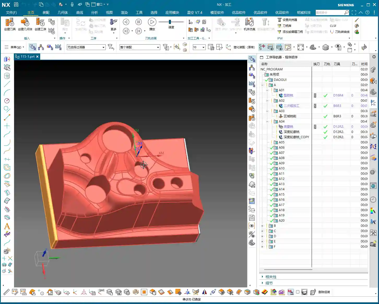
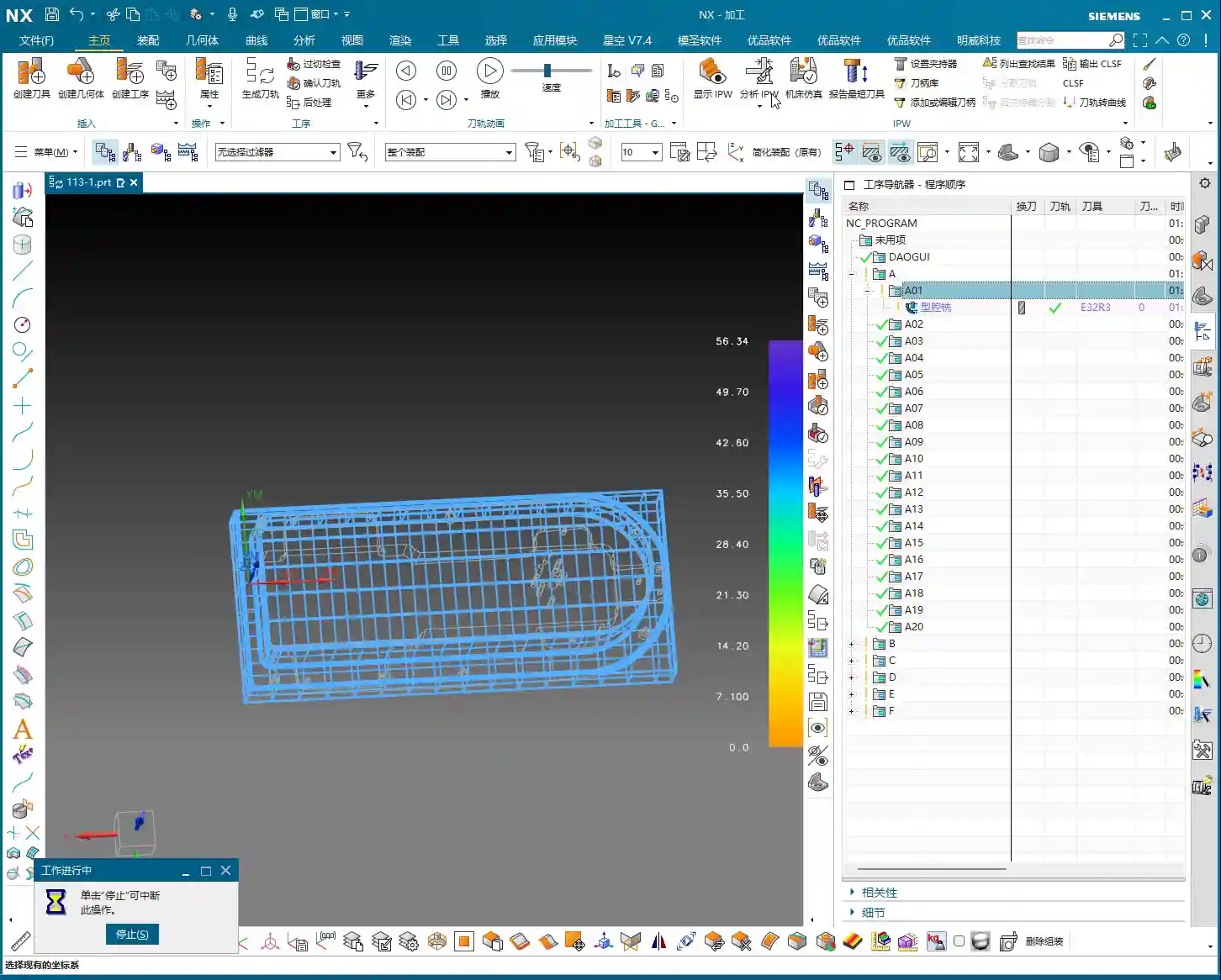
    Step One: Component Overview and Machining Strategy

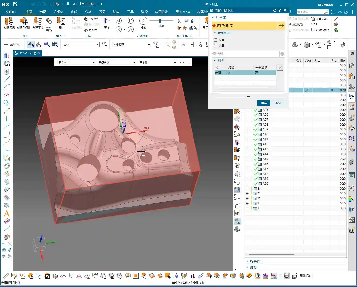
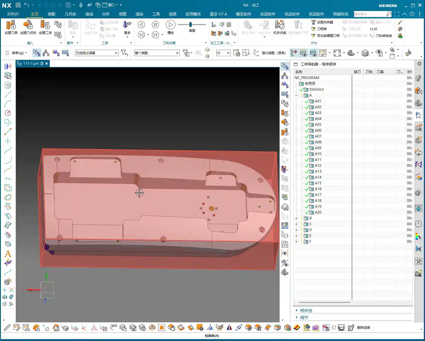
    The component we’re working with—while I might call it a “frame”—is actually a relatively small component. At first glance, it’s roughly 100+ by 50+ millimeters (approx. 4 x 2 inches), so not large. The customer provided a large blank, approximately 30 millimeters (approx. 1.2 inches) oversized compared to the finished part. Therefore, we need to understand this upfront: Sufficient material allowance for Roughing must be provided, but not blindly; it depends on the actual situation.

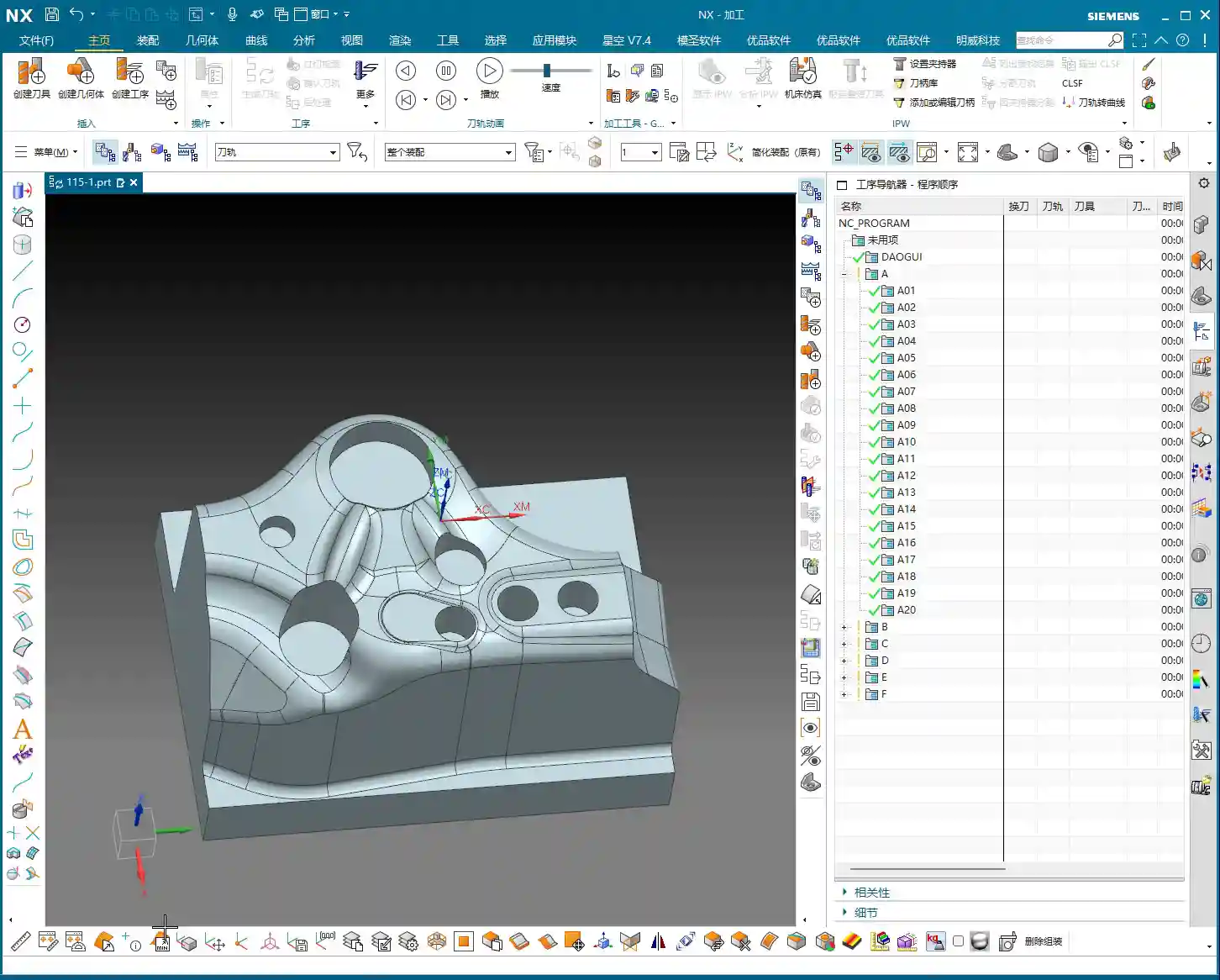
    My standard practice is to machine the bottom face first, then flip the part to machine the top face. Why? Once the bottom face is flat, it’s easier to establish datum features for the top face, and Clamping will be stable. This part has flat top and bottom surfaces; one side is straight, and the other has a slight taper. For parts of this geometry, we typically use a “sequential machining” approach in our workshop—machining one section first, then using it as a datum for machining the next.

    Upon analysis, all major faces of this component are flat; in Siemens NX, the surfaces appear uniformly green (indicating good quality). There are no particular pitfalls to watch out for. Those oddly shaped, uneven surfaces we’ve encountered before are not present here. So, at a macro level, we have a good grasp of the situation.

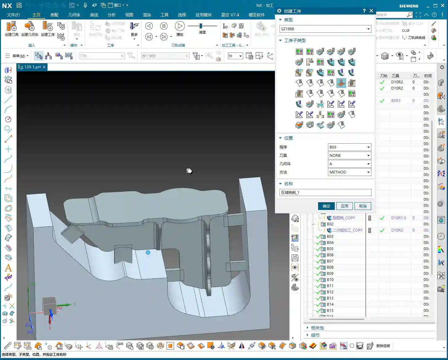
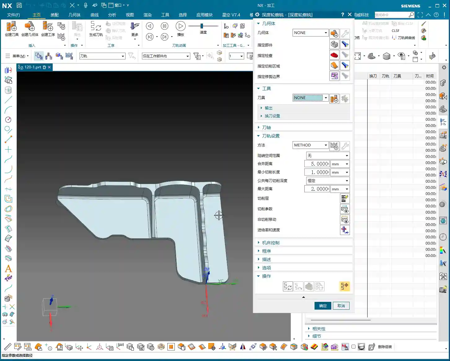
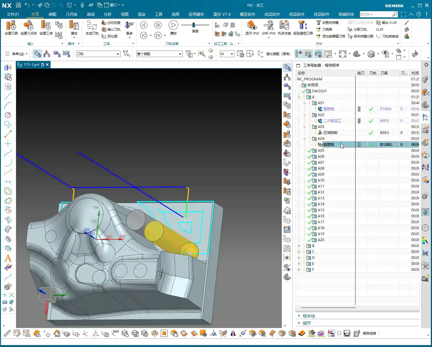
    Step Two: Tool Selection and Roughing/Finishing Strategy

    Before we start, tool selection is of paramount importance. It’s like going to war: if you have the wrong weapon, even the best skills are useless!

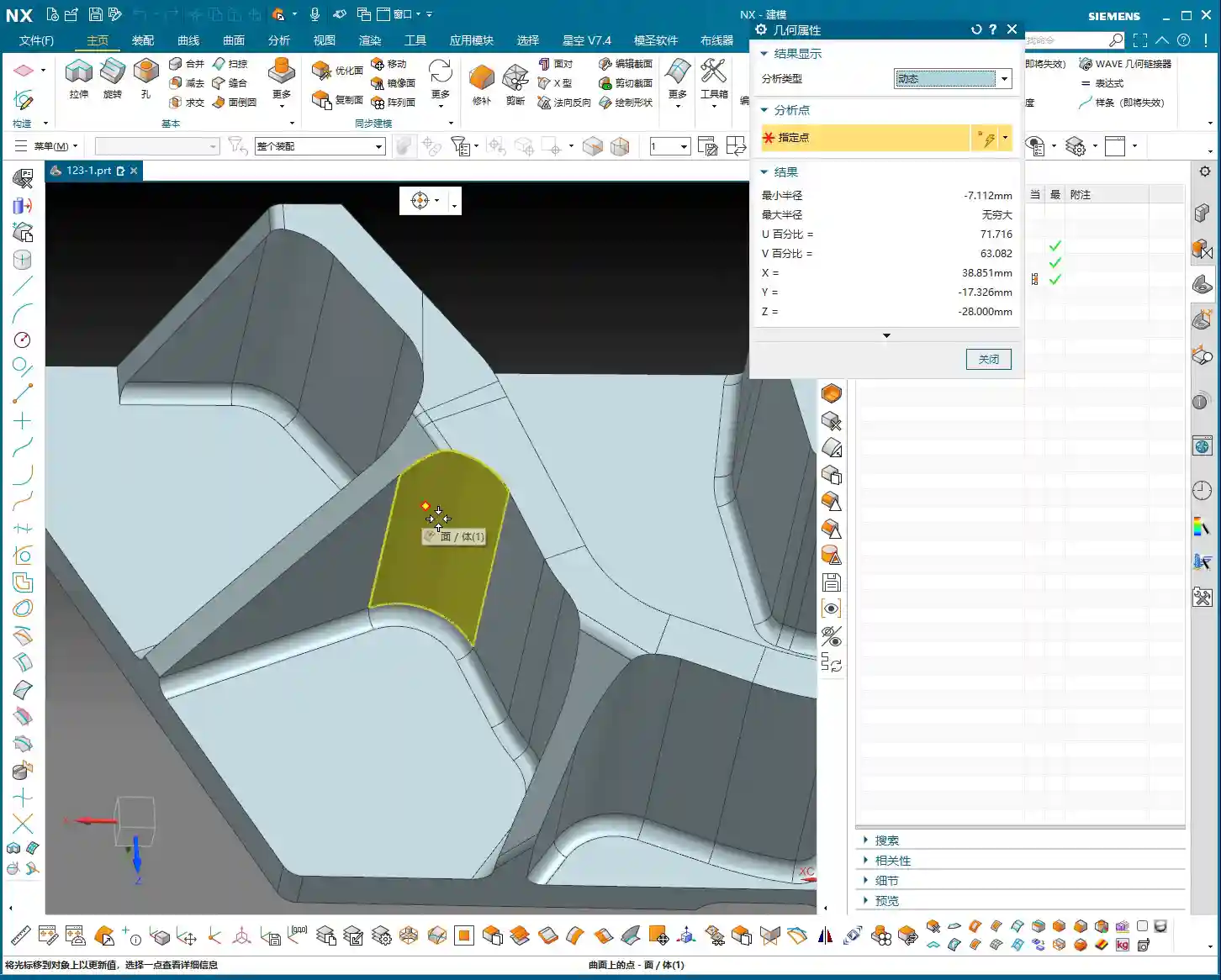
    Fillets and Tool Radii

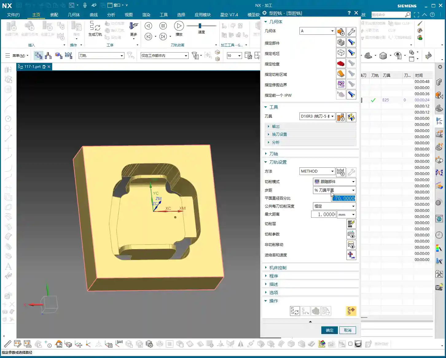
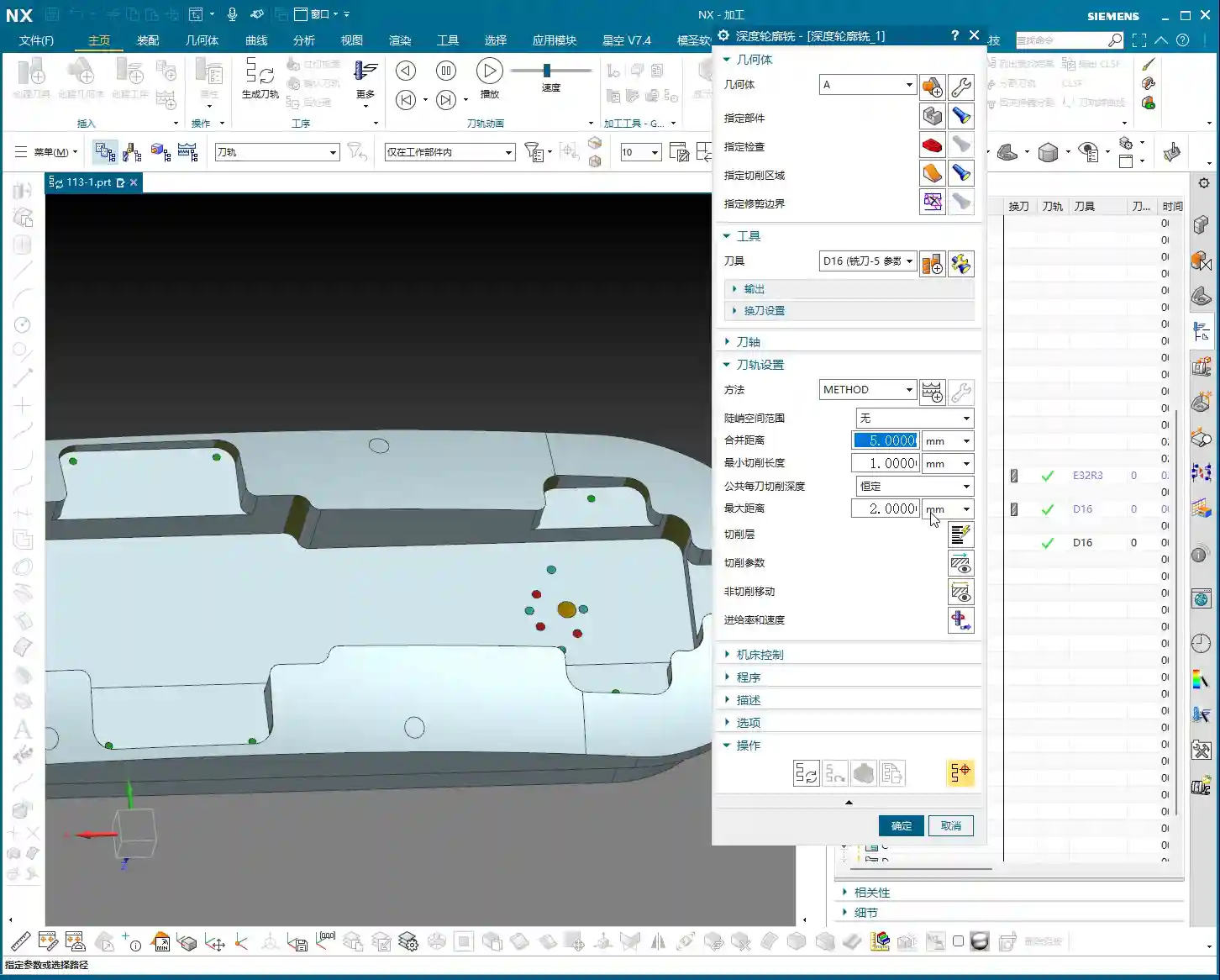
    Let’s take a close look at the part’s fillets. Most fillets are R1.5. However, at the connecting rib, a “Distance Analysis” in Siemens NX reveals it’s R7! Two R7s add up to 14mm (approx. 0.55 inch). So, using a D12 R1.5 (diameter 12mm, corner radius 1.5mm) ball end mill or corner radius end mill for a Finishing pass on the side walls and bottom is perfectly adequate, no problem.

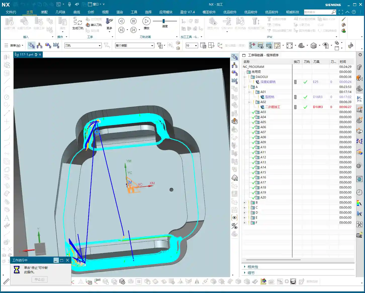
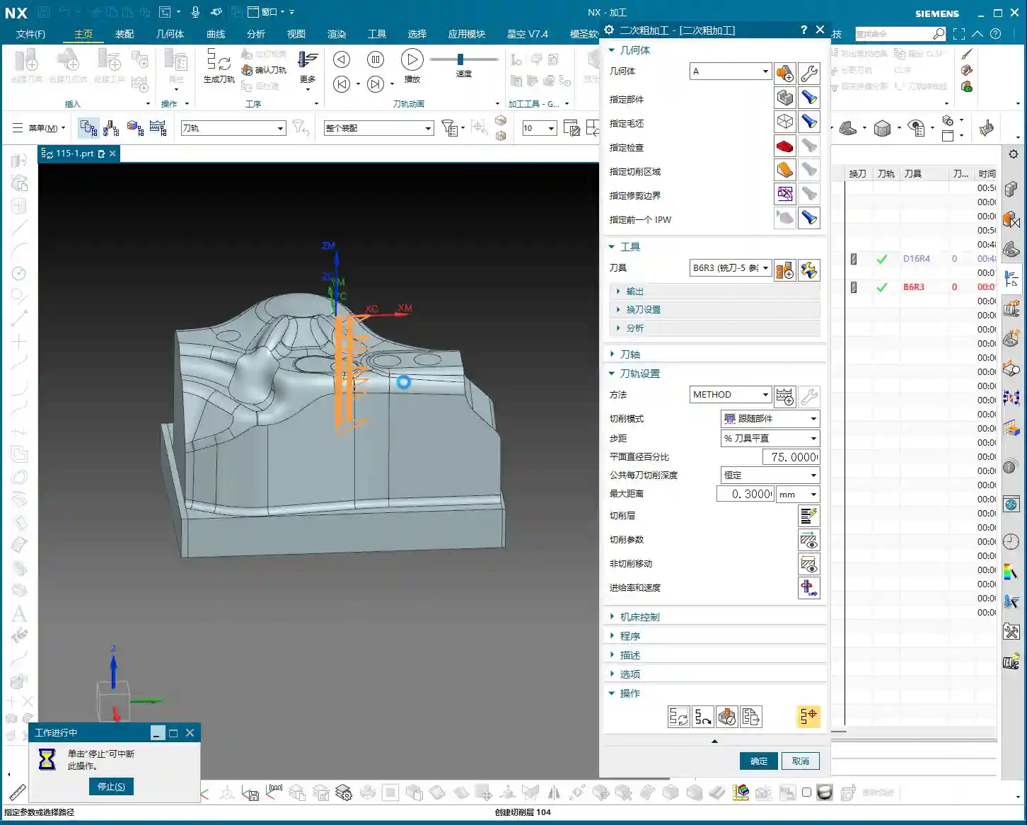
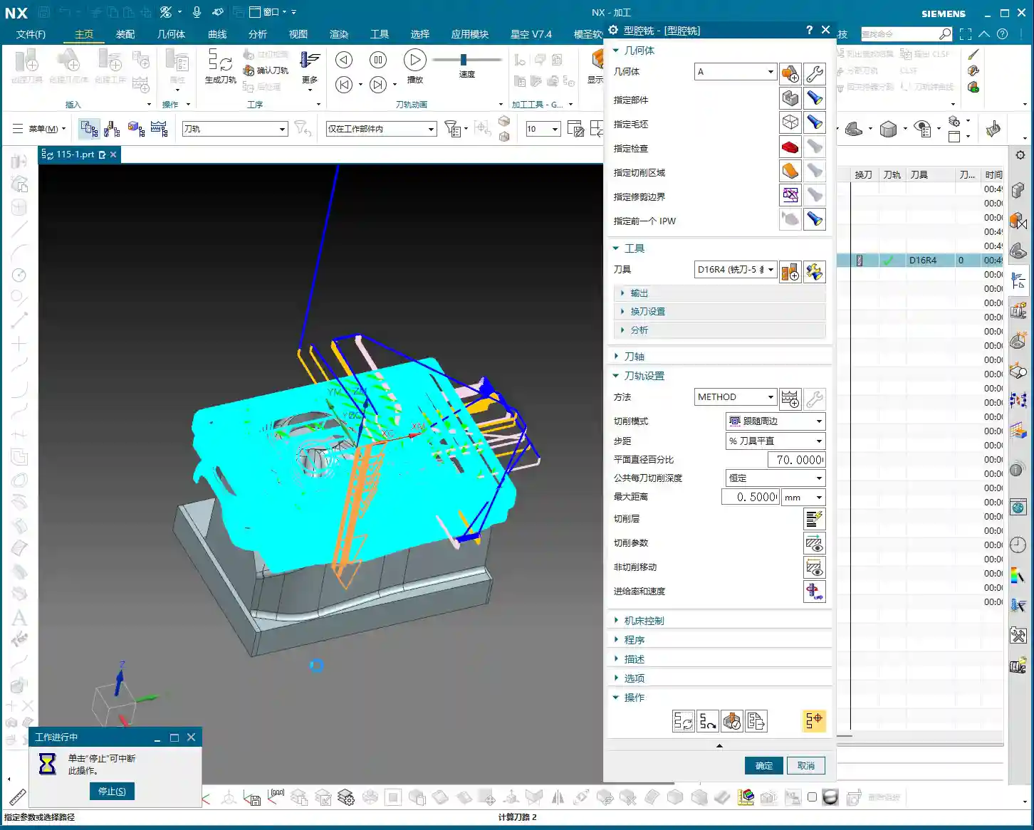
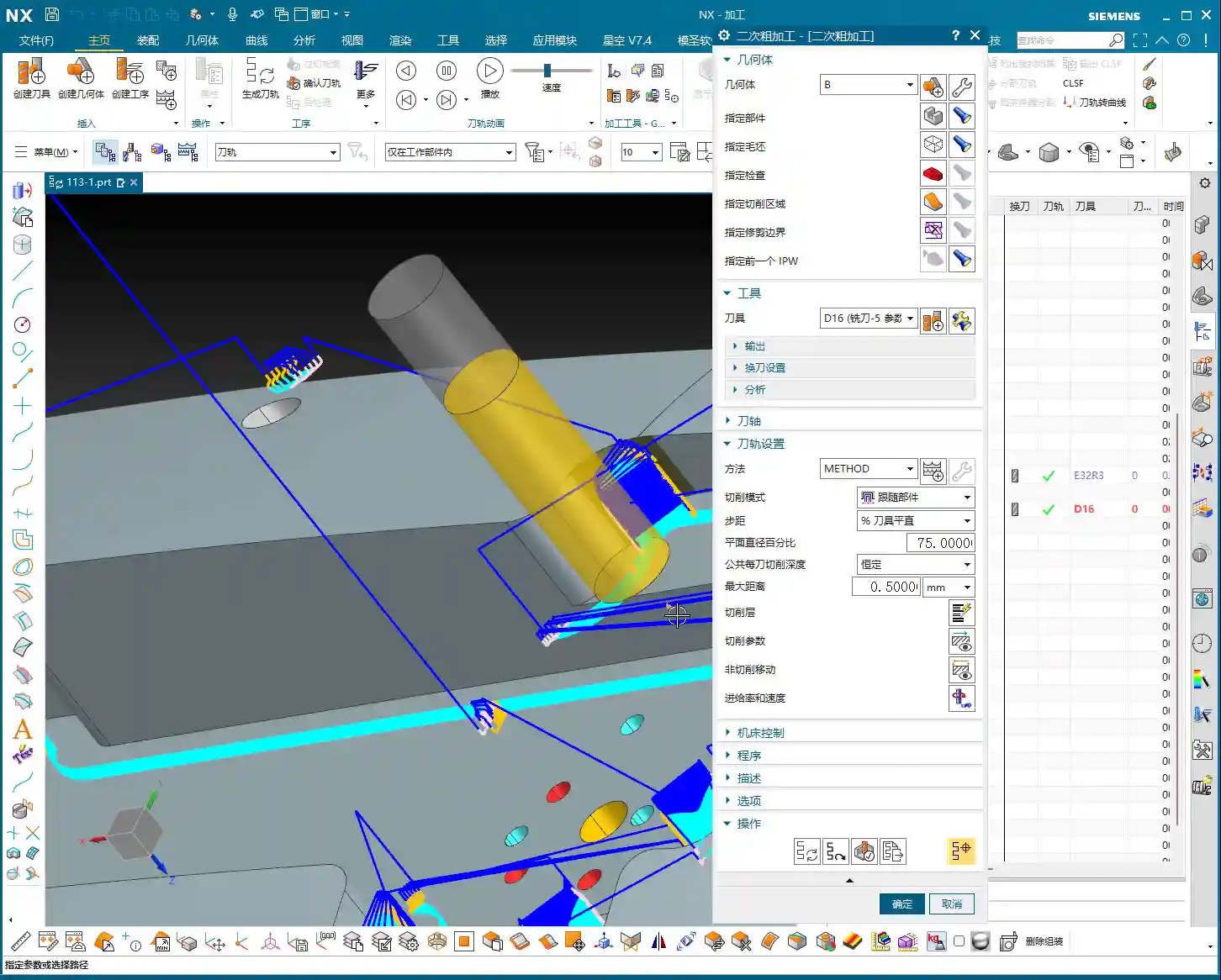
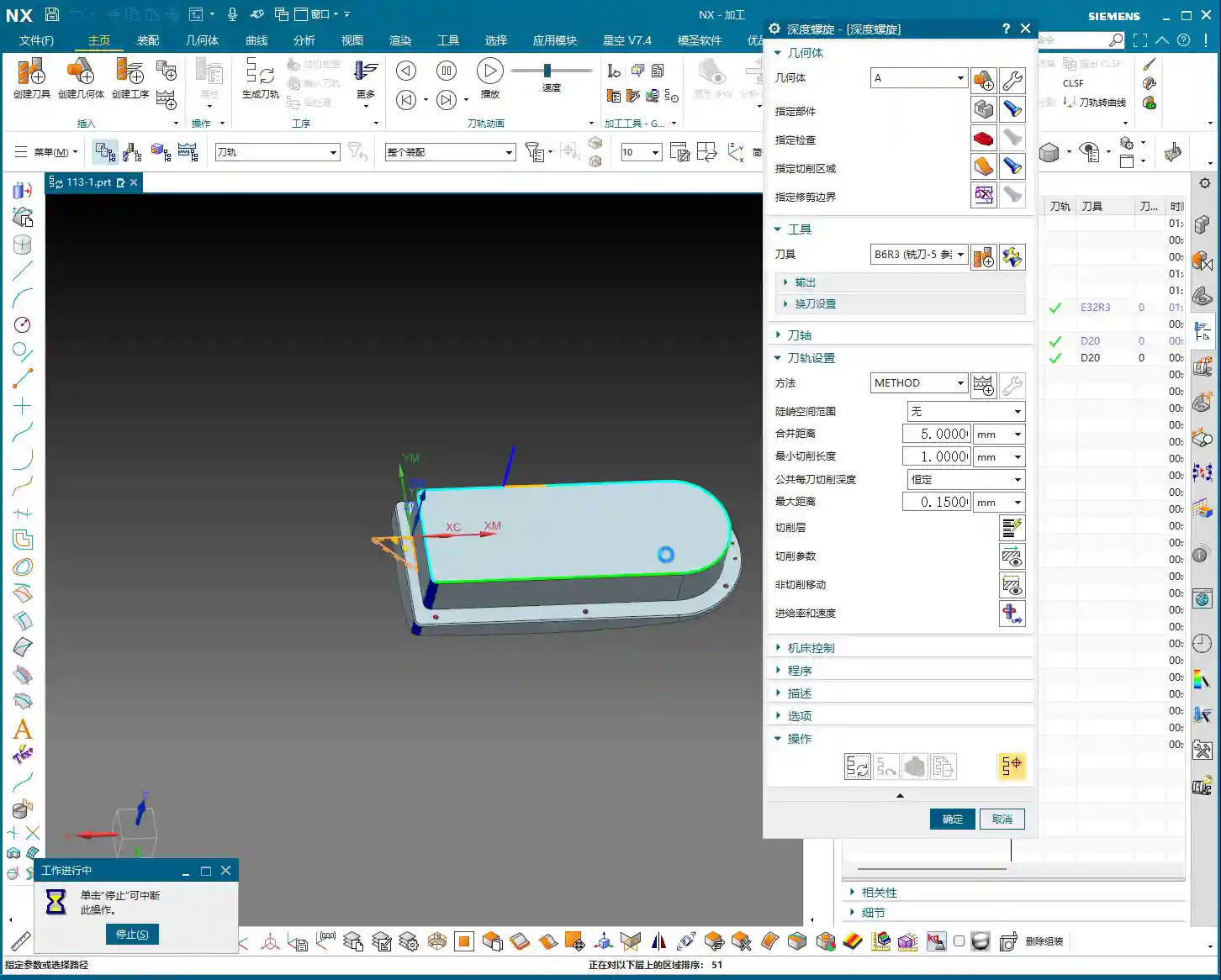
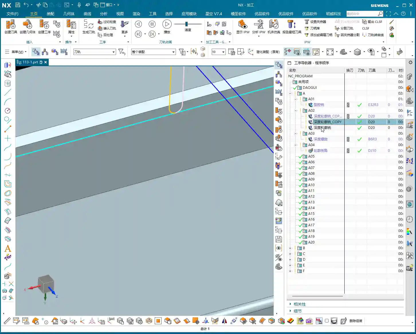
    Roughing and Cut-off Tools

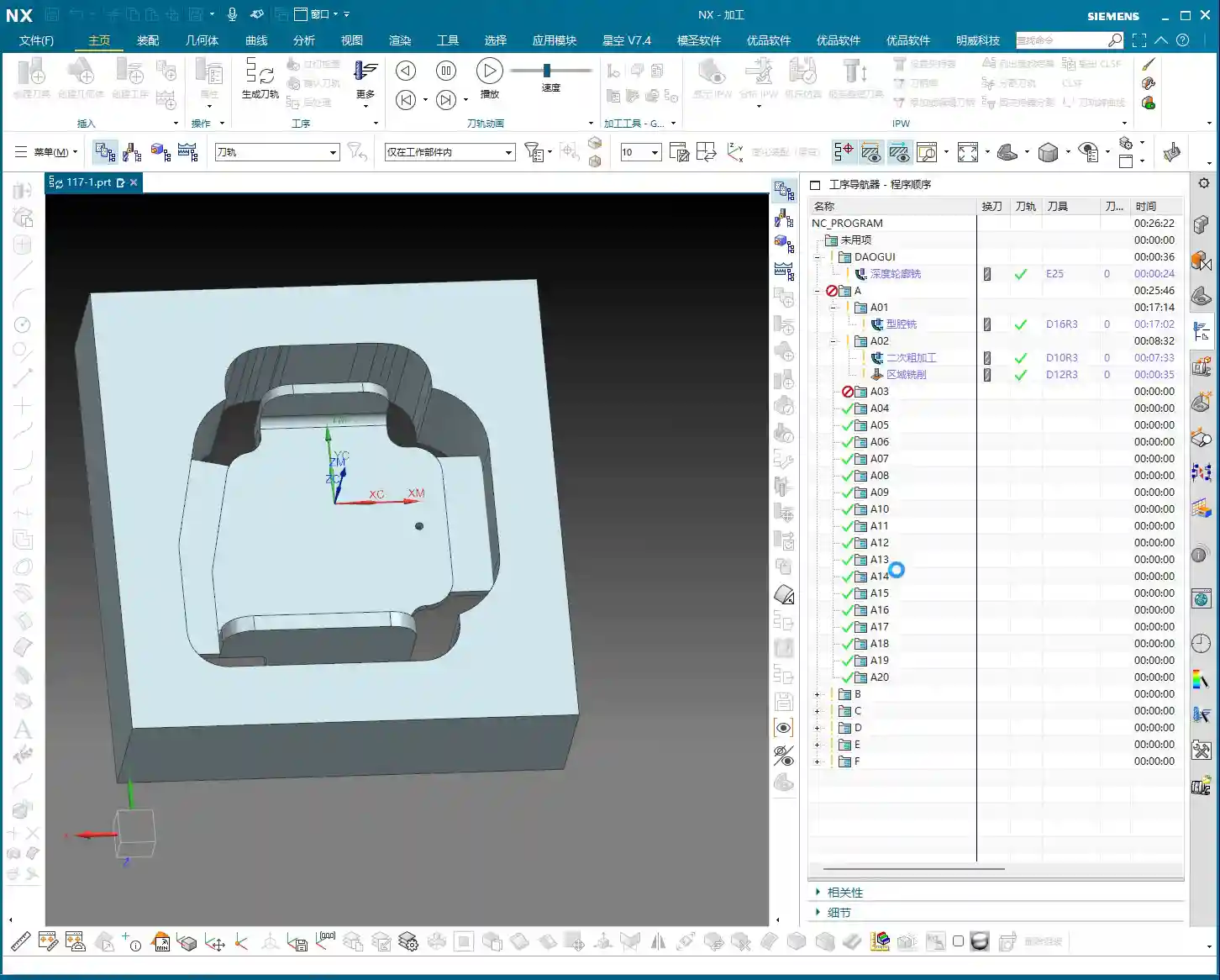
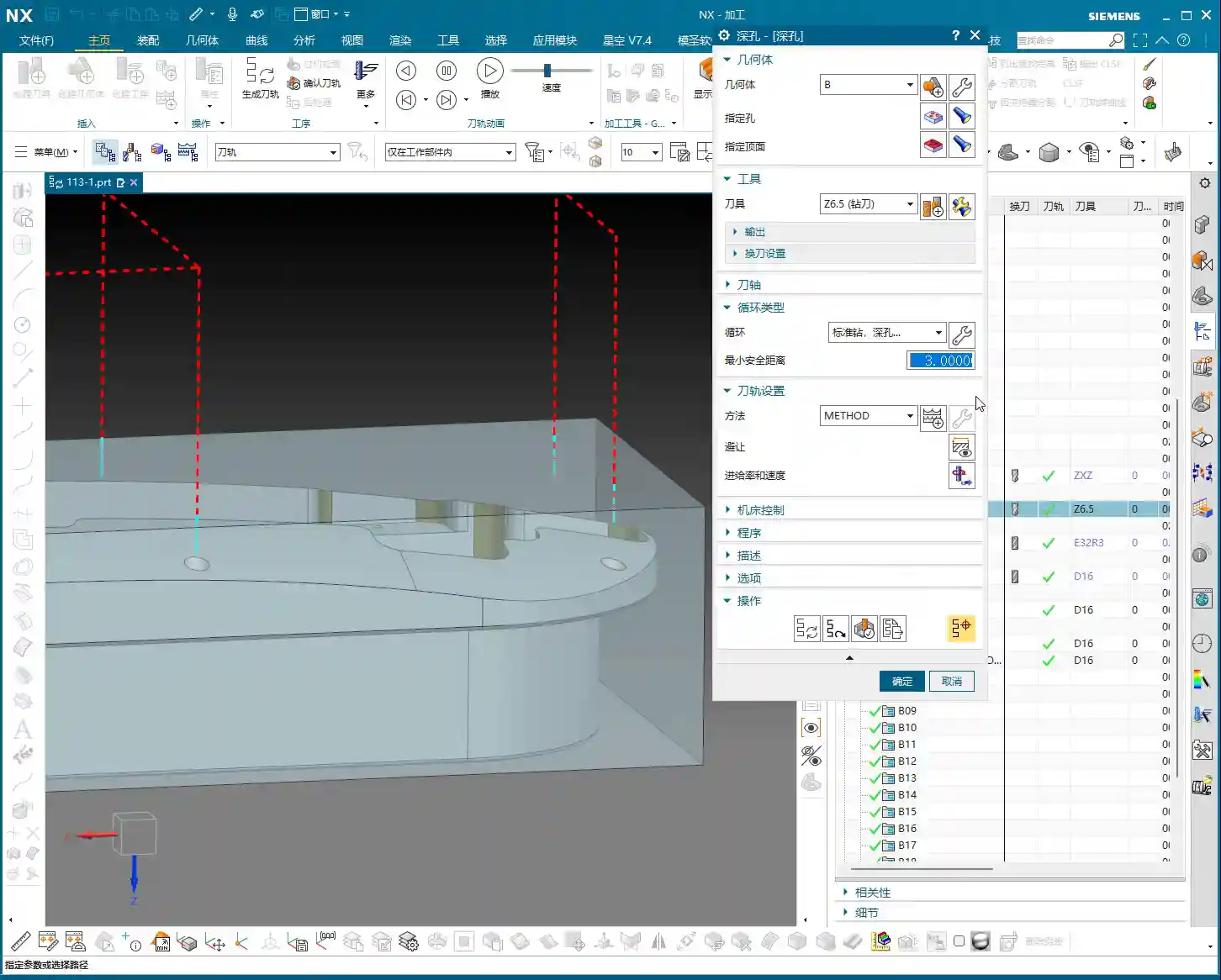
    For Roughing, we can use a slightly larger tool. The part is roughly 26mm (approx. 1 inch) wide, so a D20 (diameter 20mm) flat end mill or roughing end mill will run quickly and stably. As for the final cut-off operation, we typically use a D10 (diameter 10mm) tool. Keep this in mind, as it will allow for pre-planning during subsequent modeling.

    Step Three: Siemens NX Connecting Rib Modeling and Offset Techniques

    Now, for the main event—how to model these connecting ribs and prepare them for machining. Don’t just think a few clicks in Siemens NX will do the trick; there are many nuances here!

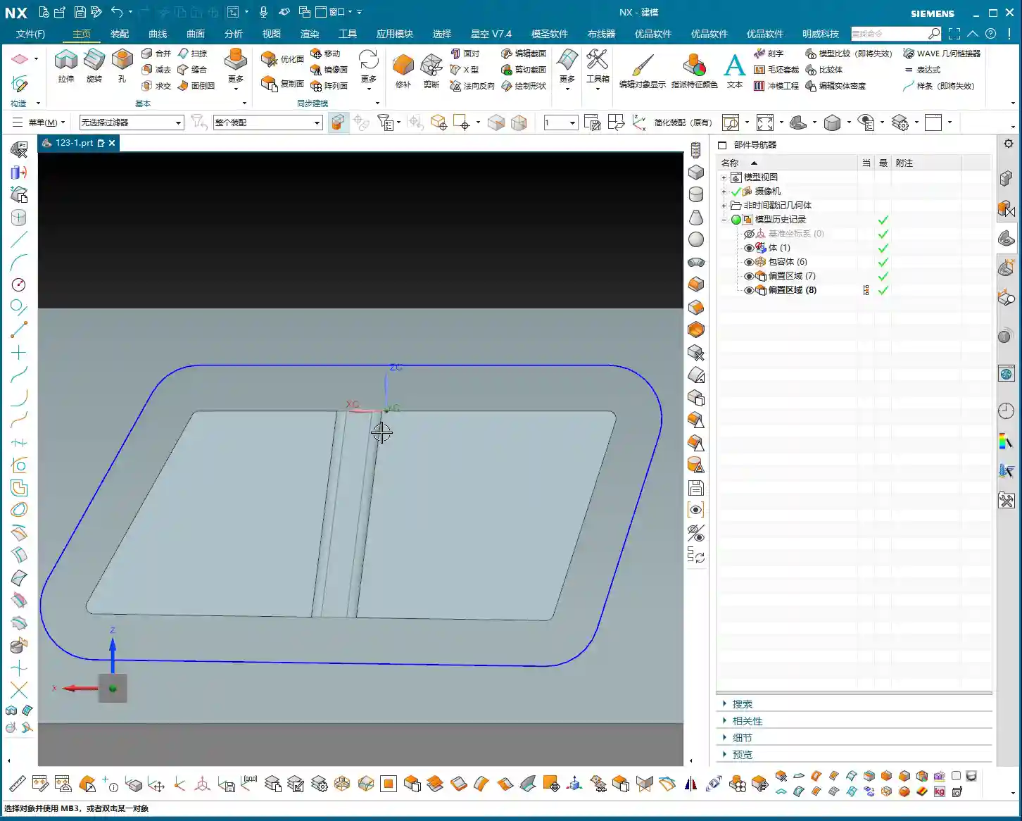
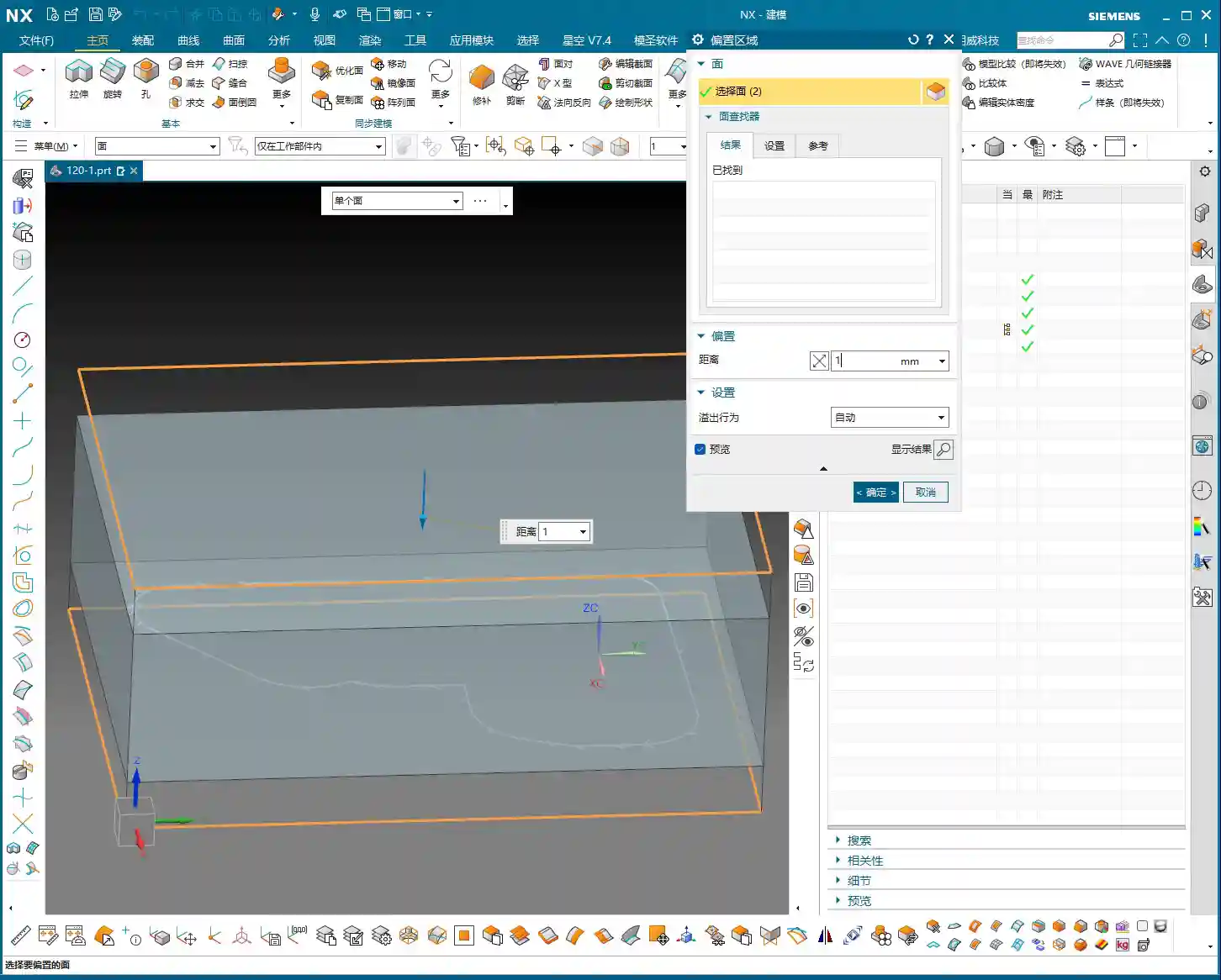
    Generating the Outer Contour

    First, we need to address the part’s outer contour. Using Siemens NX’s “Offset Curve” function, offset the lines on the model outwards. How much to offset is critical! If you use a 10mm (diameter 10mm) tool for cut-off and offset by 10mm, the tool centerline will be precisely on the contour line, resulting in zero allowance. The finish might be poor, or the tool might even chatter/gouge. Therefore, we offset by 12mm (approx. 0.47 inch). This allows the tool centerline to run externally, providing sufficient material allowance or leaving space for a Finishing pass, ensuring cutting stability.

    After offsetting, any previous auxiliary lines are no longer needed; delete them to keep the model clean. Then, remember to smooth the offset contour lines with fillets (e.g., R5) to avoid stress concentration from right-angle cutting. This benefits both the tool and the part.

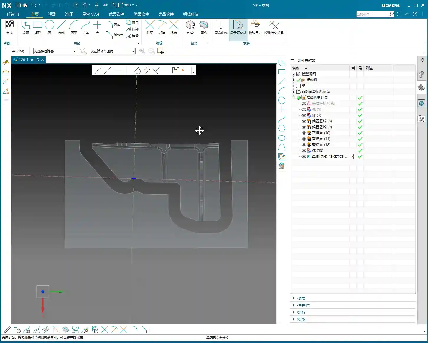
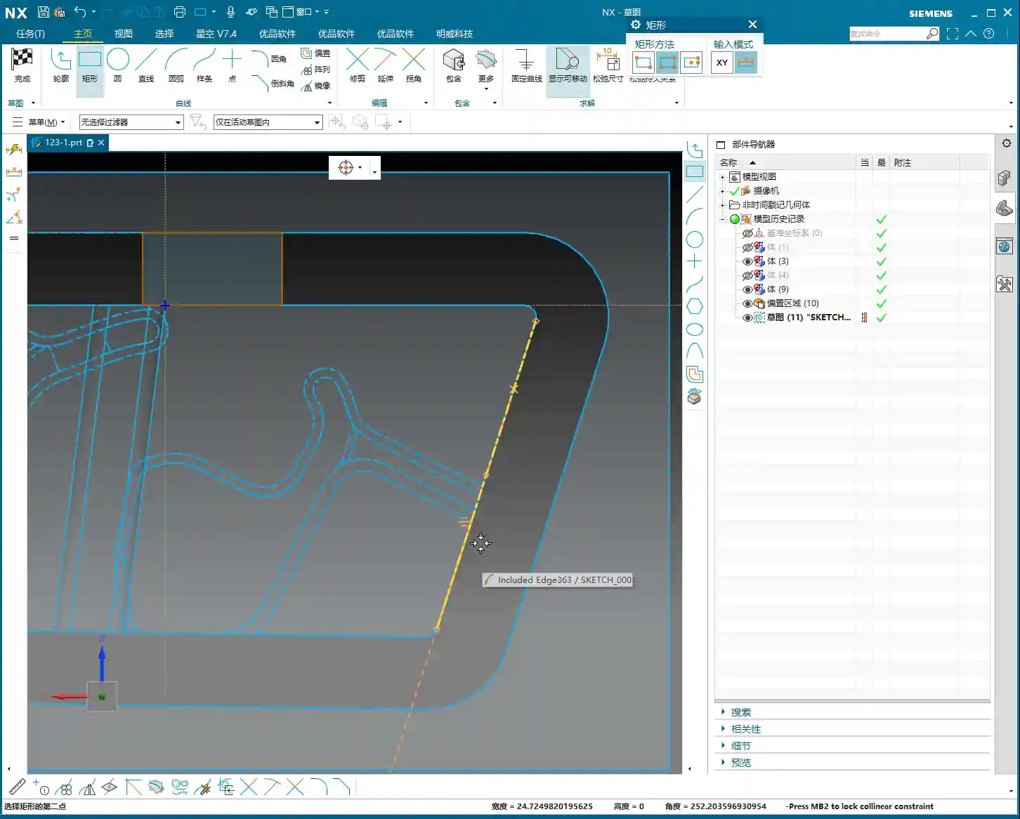
    Drawing and Extruding the Connecting Rib

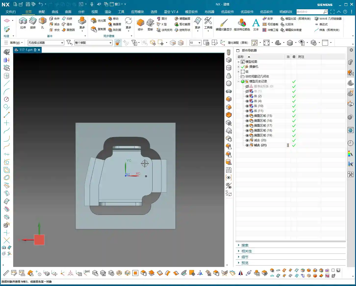
    Next, let’s draw the connecting rib. For this connecting rib, we’ll use the “Sketch” function to draw a rectangle on a reference plane. When drawing, ensure it extends to the part’s edge, as we’ll use it to “create geometry” later. Drawing it slightly larger is fine; it will be cut away eventually. The key is that its shape must be reasonable, providing connection and support.

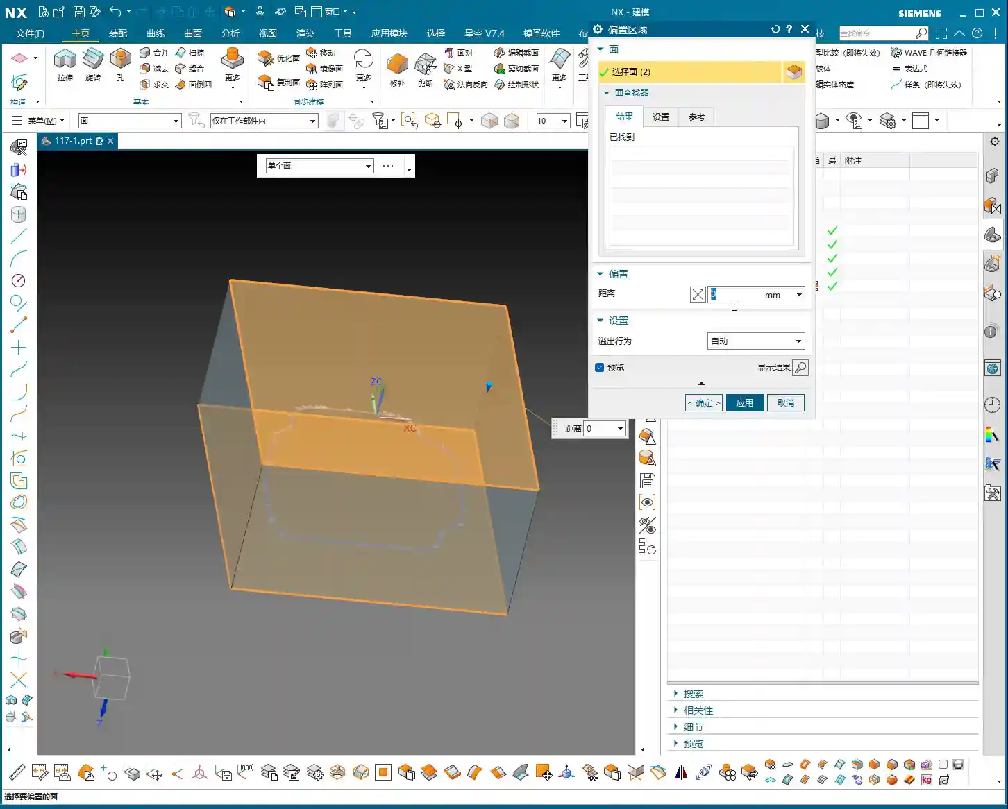
    After sketching, directly “Extrude” to create a solid body. If the extrusion height wasn’t precisely measured beforehand, just extrude it to an approximate thickness for now. This is where Siemens NX’s power lies—it can be adjusted later. After extrusion, you might find the top face of the connecting rib isn’t at the same height as other top faces of the part. No problem. Simply use the “Replace Face” function to replace the connecting rib’s top face with the part’s datum top face. This ensures all surfaces are on the same plane, saving you the hassle of multiple measurements and adjustments.

    Finally, if any auxiliary curves generated during the extrusion are no longer needed, delete them. Can’t delete them? Throw them into a junk layer (like my 252 layer)—out of sight, out of mind! These are all small tips for boosting work efficiency.

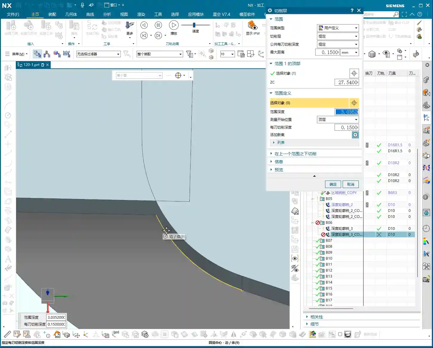
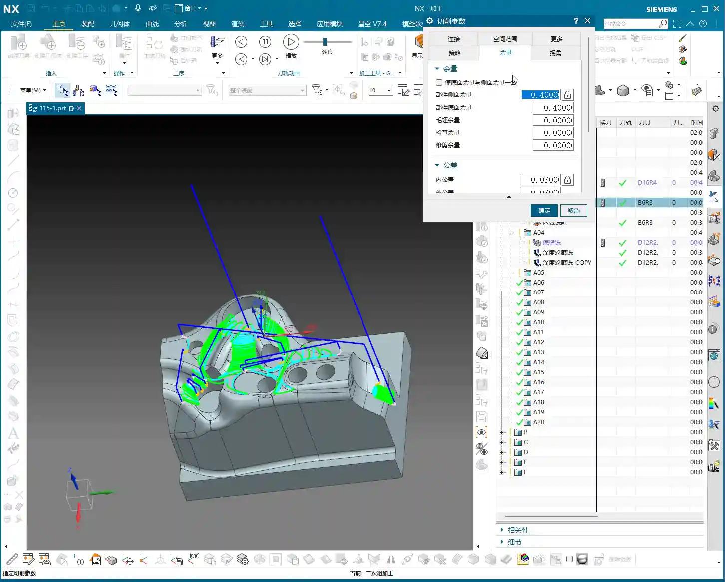
    Step Four: Surface Handling and Parameter Management

    Surface handling and parameter management are easily overlooked but highly critical aspects of Siemens NX operations.

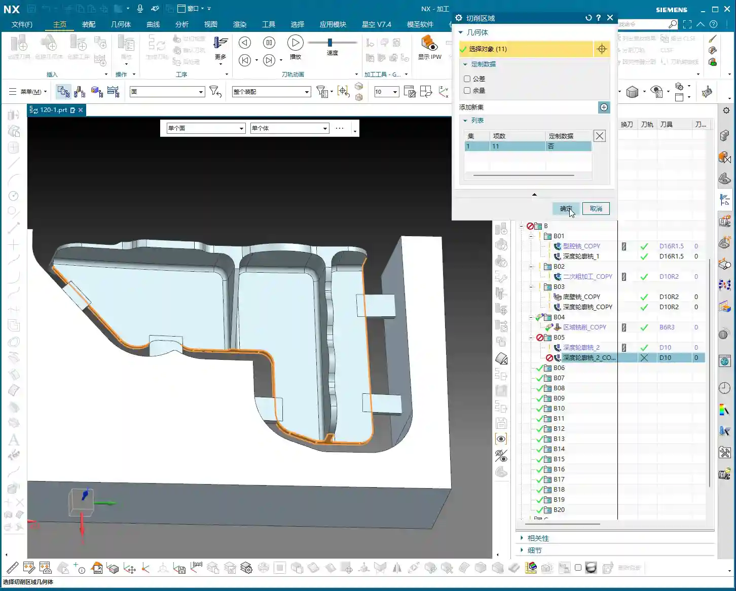
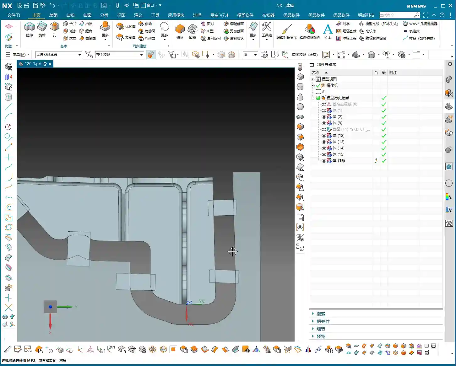
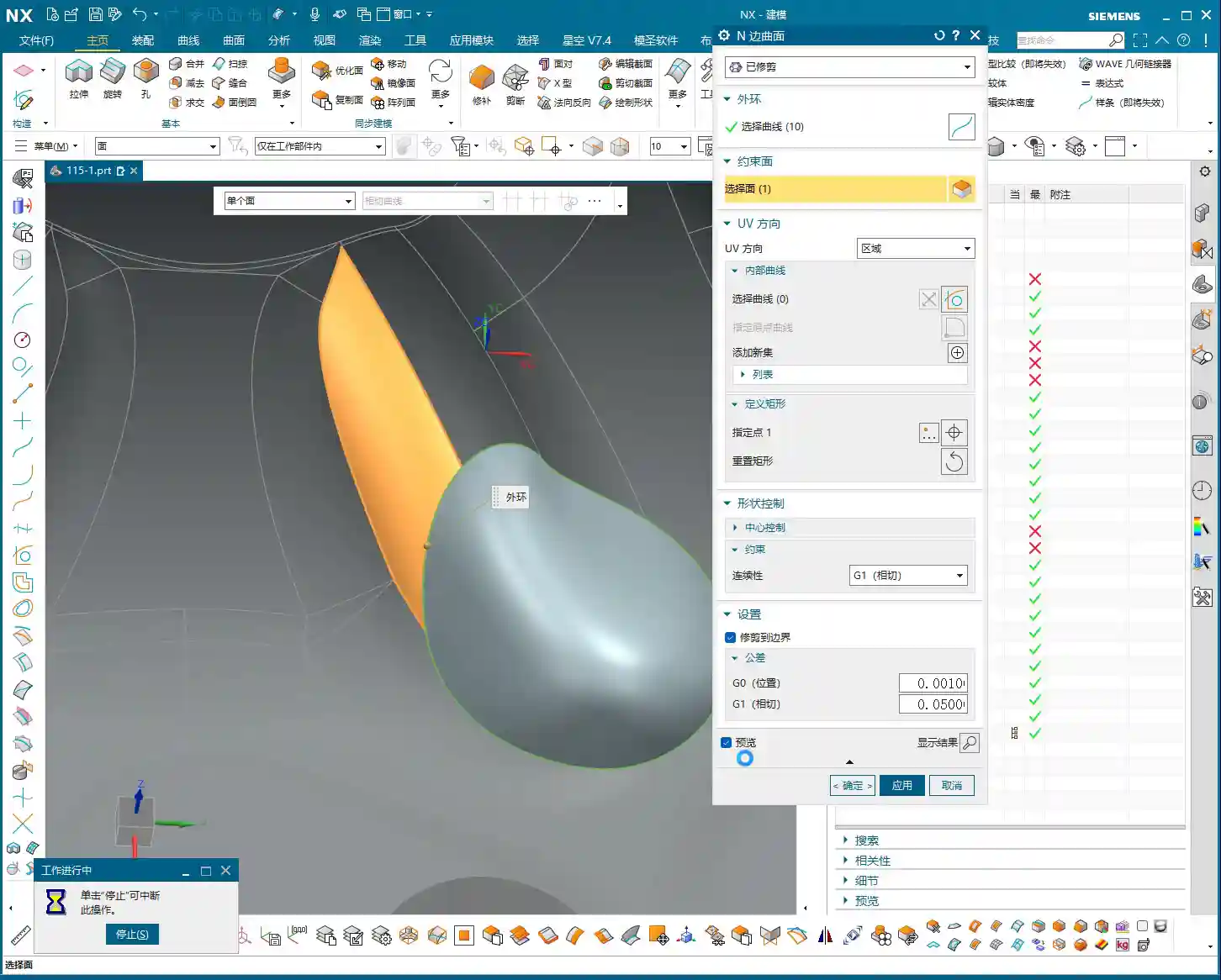
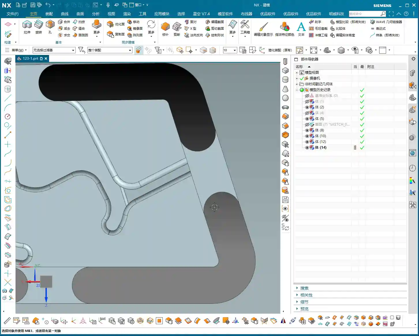
    Surface Smoothing and Splitting

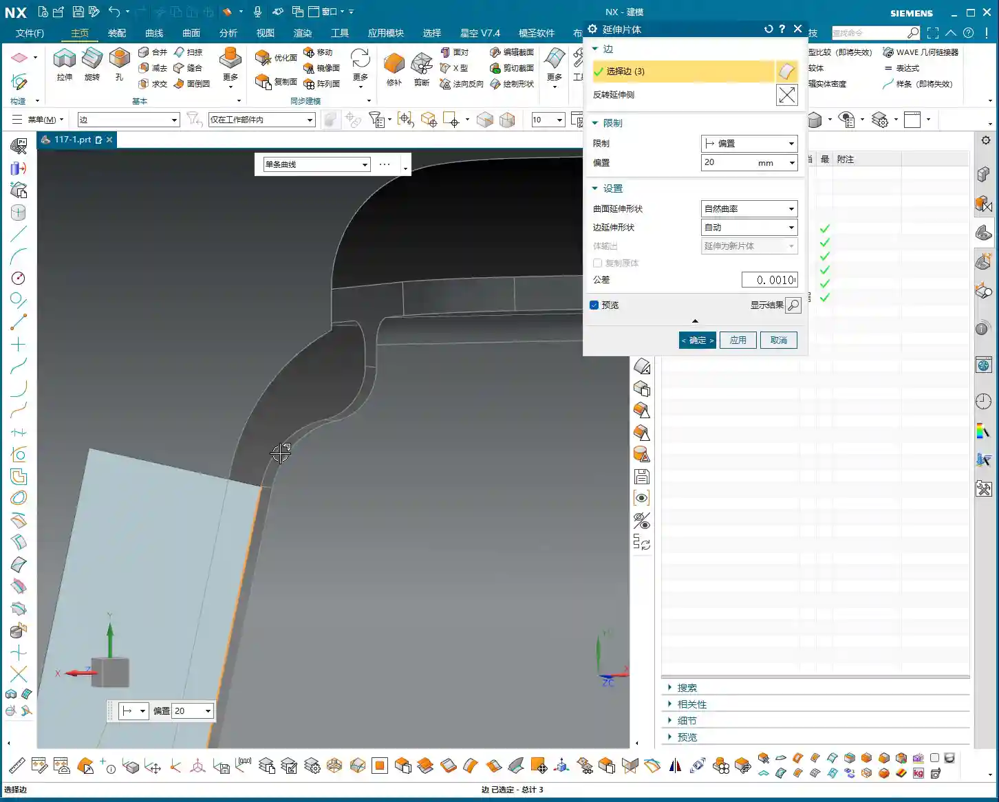
    When modeling connecting ribs, I recommend using arcs to connect linear segments for smoother transitions. This isn’t just for aesthetics; it’s crucial for machining. Smooth transitions enable more fluid tool engagement, reduce Chatter, extend tool life, and improve the part’s surface finish. Don’t underestimate this small arc; it can save you significant polishing and grinding time!

    Additionally, for areas requiring independent machining, such as the bottom of the connecting rib, we can use the “Split Face” function to divide a large face into several smaller ones. This allows for more precise toolpath control during programming—for instance, machining only this small area instead of traversing the entire face. This is highly valuable for controlling machining boundaries and optimizing efficiency.

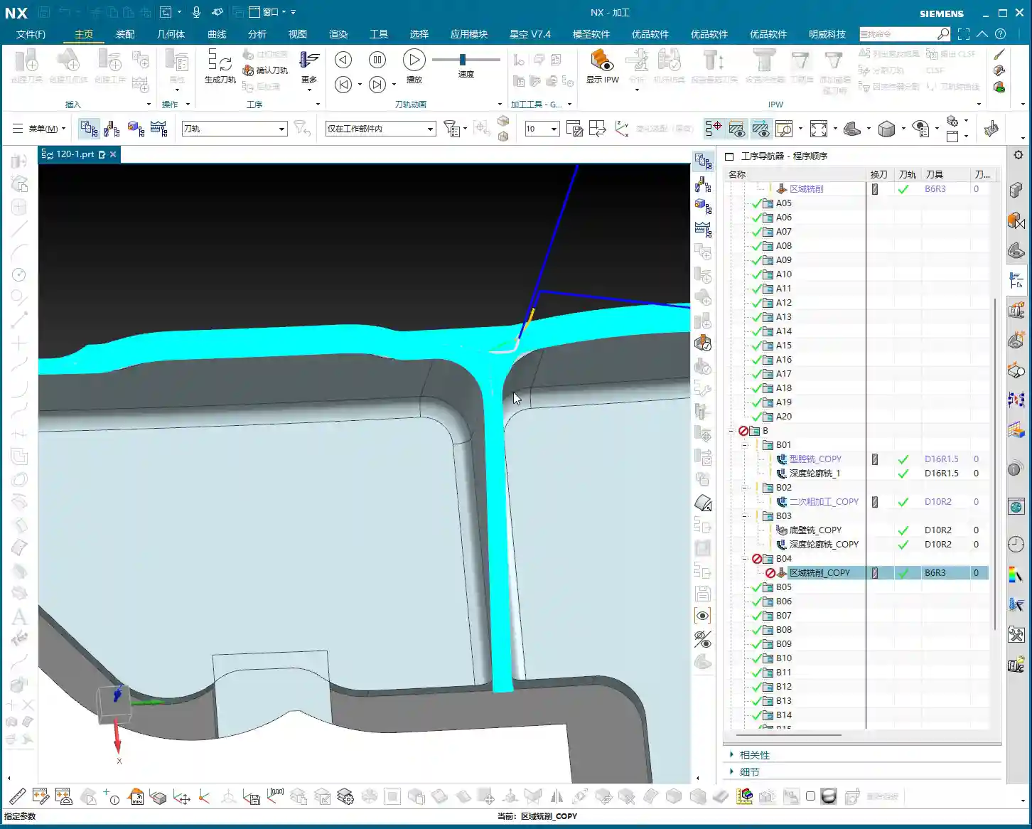
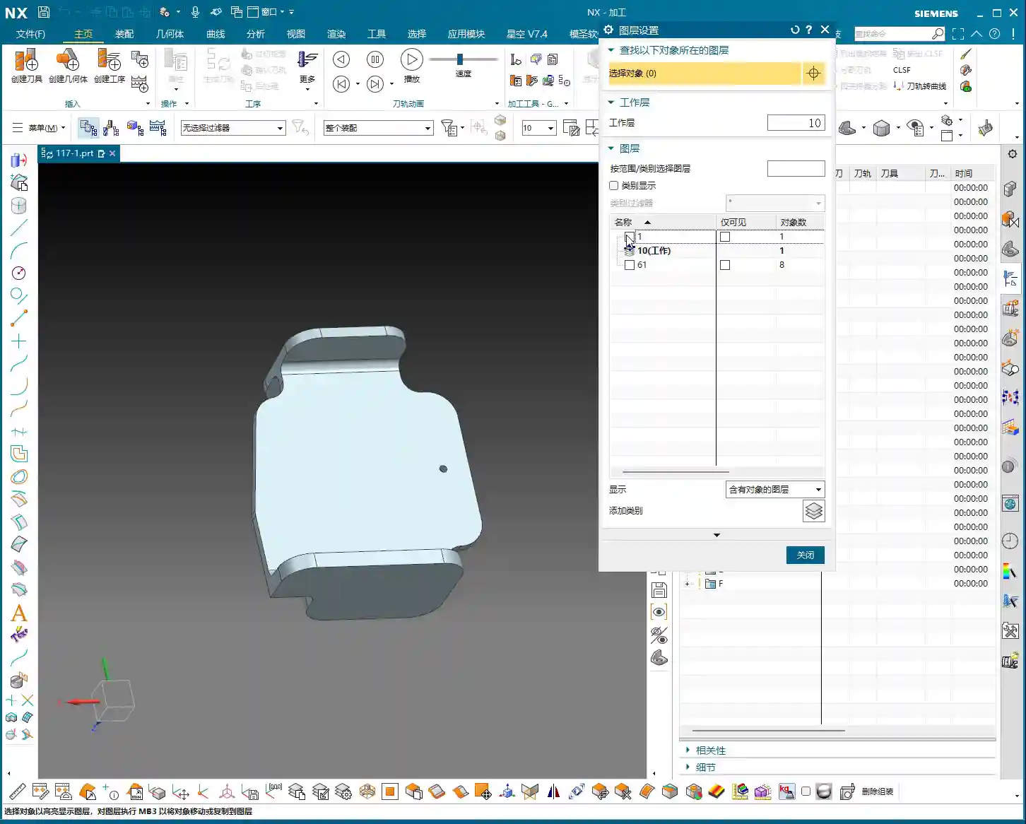
    Layer Management and Model Standards

    Siemens NX’s layer management is an excellent feature; you must use it! My practice is to place:

    • Blanks/Raw Material on layer 100
    • Finished Parts on layer 10
    • Connecting Ribs on layer 200
    • Unused auxiliary lines and junk features on 252 (junk layer)

    This way, the model structure is clear at a glance; just activate the layers you need, avoiding model clutter and difficulty in searching. Don’t underestimate these details; standardized layer management can double your work efficiency and facilitate collaborative work. It’s a cornerstone of efficient teamwork and an embodiment of “standardization” in industrial product management and promotion, which can lead to a better market reputation for your products!

    Summary: Pitfall Avoidance Guide

    1. Proper Blank Allowance is Crucial: Never underestimate the raw material allowance. It directly impacts Roughing efficiency and subsequent machining accuracy. Too little, and you can’t cut; too much, and you waste material and time.
    2. Matching Tool Selection is Key: Choose tools based on the part’s fillets, dimensions, and operations (Roughing, Finishing, cut-off). Incorrect tool selection can lead to low efficiency at best, and scrapped workpieces or broken tools at worst. For example, offsetting for cut-off by 12mm instead of 10mm is to provide the tool with sufficient cutting space, preventing it from cutting directly on the contour line, which could lead to unstable cutting or even breakage.
    3. Smooth Connecting Rib Modeling: Proper transitions between lines and arcs not only enhance aesthetics but are also critical for ensuring smooth machining and reduced tool wear.
    4. Flat Surfaces are Fundamental: Make full use of functions like “Replace Face” to ensure all machined surfaces are on the same plane, avoiding issues like secondary Tool Offsetting or accuracy problems caused by uneven surfaces.
    5. Layer Management is Indispensable: Develop good layer management habits. This not only makes finding files easier for you but also allows colleagues to quickly take over. This is the cornerstone of efficient teamwork and an embodiment of “standardization” in industrial product management and promotion, which can lead to a better market reputation for your products!

    **[EXCERPT]**
    Master Wang discusses efficient connecting rib machining in Siemens NX. He analyzes the part blank and plans roughing and finishing tools (D12 R1.5 for R7 fillets, D20 for Roughing, D10 for cut-off). He demonstrates Siemens NX offset curves and surface replacement, emphasizing a 12mm offset to avoid air cuts. He teaches connecting rib sketching, extrusion, and arc smoothing techniques, combined with standardized layer management, to achieve efficient and precise machining, sharing practical experience in avoiding pitfalls.

    👤 About the Author:
    The author is a veteran CNC machining professional with 15 years of industry experience, specializing in UG NX programming. This article is an original work representing personal practical insights.

    ⚠️ Copyright Notice: Unauthorized reproduction or distribution without prior communication is strictly prohibited.

  • Real-world Siemens NX Two-Stage Programming for Webs: Master Wang Helps You Conquer Stock Allowance

    📝 Key Takeaways:

    Mastering Two-Stage Programming for Webs

    Pr…

    [VIDEO_HERE]

    Preface: Why Two-Stage Programming?

    Hello everyone, I’m Master Wang. I’ve been in the machining industry for fifteen years, and I’ve seen it all—turning, milling, planing, grinding, EDM. Siemens NX programming is second nature to me. Today, we’re not going to talk theory; instead, we’ll dive into the web machining of this part and discuss how to master two-stage programming, especially those real-world tricks you won’t learn from textbooks. We’ve already finished machining Side A of the part, so now, let’s flip it over and tackle Side B. Listen closely, because these are genuine, hard-earned insights!

    Side B Work Coordinate System and Stock Definition: Getting Started Right

    First, you need to create the Work Coordinate System for Side B. Select your B-axis for the setup, then specify a plane, for example, by inputting a distance of 100mm, and establish its position. This is the absolute basics; if your Work Coordinate System isn’t set up correctly, your tool will get “lost,” and every path will be wrong.

    Next up is the stock. While I often say that programs can be copied and pasted for convenience and speed, you absolutely must re-verify the stock selection after copying. Especially in multi-sided machining, the stock geometry varies in different orientations. If the stock is selected incorrectly, the program might still generate, but the resulting part will be vastly different from what you intended—a complete waste of effort!

    Roughing Strategy: Digging into Details, Avoiding Pitfalls

    Two-Stage Roughing: The Wisdom of Layered Progression

    For structures like webs that require significant material removal, we typically adopt a two-stage roughing strategy: “first roughing pass” and “second roughing pass.” Simply put, first use a large tool with a significant Depth of Cut (DOC) to remove most of the material (first roughing pass), then switch to a smaller tool, or reduce the Depth of Cut, to more carefully remove the remaining material (second roughing pass), preparing for the subsequent Finishing pass.

    As I always say, “For roughing, first rough it down to the bottom, then follow up with a second roughing pass.” The goal is clear: ensure efficiency while effectively controlling tool wear and preventing excessive cutting loads in a single pass that could lead to chipped or broken tools.

    Stock Allowance Control and Toolpath Depth: Striving for Perfection

    During roughing, many people like to mill a bit deeper, perhaps an extra 1.5mm or 2.2mm, thinking it’s safer. This is a good habit for ensuring complete material removal. However, there’s a “pitfall” you need to watch out for:

    • Master Wang Reveals:“Milling excessively deep is often pointless, because the tool is too large.” Understand? You can set any depth in the software, but in reality, if your tool size is relatively large, or if the part’s geometry is restrictive, the tool simply cannot reach that depth. The extra depth you set won’t be cut, just wasting calculation time. So, don’t just rely on software simulation; look at the cutting sparks!
    • Core Principle: For the first roughing pass, you only need to ensure efficient removal of the bulk material; don’t overthink that extra bit of milling depth. The precise depth control is truly needed during the second roughing pass. At this stage, we’ll consider going “an extra 2.2mm or so,” because the tool is relatively smaller and can reach the desired depth more effectively.
    • Master Wang’s Reminder: Especially in complex structures like webs, which are prone to dead ends, “this area is prone to heavy cutting loads,” so toolpaths must be carefully controlled to avoid overload.

    Residual Stock Removal: Leaving No Dead Ends

    After roughing, there are always some areas where, due to tool size limitations or complex geometry, some “internal residual stock” remains (audio 3:26). If these remnants aren’t thoroughly cleaned up, they’ll cause problems for the subsequent Finishing pass.

    For this residual stock, we typically use specialized toolpath strategies, such as “Deep Profile Milling” or “Hybrid Milling,” using smaller tools for Corner Cleanup or Rest Milling.

    Master Wang’s Experience: This is a crucial detail: “It’s best not to set it to zero stock; if you do, toolpaths will also appear on the exterior.” What does this mean? It means that at the edges of the roughing pass, do not set the stock allowance to 0mm. Even leaving a 0.05mm stock allowance can significantly reduce the risk of the tool scratching the workpiece edges, preventing burrs. This is a practical trick you won’t learn from textbooks, and it can save you a lot of rework time and money!

    Of course, for external contours that do not connect to subsequent finishing surfaces, you can choose to leave no stock allowance and mill directly to size; that’s perfectly fine.

    Finishing Process: The Secrets of Surface Finish

    Tool Selection and Feed Strategy: Pursuing Perfection

    Finishing pass, as the name suggests, aims for optimal surface finish and dimensional accuracy. Therefore, we typically select tools with smaller radii, such as the R1.5 or R2 ball nose or bull nose end mills that I frequently use.

    For toolpath strategy, the Finishing pass often opts to “feed in from the outside, milling inwards for the finish cut.” This avoids the impact and tool marks that can occur when a tool directly plunges into the interior of the workpiece, ensuring consistent surface quality.

    Master Wang’s Tip: During the Finishing pass, the stock allowance for most curved surfaces or side walls will be set to 0mm to ensure final dimensions. However, for transition areas connecting the bottom and side walls, a small amount of stock allowance (e.g., 0.1mm) is sometimes left for better blending and to avoid overcutting, then smoothed out with strategies like “Hybrid Milling.”

    Avoiding Finishing Pitfalls: The Double Toolpath Issue

    When programming Finishing passes, you might sometimes notice “two layers of toolpaths” in the software simulation (audio 9:28), even though you only intended for one. This is a common “illusion” and “pitfall” that many people encounter.

    Master Wang’s Analysis: Double toolpaths usually occur due to improper datum height or thickness parameter settings. The software interprets a certain height as a datum, then generates an additional layer based on your parameters. This is extremely dangerous in actual machining and can lead to overcutting, air cutting, or even scrapping the part directly!

    Solution: When this happens, we must immediately check and adjust the thickness parameter. For example, change the thickness from its default value to a smaller number, such as 0.1mm. As long as this thickness setting is reasonable and distinct from the actual part height, the extra toolpaths will immediately disappear, leaving only the single layer you intended.

    Master Wang Emphasizes: “If their heights are different, just reduce it a bit”—this principle applies to many similar scenarios. The core idea is to tell the software what your true machining depth or boundary is.

    Program Reuse and Optimization: Efficiency Above All

    Copying and Modifying: The Siemens NX Programming Shortcut

    In practical work, if a part has many similar features, or like our example today, a single part has multiple machining faces, copying existing programs is the most direct way to boost programming efficiency.

    Master Wang’s Experience: Copying and pasting is great, but never get lazy. After each copy, you must carefully inspect and modify several core parameters:

    • Stock Definition: Ensure it corresponds to the current machining state.
    • Machining Face Selection: Re-select the correct machining area.
    • Toolpath Depth and Stock Allowance: Adjust according to the roughing and finishing stages and specific requirements.
    • Boundary Type: For example, whether to feed in from the outside or inside, and if extension is needed.

    Master Wang’s Maxim: “If programs are highly similar, feel free to copy them, but the devil is in the details!” Oversights in minor details are often what lead to rework or even scrapped parts.

    Considerations for Machining Sequence: Rough First, Then Finish; Bottom First, Then Sides

    A logical machining sequence can significantly improve efficiency and quality. The fundamental principle is to rough first, then finish. However, within the Finishing pass itself, there’s another subtle point.

    Master Wang Suggests: “You should finish the bottom first, then the side walls.” Why? Because machining the bottom first ensures its flatness, providing a stable datum for the subsequent Finishing pass of the side walls. If you machine the side walls first and then the bottom, vibrations or chips generated during the bottom cutting might scratch the already finished side walls, affecting the surface finish. These are all lessons learned the hard way!

    Master Wang’s SEO and Promotion Secrets

    In this digital age, simply being able to craft high-precision parts by hand isn’t enough. You also need to ensure your products, your technology, can be seen by customers amidst the vast network. If you can both manually machine high-precision parts and ensure your product keywords consistently rank on the first page of search engines, that’s true skill!

    So, Master Wang is not just a veteran on the shop floor, but also an expert in online promotion. When writing these technical tutorials, I deliberately integrate common industry technical terms and pain points, such as “Siemens NX programming,” “web machining,” “stock allowance control,” “machining pitfalls,” and so on. This is what we call SEO (Search Engine Optimization).

    Remember, no matter how good your technology is, it’s useless if no one knows about it. Learning to disseminate your professional knowledge in a way customers can understand and find is as important as achieving a machining accuracy of ±0.005mm on the machine!

    Summary: A Pitfall Guide

    Finally, Master Wang has summarized a few points for you; these are common mistakes in real-world machining. Avoid them, and you’ll save yourself a lot of trouble:

    1. Don’t blindly trust software simulations: It’s just a tool; the final result depends on the actual tool, material, and machine conditions.
    2. Leave stock allowance on roughing boundaries: Even 0.05mm can effectively prevent the tool from scratching the workpiece edges and avoid burrs.
    3. Beware of double toolpaths during finishing: Carefully check height and thickness parameters, adjusting as necessary to ensure only one effective toolpath.
    4. Plan your machining sequence logically: Especially for Finishing passes, “bottom first, then sides” can improve quality and efficiency.
    5. Be meticulous with program reuse: After copying and pasting, key parameters such as stock, machining faces, depth, stock allowance, and boundaries must be checked one by one.
    6. Avoid frequent tool changes: Unless strictly required by the process, try to complete similar operations with the same tool to reduce tool change time.
    7. Setting “zero stock” is a pitfall; avoid it unless absolutely necessary: Especially in edges and transition areas, it’s better to leave a tiny bit of stock allowance than to overcut or scratch the part.

    Alright, that concludes today’s lesson. Go back, reflect on it, get hands-on, and ask me if you have any questions!

    👤 About the Author:
    The author is a veteran CNC machining professional with 15 years of industry experience, specializing in UG NX programming. This article is an original work representing personal practical insights.

    ⚠️ Copyright Notice: Unauthorized reproduction or distribution without prior communication is strictly prohibited.

  • Siemens NX Programming Best Practices: Master Wang’s Secrets for Building Connection Ribs on Complex

    📝 Key Takeaways:

    Siemens NX Programming Best Practices: Connection Ribs

    Hello everyone, I’m Old Wang, Master Wang. I’ve been in the machining industry for…

    [VIDEO_HERE]

    Hello everyone, I’m Old Wang, Master Wang. I’ve been in the machining industry for fifteen years, from the shop floor covered in swarf to sitting in front of the Siemens NX interface – I’ve seen it all. Today, let’s skip the theory and talk about the hard-earned, practical machining skills you won’t find in textbooks. Specifically, we’ll discuss creating manufacturing connection ribs for complex parts and how to program tool paths effectively to ensure your parts are produced quickly and accurately, while avoiding critical deformation.

    Don’t just stare at all the fancy commands in Siemens NX. Remember, software is merely a tool; the core lies in your understanding of the part, the material, and the machine. Listen up: do this job right, and it’s craftsmanship; mess it up, and you’re just making scrap!

    Step One: Part Geometry Analysis – Know Your Part, Know Your Process

    When you get a part, don’t rush into modeling and programming. First, look, and look carefully! That’s the first rule from us old masters. Only by understanding your part inside and out can you master the machining process.

    Identifying Surfaces and Planar Faces: Avoiding Pitfalls

    I always tell my apprentices: when you get a drawing or import a model, the first thing you do is use Siemens NX’s analysis tools to thoroughly understand the part’s geometric features. Don’t just glance at it; examine every single face clearly:

    • Which are planar faces? Planar face machining is simpler and more efficient, but you still need to pay attention to dimensional accuracy and surface roughness.
    • Which are curved surfaces? Especially freeform surfaces—this is where your Siemens NX expertise is truly tested. Curved surface machining involves complex tool paths and is prone to high cutting forces, so you need to pay extra attention to tool selection and feed strategies. Just now, when I analyzed that part, I found one area that wasn’t purely flat; it was a curved surface. That immediately raised a red flag. A standard flat-end mill definitely won’t work there; you’ll either need to finish it with a ball end mill or figure out another way to avoid it.

    Only by understanding these thoroughly will you know where the machining challenges lie and where problems are likely to occur. It’s like going into battle: you need to know where the enemy’s strongpoints are, not just blindly charge in.

    Considering Radii and Slopes: Key Factors for Tool Selection

    Small radii and slopes are critical information that determines which tool you use and how you machine.

    • I just measured, and the part has many radii: R4, R2, and even R5.5. This tells us that we might use a larger tool for roughing, but for finishing side walls and Corner Cleanup, we’ll need to switch to smaller tools. For example, for an R4 fillet, you’ll need at least an R2 ball end mill or flat-end mill for Corner Cleanup; otherwise, you won’t clear the corner properly, and all your effort will be wasted.
    • Next, consider the slopes. Some faces look flat but actually have a slight incline – that’s a slope. If the slope changes significantly and you use a flat-end mill, obvious step marks will appear, resulting in poor surface quality. In such cases, you need to consider using a ball end mill or bull nose end mill, or even engaging 5-axis simultaneous machining, to ensure a smooth finish.

    All of this can be identified using Siemens NX’s “Analysis Tools.” Don’t be lazy; a few extra clicks of the mouse now will save you a lot of hassle compared to re-working a part after machine issues arise. That’s real money down the drain!

    Step Two: Constructing Manufacturing Connection Ribs – Virtual Support, Real Stability

    Some parts are thin, weak, and complex, especially thin-walled components for aerospace applications, which are highly susceptible to deformation and chatter during machining. This is where manufacturing connection ribs come in extremely handy. They are not part of the final component but serve as temporary support during the machining process, and are cut off once machining is complete.

    “Enveloping Body” and Stock Allowance Setting: Ample Material, Sufficient Clearance

    First, in Siemens NX, we need to create an “enveloping body” for the part, which is essentially our raw material blank or machining boundary. This enveloping body must not only enclose the part itself but also provide sufficient space for our connection ribs. I typically offset additional allowance (extra material) on all sides (top, bottom, left, right) of the enveloping body. For instance, I might start with 20mm and then adjust it to 15mm or even 14mm based on actual requirements. This allowance is crucial; it directly impacts the thickness of your connection ribs and the clearance needed when you eventually cut them off. You can’t make the ribs too thin, or they won’t provide adequate support, nor too thick, as that makes cutting them off a hassle.

    Furthermore, if you want to leave some allowance when machining the connection ribs, for example, using a Ø25 tool for cutting them off, then our enveloping body at the connection rib locations must extend an additional 12.5mm (tool radius) outwards. This ensures there’s enough material to cut.

    Extruding and Adjusting Critical Faces: Meticulous Geometric Refinement

    Building connection ribs isn’t just about drawing a few lines. We need to precisely extrude and adjust the relevant faces of the part to provide a stable “foundation” for the connection ribs. For instance, I just noticed some faces were excessive or had small corners. To ensure the connection ribs connect and support better, I need to use the “Extrude” command to extrude these faces outwards by -1mm, or use “Replace Face” to replace irregular areas, thereby ensuring the integrity and smoothness of the geometric structure. This process is like sculpting, meticulously refining bit by bit. There can be no burrs or breaks, otherwise, the resulting connection ribs will be like a shoddy construction.

    Sketching and Extruding Connection Ribs: The “Lifeline” for Stable Machining

    Next comes the main event: drawing the connection ribs. This requires a strategic approach:

    • Placement: Connection ribs should be positioned at the part’s weakest points, where deformation is most likely, and at load-bearing areas. Generally, this means along the edges and thin-walled regions of the part.
    • Quantity and Density: Determine this based on the part’s rigidity and the magnitude of machining forces. Too few ribs won’t provide enough support; too many will increase subsequent cutting time and cost. You need to find a balance.
    • Sketching: Draw the connection rib sketches on the relevant faces of the part. Lines, arcs, or splines are all acceptable, but they should be as simple as possible to facilitate subsequent machining and cutting off. Just now, I sketched a few auxiliary lines and then used the “Extrude” command directly to extrude these sketches into solid bodies. I usually set the thickness to 5mm initially, which can be adjusted later.

    These connection ribs are the “lifeline” for the part during machining on the machine tool. They determine whether your part is machined stably and successfully, or ends up as scrap mid-process.

    “Replace Face” for Uniform Height: Ensuring Support Stability

    This is a highly practical “pitfall avoidance” technique! Because various faces on the main part might have different heights, if you simply extrude the connection ribs, they might not end up on the same plane, leading to unstable support or even gaps. I just noticed that many connection ribs had varying heights. In such cases, you need to use the “Replace Face” command to uniformly replace the top faces of all connection ribs to a single reference plane on the part (e.g., the highest point or a datum plane). This ensures that the tops of all connection ribs are at the same height, guaranteeing overall support stability and facilitating subsequent clamping with straps, thereby reducing chatter. Don’t underestimate this step; it’s critical for ensuring your part remains absolutely stable during machining!

    Step Three: Tool Selection and Tool Path Optimization – The Art of Balancing Efficiency and Precision

    Once the connection ribs are built and the raw material blank is defined, it’s time for programming. This is my forte, and with Siemens NX, it’s all about “finesse.”

    Deriving Tools from Radii: The Right Tool for Maximum Effectiveness

    Selecting the wrong tool is simply burning money. The radii we just analyzed now come into play. Determine the tool type and size based on the smallest radius and machining requirements.

    • For example, for side wall Corner Cleanup with a minimum radius of R2, you’ll need at least a Ø4 flat-end mill or an R2 ball nose end mill. I just decided to use a Ø10 or Ø12 flat-end mill to machine the side walls.
    • For the final cutting off of connection ribs, to ensure efficiency and surface quality, a slightly larger tool is typically used. I selected a Ø24 or Ø25 flat-end mill, leaving 12mm or 12.5mm of cutting allowance. The principle for tool selection is: while meeting dimensional and surface finish requirements, opt for the largest possible tool to reduce tool deflection and increase machining efficiency.

    Don’t just rely on software recommendations; you must make comprehensive judgments based on your machine rigidity, material hardness, and tool material. Otherwise, you’ll break tools and scrap parts, and it’ll be too late for regrets.

    Optimizing Cutting Layers and “Air Cuts”: Ensuring Every Cut is Productive

    This is paramount for efficiency! Tool paths automatically generated by Siemens NX often contain numerous redundant cutting layers and air cuts.

    • Managing Cutting Layers: I just did this – deleted all the default cutting layers generated by the system, keeping only the most effective ones, or manually adjusting them based on actual conditions. Don’t foolishly let the software calculate every single layer; many are just idle moves, wasting time, wearing out the spindle, and increasing program size. Only keeping layers with actual material removal is the optimal approach.
    • Reducing Air Cuts: When the tool moves in the air without cutting, that’s an “air cut.” More air cuts mean longer machining times. In Siemens NX, you can minimize air cuts by adjusting parameters such as lead-in/lead-out, connection methods, and non-cutting move strategies. Especially for complex surfaces and cavity machining, optimizing air cuts can save a significant amount of time. The version of Siemens NX I’m currently using, with high-efficiency tool paths like Adaptive Milling, can greatly reduce air cuts and ensure more stable cutting.

    Remember, time is money, especially in mass production. Every minute saved directly contributes to increased profit. This is a key “selling point” we can emphasize when promoting industrial products online: high-efficiency, low-cost precision machining – that’s what customers love to hear!

    Siemens NX Programming Best Practices: The Clever Use of Post Processors and Macros

    Siemens NX programming isn’t just about clicking a mouse. Advanced users also need to be proficient with Post Processors and Macros.

    • Post Processor Modification: Your machine tool might have specific commands or cycles. In such cases, you’ll need to modify the Post Processor so that the G-code generated by Siemens NX can perfectly adapt to your machine. This requires some understanding of machine parameters and control system codes like Fanuc and Siemens. Don’t be intimidated; master this, and your Siemens NX programs will run flawlessly on any machine. I even fine-tune Post Processors based on different machine characteristics to output more efficient G-code, reducing unnecessary tool changes or retract moves.
    • Utilizing Macros: For highly repetitive operations, such as standard drilling cycles or engraving, you can write macros to complete them with a single click, significantly boosting efficiency. It’s like installing an “accelerator” for Siemens NX, turning your experience into reusable code.

    When you master all of these, you won’t just be a Siemens NX operator; you’ll be a true Siemens NX expert, an “old master” of the industrial world. The reason our high-precision parts are promoted so successfully online, with keywords (such as “high-precision 5-axis machining” or “custom complex structural components“) consistently ranking on the front page, is precisely due to this solid process foundation and efficient programming capability, which ensures product quality and on-time delivery. Customers look for tangible benefits, not flashy advertising.

    Summary: Pitfall Avoidance Guide

    Alright, everything I’ve discussed today has been learned through hard-won lessons. Finally, let me summarize a few key points for you. Remember, these are Master Wang’s Ironclad Rules for avoiding pitfalls:

    • Never skip geometric analysis! Especially for curved surfaces, radii, and slopes – these are the soul of tool selection and tool path strategy. Don’t rush into it; first, think the job through carefully in your head.
    • Connection ribs are not to be sketched haphazardly! You must ensure their structural rigidity, proper placement, and uniform height (frequently use “Replace Face”). Otherwise, if chatter or deformation occurs during machining, your part will be scrapped.
    • Tool selection should be “clever,” not just “expensive”! Size, type, and material must be determined based on part characteristics and machine performance. Choose the wrong tool, and you’ll either break the tool or chip its cutting edge.
    • Tool path optimization saves money! Especially with cutting layers and air cuts – reduce them whenever possible. Don’t let your machine run idle; that’s literally burning your money.
    • Don’t just rely on software simulation; observe the cutting sparks! No matter how perfect the software simulation, it cannot replace the experience of actual machine operation. Cutting sounds, spark color, and chip evacuation conditions can all tell you if there’s a problem with the machining process.
    • Pay close attention to clamping and heat treatment! Even the best programming is useless without secure clamping and appropriate post-processing (e.g., heat treatment to prevent deformation). Every link in the entire machining chain must be robust.

    Alright, that’s it for today’s lesson. Practice more, think more, and summarize more, and you too can become the “Master Wang” of your shop floor!

    👤 About the Author:
    The author is a veteran CNC machining professional with 15 years of industry experience, specializing in UG NX programming. This article is an original work representing personal practical insights.

    ⚠️ Copyright Notice: Unauthorized reproduction or distribution without prior communication is strictly prohibited.

  • Siemens NX Programming in Practice: Detailed 2nd Operation for Efficient Rib Machining – Master Wang

    📝 Key Takeaways:

    Practical Rib Machining (2nd Operation): Master Wang’s Guide to Siemens NX Programming & Optimization

    First Step: Workpiece Coordinate System (WCS) B-Side Adjustment and Datum Definition

    Hello everyone, this is Master Wang. In the last lesson, we discussed machining the front side of the connecting ribs. Today, we’ll continue and tackle the back side of this part, which is the second operation (Op 2). Listen up, this area isn’t simpler than the front; there are plenty of crucial details.

    For the back side machining, the first step is to modify the Work Coordinate System. Simply change the primary Machine Coordinate System (MCS). To put it simply, select the B-side. Double-click the WCS and adjust the Z-axis direction to ensure it points towards the back side we intend to machine. Sometimes, when I’m too quick, I might place the origin in the middle, but that’s a no-go. This job demands high precision, so the origin must be placed at the designated location, like our datum corner, not just anywhere. One slip-up, and the tool will cut into the part.

    Remember, whether it’s the A-side or B-side, as long as the Z-axis direction is correct, the program won’t show errors (turn red); this is fundamental Siemens NX logic. But don’t even think about double-clicking and directly modifying an A-side program to run on the B-side; that program will definitely error out and turn red! That operation is absolutely incorrect. As long as we ensure the J-axis points upwards, milling can commence from either side.

    We also need to thoroughly check the datum points for the B-side, ensuring they correspond with the A-side datum points, both being at the same location. If the front’s datum is zero, then conversely, the back’s datum should also be zero. These finer points aren’t necessarily taught in textbooks.

    Roughing Strategy: Rib Side Roughing and Stock Allowance

    Rib Side Roughing Toolpath Optimization

    Next is the **roughing** of the rib’s side. We need to **rough** out this area. Here’s a critical consideration: Is it better to **rough** everything out, or to **rough** to a certain face first, and then perform a **finishing pass**?

    In my experience, for connecting ribs like these, especially if they are connected on both sides, we can start by only **roughing** down to this specific face. Once this area is **roughed** out, meaning the initial **Rest Milling** is complete, we then proceed with a Finishing pass. After the **finishing pass**, we perform another **roughing** operation, either a secondary **roughing** or semi-**finishing** mill. This staged approach can effectively reduce machining stress, which is paramount for preventing deformation, especially with materials like titanium alloys and high-temperature nickel-based alloys.

    Therefore, we’ll first **rough** this face. Select the final face to ensure our **roughing** range is correct. Then, change the program mode from automatic to manual face selection. This allows for precise control of the machining area, preventing air cutting or milling into unintended regions.

    Program Duplication and Parameter Adjustment Pitfalls

    The programming method for the other side (front) is essentially the same as for this (back) side, so we can directly duplicate the previous roughing program. After duplicating, remember to change the WCS to the B-side, and then use Teach Geometry to control the toolpath. This will save a significant amount of time.

    Oh, right, I think I selected the wrong tool earlier when programming the other side. You might have noticed. My apologies, I was a bit too quick! Let’s re-select; we should be using an R10 or R12.5 tool (the audio mentioned 12R3, then 10, then 12; I understand this as various options, ultimately choosing the most suitable). That’s how it is when you’re working—if you make a mistake, you fix it; don’t just power through it!

    Once we finish programming, we *must* check everything: ensure all programs are set for either the A-side or B-side, and that the tools are correct. If everything checks out, then click generate. I sometimes get too quick and make selection errors. Such minor mistakes are common in production, but a single oversight can scrap a part worth hundreds of thousands (of RMB), so even the most seasoned machinist needs to be meticulous.

    Duplicate all these **roughing** programs, then sequentially modify the WCS to the B-side and select the corresponding machining faces. Remember to adjust the spindle speed and feed rate (F-value and S-value) according to the material and tool conditions. For example, here, I’m setting the spindle speed to 1000 RPM and the feed rate to 100 mm/min (approx. 3.9 inches/min), but these are for reference only. Actual values must be determined based on the tool manufacturer’s parameters and machine performance. Don’t just rely on software simulations; observe the cutting sparks, listen to the cutting sound, and feel the chip temperature!

    Detailing: Finishing Pass for Deep Pockets and Connecting Features

    Corner Radius Area Treatment: The Clever Use of Offset Surfaces

    Now, let’s look at the corner radius areas of the connecting ribs. This spot is a bit complex, with many fillets. We generally avoid machining directly on these fillet regions. My approach is to first create an Offset Surface here. Essentially, we’re making a sheet body.

    Why not just delete the fillet faces directly? Because direct deletion might lead to inaccurate recognition of other machining faces later on, or result in broken surfaces. Creating an **Offset Surface**, however, provides a smoother, more controllable guide surface for the toolpath without altering the original model. This is especially crucial in Contour Milling. Textbooks don’t teach you these workarounds, but on the job, you have to be flexible!

    We simply select all machining faces, then create the sheet body; this makes it much easier to handle. This method is very convenient, ensuring toolpath quality and preventing overcut or undercut, especially when machining high-precision parts (±0.005mm, approx. ±0.0002 inches) – this detail can be a lifesaver!

    T-Slot Cutter Selection and Fine-Tuning Parameters

    For some deep pockets or special connecting features, we might need to use a T-slot cutter, also commonly known as a ‘side-and-face cutter’ or a flat-bottom end mill with a corner radius, similar to tools used for milling slots.

    When selecting tools, you can’t just rely on what’s available in the tool library. We must determine it based on the actual part dimensions, machining allowance, and machine rigidity. For instance, here, the audio mentioned R2, R4, R6, R10, R16 – these are common corner radii. However, we must also consider the Neck Diameter; if it’s too large, it could cause interference. For example, I might start with a 16mm diameter flat-bottom end mill with a 10mm neck, or even smaller, like a 6mm one. For specific corner radii, such as R2, you’ll need to use an R2 ball nose end mill or bull nose end mill for **Corner Cleanup**.

    Don’t think tool selection is a minor matter. A good tool works faster, produces fewer scrapped parts, lasts longer, and naturally reduces costs.

    Toolpath Control and Safety Verification

    Lead-in/Lead-out and Non-Cutting Moves Strategy

    Once the toolpath is programmed, don’t forget the settings for lead-in/lead-out and Non-Cutting Moves. These determine your machining efficiency and safety.

    We can’t let the tool retract that high; retracting that high just wastes time and serves no purpose. We need it to retract slightly lower, but still ensure it doesn’t collide with the workpiece or fixturing. In Siemens NX, adjust the Clearance height to make it move closer to the workpiece surface, which boosts efficiency. For example, set the safe height to 2mm (approx. 0.08 inches) relative to the plane, rather than retracting to a very high position. Use Linear interpolation for Non-Cutting Moves and set the safety percentage to 60%; this approach is both safe and efficient.

    Finally, don’t forget to finish the bottom surface. This requires another finishing pass program. Select the B-side and finish the bottom surface to ensure the desired surface finish. Naturally, if there are areas on the other side requiring special machining, we must handle them similarly.

    Preventing Overcut: Toolpath Extension and Stock Control

    Let’s check the toolpath, especially the final pass. If it overcuts, then the part is scrap. Don’t underestimate a 0.01mm (approx. 0.0004 inches) overcut; that’s still a scrapped part!

    If the toolpath isn’t fully extended to the boundary, or there’s a risk of undercut, we can use surface percentage extension to make the tool travel slightly further, ensuring the edges are thoroughly cleaned. For example, extend outwards by 1mm (approx. 0.04 inches) or by a percentage of 5%. Simultaneously, ensure sufficient bottom stock allowance, such as 0.25mm (approx. 0.01 inches), to guarantee enough material for the **finishing pass**.

    Our cutting direction is also crucial. From top to bottom, reverse the arrow’s direction to ensure appropriate cutting forces.

    Finally, check if the first cut extends slightly upwards. Typically, we don’t need it to extend upwards unless there’s a specific **Corner Cleanup** requirement. If it’s just **roughing**, reaching the bottom is sufficient. Starting milling from this position, after **roughing**, this area should be fine. Ensure the toolpath just reaches this edge; this also makes the first cut reasonable.

    The top surface also needs extension, because the final pass might overcut, which isn’t ideal. Let’s set the top surface extension percentage to 99.99%, or extend it slightly, which ensures both **Corner Cleanup** and prevents overcut.

    Summary: Pitfall Avoidance Guide

    • Coordinate Systems (WCS/MCS) are Fundamental: No matter what, always ensure the WCS is set correctly, the Z-axis direction is accurate, and the origin is precise. Selecting the wrong coordinate system will render all subsequent efforts useless.
    • Tool Selection and Parameter Matching: Never choose tools arbitrarily. Select the appropriate tool type, diameter, corner radius (R-value), and neck diameter based on workpiece geometry, material properties, and machining requirements. Cutting parameters (spindle speed, feed rate) must be combined with practical experience and manufacturer data.
    • Toolpath Simulation and Actual Machining Integration: Siemens NX simulation, no matter how realistic, is still just a simulation. During actual cutting, observe the sparks, listen to the sound, and smell the chips to make timely adjustments.
    • Handling Complex Geometries: When dealing with complex features like fillets and deep pockets, flexibly use advanced Siemens NX functions like **Offset Surfaces** (sheet bodies) to avoid direct programming on complex faces, thereby reducing machining risks.
    • Balancing Efficiency and Precision: Optimize lead-in/lead-out and clearance heights to reduce air cutting time and improve machining efficiency. However, this must be predicated on ensuring machining precision and safety; 0.005mm (approx. 0.0002 inches) accuracy is absolutely non-negotiable.
    • Preventing Heat Treatment Deformation: For materials prone to deformation, **roughing** and **finishing passes** should be staged. Control the stock allowance and cutting parameters for each step to minimize internal stress.
    • Fixturing Design: Secure clamping is a prerequisite for high-precision machining. For parts like connecting ribs, stability of fixturing is especially critical for the 2nd operation to prevent deformation during re-clamping.
    • Frequent Checks, No Laziness: After every parameter modification or program duplication, always re-check everything, especially the tool, machining faces, and toolpath direction. A small mistake can lead to significant losses.

    👤 About the Author:
    The author is a veteran CNC machining professional with 15 years of industry experience, specializing in UG NX programming. This article is an original work representing personal practical insights.

    ⚠️ Copyright Notice: Unauthorized reproduction or distribution without prior communication is strictly prohibited.

  • Siemens NX Connecting Rod Machining Case Study: Master Wang’s CNC Programming Masterclass from Rough

    📝 Key Takeaways:

    Siemens NX Connecting Rod Programming Case Study: From Raw Stock to Finish Machining

    Master Wang Speaks: First Steps in Siemens NX Connecting Rod Programming

    Alright, listen up, everyone, it’s Master Wang here. Today, we’re not getting bogged down in abstract theories. We’re getting straight to it, programming this connecting rod part right here in NX. I’ve been at this for fifteen years, and I know exactly where the tool engagement issues lie and where you can cut corners to boost efficiency – it’s crystal clear to me. Today, I’ll walk you through the machining program for this part, step-by-step, from raw stock to finish machining – every single step will be practical and precise.

    Work Coordinate System (WCS) Setup: Don’t Overlook These Details

    First off, let’s talk about the Work Coordinate System (WCS). That’s what we usually call the part coordinate system. In NX, it might seem like it doesn’t matter where you place it, but for us, the goal is convenience and clarity. Initially, the WCS might default to being elevated by 1 mm. While it might not significantly affect the machining outcome, do you honestly feel comfortable seeing it hanging 1 mm in mid-air?
    We need to level it. Just double-click the WCS, input ‘-1’ in the Z-axis direction, confirm, and it’ll sit snugly on the part’s highest face. This makes it visually comfortable, and subsequent programming becomes more intuitive. It’s about ‘seeing is believing,’ understand? Don’t just rely on software simulations; it’s crucial to have a clear mental picture.

    Tool Selection: Roughing and Finishing with Strategy, Efficiency First

    Tool selection is a critical skill; it directly impacts your machining efficiency and part quality. This connecting rod part has flats, sidewalls, and curved surfaces, with gaps roughly around 12.5 mm.
    * **Roughing**: The goal of this first pass is to remove the bulk of the material. Since the gaps aren’t small, we definitely need a larger tool. For example, a ∅16 R3 bull nose end mill, or a ∅12 R3 tool would both work. Remember, roughing is all about aggression and maximizing efficiency.
    * **Finishing Sidewalls**: Finishing the sidewalls requires balancing accuracy and surface finish. We can choose a ∅4 R3 bull nose end mill; this size allows for corner cleanup of small radii while maintaining stable cutting along the sidewalls.
    * **Finishing Curved Surfaces**: This part has curved surfaces, so for surface milling, we’ll need to use a ball end mill. Considering the part isn’t exceptionally large, a ∅8 R4 or ∅6 R4 ball end mill should suffice. A smaller tool will produce a better surface finish on the curves, but efficiency will decrease, so you need to find a balance. If you go straight for a larger ball end mill, the curved surface definitely won’t be as smooth – that’s just experience talking.

    Roughing Strategy: Steady, Accurate, Aggressive!

    Let’s start with the roughing program.
    1. **Stock Definition**: In NX, the blank or stock often defaults to being invisible or inaccurate. So, the first step is to insert a Geometry and select Workpiece for roughing. Then, select the entire part and set the Z-direction stock to zero. As a personal habit, I usually place the raw stock on Layer 100; it makes management easier. Once the stock is defined, remember to hide it; otherwise, it gets in the way visually.
    2. **Create Operation**: Right-click to insert an operation, and select Cavity Mill.
    3. **Specify Part**: Select our entire connecting rod part.
    4. **Select Tool**: We’ll use the ∅16 R3 tool we discussed earlier; it’s a large tool and removes material quickly.
    5. **Cutting Parameters**:
    * Cutting Layers: Set the Depth of Cut (DOC) to 0.4mm. Keep the Stepover small to ensure dense tool paths, providing a good foundation even for roughing.
    * Cutting Method: Use Follow Periphery; this ensures the tool path follows the part’s outer contour.
    * Stock: For roughing, we typically leave a 0.2mm allowance for semi-roughing.
    6. **Generate Tool Path**: Just calculate it. After generating the tool path, you’ll notice that some corners and tight areas won’t be cleared by the large tool – don’t worry, that’s normal. We’ll handle those with subsequent semi-roughing and semi-finishing operations.
    7. **Pro Tip: Avoid These Issues**: Once you generate the tool path, always analyze it thoroughly. Visually, you’ll certainly spot areas that the large tool can’t reach. At this point, don’t get hung up on Cutting Levels, because the tool simply cannot enter those areas.

    Semi-Roughing: Precision in Every Step

    After roughing, we move on to semi-roughing to clear out areas the larger tool missed, laying a solid foundation for finishing.
    1. **Create Operation**: Similarly, insert a Cavity Mill operation, and select the Rest Roughing mode.
    2. **Specify Part and Stock**: The part remains the same, and for the stock, we’ll use the stock model from Layer 100.
    3. **Select Tool**: Use the ∅4 R3 bull nose end mill we selected earlier. This smaller tool can reach more areas.
    4. **Cutting Parameters**:
    * Stock: This time, set the Radial Stock to 0.2mm and the Axial Stock to 0.02mm, leaving just enough for finishing.
    * Reference Tool: This is crucial! Set the ∅16 R3 tool used for roughing as the reference tool; this way, NX will automatically identify and machine areas that the ∅16 R3 couldn’t clear.
    * Cutting Levels Control: To prevent the tool from machining unwanted surfaces, we can limit the cutting levels to only the surfaces that need machining, ensuring we only sweep the desired areas.
    5. **Tool Path Optimization – Addressing Tool Jumps**: After generating the tool path, you might see some areas where the tool ‘jumps’, which isn’t good. I’ve tried the ‘Smooth’ option, but the results were mediocre. Ultimately, I found that changing the cutting method to ‘Follow Periphery’ significantly improved it. Especially for open areas like this, the ‘Follow Periphery’ tool path is much more stable. As for minor tool jumps in small areas, as long as they don’t impact machining quality, letting it clear the base is fine – don’t be too rigid about it.

    Local Semi-Finishing: Details Make or Break It

    Sometimes, after semi-roughing, a specific area might still have excessive stock or a peculiar shape, requiring additional processing.
    1. **Create Operation**: Again, we’ll use a Cavity Mill operation.
    2. **Specify Region**: Box-select this area with excessive stock; we’ll only machine this specific spot.
    3. **Tool**: Still using the ∅4 R3 bull nose end mill.
    4. **Cutting Parameters**:
    * Axial Step: Set it to 0.5mm.
    * Stock: 0.2mm.
    * Entry Method: Select Outside to Inside; this reduces the impact when the tool enters the material.
    5. **Generate Tool Path**: Check it to ensure this area is completely ‘contoured’ clean.

    Face Finishing: Surface Finish is King

    The final step is to finish machine the flat areas, ensuring both accuracy and surface finish.
    1. **Create Operation**: Select a Planar Mill operation.
    2. **Specify Part**: Select the flat surfaces that need machining.
    3. **Select Tool**: Here, we’ll use a ∅12 R3 bull nose end mill. Flat-bottom tools are highly efficient for machining flat surfaces, and the R3 corner radius also allows for smooth transitions.
    4. **Cutting Parameters**:
    * Cutting Method: Ensure the method is Tool Flat, meaning you use the flat bottom of the tool to machine.
    * Stock: Set 0 Stock. This is a finishing pass, so no stock allowance is permitted.
    5. **Generate Tool Path**: Done. This clarifies the entire roughing and finishing process for the part.

    Summary: Common Pitfalls and Solutions

    Everything we’ve covered today comes from my years of hands-on experience and hard lessons learned; you won’t necessarily find it in textbooks. Here are a few key takeaways. Remember them, and you’ll avoid a lot of headaches down the road:
    1. Position the WCS Correctly: While it might not have a huge impact, good habits make you twice as efficient and keep your tool paths clear.
    2. Be Flexible with Tool Selection, Distinguish Between Roughing and Finishing Clearly: Use larger tools for roughing to remove bulk material, a slightly smaller tool for semi-roughing and semi-finishing to clear residual material, and select the appropriate tool for finishing to ensure surface finish and accuracy. Don’t expect one tool to do it all; that’s an amateur move.
    3. Stock Definition Must Be Accurate: This is the foundation for all subsequent machining; if the stock isn’t defined correctly, your tool paths will definitely have problems.
    4. Don’t Be Afraid to Experiment with Tool Path Optimization: When you encounter issues like tool jumps or overcutting, don’t panic. Try different cutting methods (such as ‘Follow Periphery’ and ‘Follow Part’), and adjust your lead-in/lead-out parameters as needed. NX isn’t a one-size-fits-all solution.
    5. Stock Control is Key: For roughing, leave sufficient stock for finishing, and for finishing, ensure zero stock is left. This is how you guarantee final dimensional accuracy.
    6. Don’t Just Rely on Software Simulation; Develop Your Intuition: Software simulation is a helpful aid, but the actual cutting process – the sparks, chip formation, and machine sounds – those are the real feedback mechanisms. Observe and reflect regularly; that’s how experience accumulates, little by little.

    This is all solid, practical advice. Go back, practice hard, and think critically, and soon you’ll also become highly competent, independent experts!

    👤 About the Author:
    The author is a veteran CNC machining professional with 15 years of industry experience, specializing in UG NX programming. This article is an original work representing personal practical insights.

    ⚠️ Copyright Notice: Unauthorized reproduction or distribution without prior communication is strictly prohibited.

  • Siemens NX Connecting Rib Modeling and Programming: In-depth Analysis of Efficient Clamping and Cutt

    📝 Key Takeaways: Master Wang will guide you step-by-step through NX connecting rib modeling and programming. From part analysis and auxiliary body construction to tool path optimization, this is a fully practical explanation. Learn how to leverage NX techniques to solve complex part clamping and cutting challenges, ensuring both precision and efficiency. Say goodbye to empty textbook theories and tackle real shop floor pain points!

    Listen up, fellas! Master Wang here. Today, we’re skipping the theory and diving straight into solid practical application. This part we’ve got here might look simple, but without a proper plan, you’re guaranteed to run into all sorts of headaches during machining. So today, let’s talk about how to tackle its connecting rib modeling and programming using NX, ensuring your work is both fast and stable.

    Part Geometry Analysis and Machining Challenges

    Quickly Identifying Machining Difficulties

    When you get a part, the first step isn’t to rush into the software. Instead, you need to look closely and analyze it thoroughly. As you’ll see, this part may appear simple, but we first need to understand its ‘characteristics’.

    • Connecting Rib Strategy: For parts like this, creating connecting ribs on the left and right sides is usually straightforward. However, pay attention: there’s an angled face at the front, which isn’t ideal for direct connection. So, we need to adapt flexibly: focus on connecting the left and right sides, while avoiding the angled face.
    • Surface Finish Issues (Flashing Surface): From a top view, some areas of this part show tool marks, which are what we often call ‘machined surfaces’ or ‘surfaces being cut’. But from a bottom view, these marks disappear. This tells us that during programming, we must pay close attention to the cutting direction and tool entry points in these areas to avoid leaving unsightly tool marks on critical surfaces.
    • Angled and Flat Surface Combination: The part’s sides have distinct angled faces, indicating that subsequent machining will definitely involve tilted machining or 5-axis simultaneous machining (if high precision is required). However, most other areas are flat, which simplifies roughing.

    Key Dimensions and Radius (R) Corner Confirmation

    After analyzing the shape, you need to examine the dimensions. Don’t just glance at the general outline; the detailed R corners and clearances will dictate which tool you select and how you program the tool path.

    • Uniform R Corners: We just checked, and all internal R corners are R3. This is excellent, as it means for the finishing pass, a single R3 ball end mill or bull nose end mill can handle most of the details, saving the hassle of frequent tool changes.
    • Connecting Rib Reserved Width: Ultimately, we need to cut off the connecting ribs, which requires reserving sufficient width for tool clearance. For example, measurements show the connecting locations are approximately 12.5mm (approx. 0.49 inch) apart. This gives us ample space to select an appropriate tool for cutting, such as a Ø10mm (approx. 0.39 inch) end mill. Even a Ø8mm (approx. 0.31 inch) tool could work, but you’d need to consider its rigidity and the cutting forces.

    Core Techniques for NX Auxiliary Body Modeling

    An auxiliary body isn’t just a random sketch; it’s crucial for securely clamping your part on the machine while enabling efficient machining. Listen up, this is the real expertise you won’t find in textbooks.

    Function and Preliminary Preparation of Auxiliary Bodies

    Why create an auxiliary body? It’s simple: it provides you with a secure clamping point, preventing the part from vibrating or deforming during machining. Concurrently, it defines your machining area, preventing the tool from cutting unintended regions.

    1. Copy the Part: First, copy the original part to different layers. This is good practice to avoid directly modifying the original model.
    2. Create Stock / Bounding Body: Typically, we start by creating a simple bounding body, such as a rectangular block, as the starting point for subsequent auxiliary body construction. Then, delete the original part, retaining only the bounding body for further operations.
    3. Set WCS (Work Coordinate System): Ensure the coordinate system is set up correctly; this is the foundation for all programming.

    Generating Auxiliary Curves from Tool Path Trajectories

    Master Wang will teach you a trick: directly generate the tool path using the machining module, then extract the tool path boundary to create auxiliary lines. This method offers high efficiency and accurate precision!

    1. Select Machining Operation: We’ll use “Cavity Milling” or a similar roughing strategy, selecting the target face. Note: this isn’t for 5-axis “Contour Profile,” which is used for finishing passes.
    2. Tool Selection: Here, choose a larger tool, such as a Ø25mm (approx. 0.98 inch) end mill. The goal is to quickly generate a rough trajectory around the machining area. Keep only the final cutting layer to retain the bottom trajectory.
    3. Extract Boundary Curve: After generating the tool path, use the “Analysis Tool” and its “Extract Boundary” function to extract the outermost boundary of this tool path. This curve will be the initial shape of your connecting rib.
    4. Curve Extension: The extracted curve should be extended outwards appropriately (e.g., 20mm (approx. 0.79 inch)) so it extends beyond the part’s main body. This ensures that when performing the cut-off operation later, the tool can fully exit the material, preventing remnants.

    Auxiliary Body Thickening and Trimming

    Once you have the boundary, how do you turn it into a solid connecting rib? This requires using “Thicken” and “Boolean operations.”

    1. Create Sheet Body and Thicken:

      • Select the extracted boundary curve and use the “Extend Face” or “Extrude” command to extrude it into a sheet body, which will serve as the base face for the connecting rib. Pay attention to the extrusion direction and height to ensure it fully encompasses the part.
      • Then, perform a “Thicken” operation on this sheet body. For instance, if you’ve left a 1mm (approx. 0.04 inch) allowance, the sheet body’s thickness can be set to 19mm (approx. 0.75 inch), making the total height 20mm (approx. 0.79 inch). Check all faces to ensure a 1mm (approx. 0.04 inch) machining allowance is maintained everywhere.

    2. Boolean Operation Trimming:

      • Perform a “Subtract” Boolean operation between the thickened auxiliary body and the original part. Subtract the original part from the thickened auxiliary body. What remains will be the connecting ribs, conforming to the part’s outer shape and maintaining a clearance from the main part body.
      • Carefully inspect the trimmed auxiliary body to ensure there’s a clear clearance between it and the main part body, and that the connecting rib shape is robust and reliable. If certain areas don’t require extrusion or thickening, retain the original face and handle them flexibly.

    Process Planning and Tool Selection

    Roughing and Finishing Allowance Settings

    Setting allowances is an art, directly impacting tool life, machining efficiency, and final precision.

    • Uniform Allowance: When creating the auxiliary body, we ensured a 1mm (approx. 0.04 inch) allowance was left all around. This allowance is suitable for subsequent roughing and semi-finishing operations. It guarantees sufficient Depth of Cut (DOC) during roughing without being excessive, which could overburden the finishing pass.
    • Staged Machining: Roughing should be fast, aggressive, and accurate, removing the bulk of the material. Semi-finishing aims for a smooth transition, preparing for the finishing pass. The finishing pass is precision work, focused on achieving surface finish and accuracy, requiring a small allowance and sharp tools.

    Connecting Rib Width and Tool Diameter Matching

    The width of the connecting ribs directly dictates which tool you use for the cut-off operation. Selecting the wrong tool can lead to minor issues like tool breakage, or major problems like a scrapped workpiece.

    • Width Calculation: Our connecting ribs have a width of at least 12.5mm (approx. 0.49 inch) at their narrowest point. So, choosing a Ø10mm (approx. 0.39 inch) end mill for the cut-off is perfectly fine; the tool’s rigidity is good, and cutting will be stable. If you want to leave a small finishing allowance, you could even opt for a Ø8mm (approx. 0.31 inch) tool, but you must control the speed and feed rates carefully to avoid overloading the tool.
    • Safety Clearance: For cut-off tool paths, always ensure the tool can fully exit the material. Don’t restrict the cut inside the workpiece – that’s called “confined cutting,” which can easily lead to chatter, chipping, or even tool breakage. Therefore, when modeling, we intentionally extend the auxiliary body’s edges slightly beyond the cut-off path to allow the tool to enter and exit freely.

    Tool Path Optimization Principles

    A well-optimized tool path doubles efficiency and extends tool life.

    • Reduce Air Cuts: NX offers various tool path optimization features, such as “Rest Milling” and “Steep/Non-Steep Area Differentiation.” Strive to keep the tool working within the cutting area, minimizing tool retracts and idle movements.
    • Prioritize Climb Milling: In most cases, opt for climb milling; it provides more stable cutting and a better surface finish. Conventional milling can easily lead to tool slippage and chatter.
    • Appropriate Feed Rates: This relies on experience, don’t just go by software parameters. During actual machining, observe the cutting sparks, listen to the cutting sound, and feel the chip temperature, then gradually adjust to achieve optimal performance.

    Summary: Pitfall Avoidance Guide

    1. Analysis First: Always remember, analyze the part before you rush into anything. Understand its geometric features, R corner sizes, and which faces are critical, only then can you devise the correct machining strategy.
    2. Auxiliary Bodies Aren’t Random Sketches: An auxiliary body is the bridge connecting your design intent to machining reality. It must be sufficiently robust to withstand cutting forces; its shape should be rational to allow easy tool entry and exit; and its dimensions must be precise, matching the machining allowance.
    3. Tool Selection and Path Planning: Select the appropriate tool based on material properties, part R corners, and connecting rib width. Tool path planning must consider efficiency, tool life, and surface finish. Make good use of NX’s optimization features to reduce air cuts.
    4. Allowance is Key: Precisely controlling the allowances for roughing, semi-finishing, and finishing passes is fundamental to ensuring final precision and surface finish. Too little can result in an insufficient surface finish, while too much can cause chatter.
    5. Practical Experience is Paramount: No matter how good the software simulation looks, it doesn’t compare to real cutting with sparks flying on the shop floor. Observe more, think more, summarize more. Only by combining textbook knowledge with practical application can you truly become an expert. Don’t just watch software simulations; look at the cutting sparks!

    👤 About the Author:
    The author is a veteran CNC machining professional with 15 years of industry experience, specializing in UG NX programming. This article is an original work representing personal practical insights.

    ⚠️ Copyright Notice: Unauthorized reproduction or distribution without prior communication is strictly prohibited.

  • Mold Part Siemens NX Programming Practical Guide: Master Wang Details Toolpath Segmentation for Enha

    📝 Key Takeaways: ** Master Wang details practical Siemens NX programming for mold parts. From roughing to finishing, he elaborates on tool selection, stepover and depth of cut, allowance control, and toolpath segmentation strategies. Emphasis is placed on optimization techniques for “Contour Milling” on sloped surfaces and “Z-Level Milling” for side walls, along with how to resolve issues like unnecessary tool lifts and missed cuts by adjusting parameters. Practical application is key, and these pitfall avoidance tips will help you boost efficiency and precision. **

    Overall Machining Strategy and Tool Selection

    Process Sequence: Roughing First, Then Finishing, Step-by-Step

    Listen up, lads. In mold making, process is everything. Once this area is done, the next step is roughing with an R2 ball end mill to quickly remove the excess material. After that, make sure the part surface is finished smooth, and finally, meticulously clean up the side walls. Don’t mess up the sequence; if you do, it’s rework, and that’s not a joke – that’s money!

    Tool Selection for Mold Surface Finishing

    Once roughing is done, for surface finishing, you must use a ball end mill. As I said earlier, a small R2 ball end mill, or larger ones like R4, R6, are all acceptable, depending on the workpiece size and your desired machining allowance. For mold parts like this, we typically use a 16R4 ball end mill. Its stepover is 0.2mm, and depth of cut is 5mm. These parameters depend on your tool rigidity, material hardness, and machine tool stiffness. Don’t blindly copy them; too small, and efficiency drops; too large, and you risk chipping the tool. Especially with depth of cut – if you take too aggressive a cut, the tool is finished. And don’t ever use a flat end mill to finish curved surfaces; that’s just foolishness!

    Precise Definition of Stock and Machining Area

    Selecting the stock and machining faces is fundamental, but also where mistakes are most often made. Miss a selection, and it won’t be machined; over-select, and you’ll cut what shouldn’t be cut, and then it’s too late to cry. Choosing the correct stock is crucial, otherwise, the software calculates endlessly, and in actual machining, you’ll either have tool crashes or air cuts, wasting time, effort, and material. Especially for parts with root areas, if roughing has already cleared most of it, you can wait to address it when finishing the side walls, avoiding redundant machining. Here, we’ve decided to only clear the top, leaving the bottom untouched. Use the ‘Boundary Intersection’ function to lock down the toolpath boundary precisely, with the final pass stopping exactly at the specified point. This method ensures high machining efficiency without interfering with other areas.

    Detailed Toolpath Strategies for Critical Areas

    Toolpath Optimization for Sloped Areas using “Contour Milling”

    When encountering areas with significant slopes, the most effective toolpath in Siemens NX is ‘Contour Milling’. It follows the surface, producing an exceptionally good surface finish. However, be wary of unnecessary tool lifts/retracts! During toolpath simulation, if you see the tool frequently lifting and re-engaging, there’s definitely an issue. Excessive tool lifts not only reduce efficiency but also tend to leave marks at the entry and exit points. If you spot unnecessary tool lifts, check your toolpath parameters, such as lead-in/lead-out methods and angle settings. Here, I adjusted the lead-in/lead-out angle to 45 degrees, and the tool lifts disappeared immediately. These little tricks aren’t found in textbooks; they’re accumulated through experience.

    Step-by-Step Finishing of Side Walls and Bottom Surfaces

    For finishing side walls and bottom surfaces, I typically start by using a flat end mill or a radius end mill to finish the bottom surface clean, setting the machining allowance directly to zero. Then, I switch to a 12R2 tool and use either ‘Z-Level Milling’ or ‘Follow Periphery’ methods to perform a finishing pass on the side walls. For side walls, you can leave a small allowance, for instance, 0.5mm, which facilitates subsequent final polishing or fine finishing. The machining direction is from top to bottom; this is climb milling, which provides good chip evacuation and a high surface finish. For complex geometries, I often use ‘Mixed Milling’ to achieve smoother toolpaths, reduce unnecessary tool lifts, and enhance surface quality.

    Machining Allowance Control and Feed Rate Adjustment

    Machining allowance is a profound topic. Leaving 0.5mm on side walls and zero on bottom surfaces balances both accuracy and efficiency. But look at the allowance after roughing: 0.35mm – that’s a bit too much! Next time you rough, you can reduce it to around 0.2mm, or even smaller, depending on the material and tool. Leaving too much allowance means the finishing pass has to take more cuts, wasting time and tool life. Also, regarding feed rate (cutting speed), setting it to 400 in Siemens NX is already the maximum; don’t push it higher. The machine has its limits; exceeding them will either cause an error or lead to excessive machine chatter, affecting machining quality. Remember, stability is paramount!

    Siemens NX Operation Tips and Efficiency Improvement

    Parameter Adjustments to Avoid Unnecessary Tool Lifts

    I’ve emphasized this many times: unnecessary tool lifts are a major machining taboo. Every time the tool lifts and re-engages, it not only wastes time but can also leave subtle tool marks on the workpiece surface, affecting the surface finish. Besides adjusting the lead-in/lead-out angle, you can also try adjusting parameters like connection methods and retract height. The goal is singular: to make the toolpath as smooth as possible and minimize unnecessary tool lifts. For example, by adjusting the angle to 45 degrees here, the issue of unnecessary tool lifts was resolved instantly.

    Precise Control of Toolpath Boundaries and Depth

    If the toolpath finishes and you find the machining is incomplete, don’t rush to blame the software. First, check your cutting levels depth and toolpath extension amount. For example, if it wasn’t machining to the bottom here, I directly added 2.2mm downwards in the cutting levels, and the problem was solved. This is the kind of detailed work required to control accuracy to the ±0.005mm level. As for the hole features, those are fundamental basics; program them yourself using hole milling. I won’t demonstrate it here; it’s too elementary. Of course, some auxiliary features that don’t affect the current toolpath can be deselected to reduce calculation time.

    Toolpath Simulation and Verification

    Toolpath simulation is your last line of defense before going to the machine! Every time you finish programming, regardless of the complexity, diligently simulate it. Especially for roughing toolpaths, focus on checking for any missed cuts, gouges (overcuts), or tool collision risks. During simulation, you can speed it up appropriately to get a general overview. As for those auxiliary bodies, once machining is complete, hide them from view to avoid clutter and prevent thinking some strange extra parts have appeared on the component.

    Summary: Pitfall Avoidance Guide

    Alright, we’ve covered a lot of practical knowledge today. Finally, let me summarize a few pitfall avoidance tips for you, all derived from my 15 years of hands-on experience:

    1. Strictly follow the machining sequence: Rough first, then finish, step by step. Don’t rush for quick results.
    2. Tool selection demands attention: For mold surface finishing, the ball end mill is your primary tool. Proper parameter settings will yield twice the results with half the effort.
    3. Machining allowance is a science: Don’t leave too much roughing allowance (0.35mm is already excessive). For finishing, zero out the allowance where appropriate, and leave it precisely where needed.
    4. Eliminate unnecessary tool lifts to boost efficiency: Continuously inspect toolpaths, adjust lead-in/lead-out strategies and angles (e.g., 45 degrees) to avoid unnecessary tool lifts.
    5. Simulation and verification are paramount: Before every machine run, diligently simulate the toolpath and check for all potential errors.
    6. Be bold yet meticulous with parameter adjustments: For instance, if machining is incomplete, confidently adjust cutting levels or extension amounts (e.g., add 2.2mm downwards), but calculate precisely; don’t guess.
    7. Keep material properties in mind: Cutting parameters vary significantly for different materials, from common aluminum to titanium alloys and high-temperature nickel-based superalloys – always be aware.
    8. Fixturing solutions are fundamental to machining: Even the best toolpath is useless if the workpiece isn’t securely fixtured.
    9. Master the grinding of custom tools: Sometimes standard tools won’t cut it; being able to grind your own suitable tool is true skill.

    These are the tools of your trade for the future. Study them carefully, don’t just listen with your ears – think with your mind, and practice with your hands!

    👤 About the Author:
    The author is a veteran CNC machining professional with 15 years of industry experience, specializing in UG NX programming. This article is an original work representing personal practical insights.

    ⚠️ Copyright Notice: Unauthorized reproduction or distribution without prior communication is strictly prohibited.

  • High-Efficiency Roughing of Mold Components: Master Wang’s Guide to Avoiding Pitfalls and Optimizing

    📝 Key Takeaways:

    Roughing Practicalities for Mold Components

    Hello everyone, I’m Master Wang. Today, let’s talk about programming the roughing operation f…

    [VIDEO_HERE]

    Hello everyone, I’m Master Wang. Today, let’s talk about programming the roughing operation for this mold component. Don’t let its small size fool you; there are many intricacies involved, and a slight oversight can lead to significant problems. Listen up.

    Part Analysis and Stock Definition

    In-depth Analysis of Part Features

    When you get a new part, the first thing you need to do is examine it thoroughly. Don’t rush straight into it; that’s what novices do.

    • This small mold component, while not large overall, is complex despite its size.
    • Looking at it, there are some holes. During roughing, we can initially ignore them, or even patch them up directly to reduce air cuts.
    • The most critical features are these fillets (R-radii). After careful analysis, most of them are R4. This value is the decisive factor for selecting our roughing tool.
    • There are also some sloping surfaces and undercut features. These are prime areas for issues. Don’t just rely on pretty toolpath simulations in Siemens NX; the sparks from actual machine cutting are the only true test! If these areas aren’t handled correctly, it can lead to over-machining or undercuts at best, or tool crashes and scrap at worst.
    • Some very minor tool marks or small undercuts, if they don’t significantly affect final accuracy and can be covered by subsequent finishing passes, can be temporarily ignored during roughing. But always keep them in mind.

    Scientific Stock Definition

    Stock definition is the starting point for machining, and it cannot be overlooked.

    • The Coordinate System must be clearly defined. This is the datum for all machining programs. If it’s off, everything that follows will be incorrect.
    • The stock dimensions should be slightly larger than our part. Especially in the Z-axis direction, I usually leave an extra 1-2 mm (approx. 0.04-0.08 inch) of material. Why? For easier clamping and to provide some leeway for subsequent machining—safety first!
    • When setting up the stock, create it directly using Siemens NX’s geometry or automatic blank functions, ensuring it covers the entire machining area.

    Roughing Tool Selection and Machining Strategy

    Matching Fillet Radii with Roughing Tools

    Tool selection is an art, not a guess; it requires a basis.

    • Since the smallest fillet radius on our part is R4, the radius of the roughing bull nose end mill must be smaller than R4. This ensures a suitable amount of material is left in the corners for subsequent semi-finishing and finishing passes.
    • I recommend choosing a 16mm (approx. 0.63 inch) diameter bull nose end mill with a 2mm (approx. 0.08 inch) corner radius (i.e., 16R2). This tool offers sufficient strength and rigidity for efficient material removal (high Depth of Cut), while also managing the R4 fillets for proper Corner Cleanup, leaving enough space for subsequent tools.
    • Remember: Roughing is about quickly removing the bulk of the material, not about achieving surface finish. Efficiency is paramount, but tool life and subsequent operations must also be considered.

    Toolpath Optimization and Pitfall Avoidance for Curved Surfaces

    This part features some sloping surfaces or slightly outward-curving undercut areas. These are roughing traps!

    • If you use a standard roughing toolpath directly, the tool is highly likely to overcut downwards on the sloped surface. This is a major machining taboo! At best, it affects accuracy; at worst, it causes a tool crash in an unintended area, leading to significant losses.
    • In Siemens NX, we can cleverly handle this using the “Thicken” or “Replace Face” functions.

      • For problematic sloping surfaces, I can selectively “Thicken” them slightly, for example, by extruding 2 mm (approx. 0.08 inch). This way, the roughing toolpath calculation will perceive this face as extended outwards, thus preventing the tool from overcutting downwards.
      • Alternatively, and more directly, “Replace” the original sloped face with a planar surface. However, ensure the replacement plane effectively guides the tool and doesn’t introduce new interferences after replacement.
      • The key is to ensure the tool only mills to the specified Depth of Cut during roughing, or “avoids” areas prone to issues, thereby reducing unnecessary risks.

    • Don’t just rely on software simulations and assume the toolpaths are smooth; that’s only an ideal state. During actual machining, always pay attention to the cutting sparks, sound, and even machine vibrations—these are all real-time feedback.

    Hole Treatment and Toolpath Generation

    If the holes on the part are too small for the roughing tool, or if you don’t intend to machine them during roughing, you need to address them.

    • The simplest and most effective method is to “patch” these holes. In Siemens NX’s modeling module, you can use the “Sew Surface” or “Bounded Plane” functions to close off the hole openings.
    • Why patch them? Firstly, to reduce air cutting. The tool doesn’t need to traverse around or plunge into and out of the holes, significantly boosting efficiency.
    • Secondly, to prevent unforeseen issues. If a large tool hovers around a hole opening, calculation errors could lead to a tool crash or unwanted tool marks on the hole walls.
    • When patching surfaces, the software might lag, especially with complex models. My experience is to turn off the “Preview” function first, and then patch one face at a time. After patching, remember to constrain the patched faces properly to ensure they don’t shift and affect toolpath calculation stability.

    Inspection and Verification

    Toolpath Simulation and Material Removal Simulation

    Once the toolpaths are programmed, don’t assume everything is fine. The most critical step is verification!

    • Always perform solid simulation; it’s the most intuitive way to check. During simulation, observe every tool movement carefully, as if you were watching it by the machine.
    • Pay close attention to material distribution (In-Process Workpiece (IPW) analysis). Check where there’s still too much material remaining – does it need secondary roughing? Where is there too little material – is there a risk of undercutting? Are there any overcut areas? You need to be aware of all these.
    • Specifically, revisit the sloping surfaces and undercut features that were previously addressed, confirming the tool did not overcut downwards but followed our expectations.
    • Simulation allows you to make mistakes in a virtual world, which is infinitely better than making them on a real, valuable workpiece.

    Fine-tuning and G-code Optimization

    If issues are found during simulation, adjust immediately. Don’t procrastinate; small problems can escalate into big troubles.

    • Adjust cutting parameters, such as Stepover, Depth of Cut (DOC), and feed rate, to better match the tool and material.
    • Optimize toolpaths to ensure smoother tool motion, avoiding unnecessary retractions and air moves.
    • It might even be necessary to modify the geometry again, for example, fine-tuning the thickened face until the toolpath is perfect.
    • G-code is the language of the machine. While we typically don’t edit it manually, you should understand what each line of code represents. Especially in 5-axis programming, one incorrect parameter can indeed lead to a “miss by a millimeter, miss by a thousand miles” situation.
    • Our ultimate goal is: maximum machining efficiency, lowest cost, and highest part quality! This is the pinnacle we machining professionals strive for.

    Summary: Pitfall Avoidance Guide

    1. Fillet Radius Dictates Tool Selection: The smallest fillet radius on the part is crucial for selecting the roughing tool’s radius. Remember, the roughing tool’s corner radius must be smaller than the part’s smallest fillet radius to leave appropriate machining stock in the corners.
    2. Sloping/Undercut Surfaces are Traps: For these special contoured surfaces, remember to use Siemens NX’s “Thicken” or “Replace Face” functions for optimized processing. This is a crucial technique to prevent the tool from overcutting downwards and avoiding overcut conditions.
    3. Holes Require Patching: Patching holes before roughing effectively prevents air cuts and improves machining efficiency. If you experience lag when patching, try turning off the preview, performing the operation step-by-step, and ensuring faces and edges are properly constrained.
    4. Simulation is the Litmus Test: After toolpath generation, comprehensive solid simulation and IPW analysis are mandatory. Focus on checking material distribution to ensure no undercuts or overcuts, identifying and resolving issues early.
    5. Practical Experience Trumps Theory: Don’t just stare at software simulations; combine them with actual machining experience to judge if the toolpath is reasonable. Cutting sparks, sound, and vibrations are all crucial feedback signals—what you can’t learn from books is found here.
    6. Ample Stock Allowance is Essential: Ensure sufficient stock dimensions, especially in the Z-axis direction. This is fundamental for safe clamping and smooth progression of subsequent operations.

    👤 About the Author:
    The author is a veteran CNC machining professional with 15 years of industry experience, specializing in UG NX programming. This article is an original work representing personal practical insights.

    ⚠️ Copyright Notice: Unauthorized reproduction or distribution without prior communication is strictly prohibited.

  • Siemens NX Backside Machining Practical Guide: Avoiding Coordinate System, Remnant Material, and Dri

    📝 Key Takeaways: Master Wang provides a hands-on guide to practical backside machining in Siemens NX. From Work Coordinate System setup to corner radius end mill corner cleanup and deep pocket side wall finishing, he thoroughly analyzes remnant material handling and toolpath optimization. He also sternly points out the “bloody lesson” of incorrect drilling sequencing, rejecting theoretical discussions and focusing solely on practical shop floor insights and cost efficiency.

    Hello everyone, this is Master Wang. Today, let’s skip the fluff and get straight to the facts. The job at hand is backside machining of a part. Many people think backside machining is just flipping the part over and repeating the process – it’s not that simple! There’s a lot more to it, especially subtle details that textbooks might not tell you. Listen closely, today we’re going to clarify the ins and outs of backside machining from start to finish.

    Chapter 1: Preparations for Backside Machining – Coordinate Systems and Blanks

    Precise Positioning: Work Coordinate System (WCS) Setup

    For backside machining, the Work Coordinate System (WCS) is paramount. Get this wrong, and everything that follows is pointless – you might even crash the tool!

    • First, the Z-axis needs to be set correctly. Since it’s the backside, the Z-axis usually requires an offset. For example, if the part’s bottom face is 2 mm lower than the blank, then the Z-axis zero point must be set -2 mm lower. This isn’t just an arbitrary number; it requires precise measurement! Otherwise, if the tool stick-out isn’t calculated correctly, you might under-machine the part, or worse, crash into it.
    • The Y and X axes should be determined based on the part’s features. I typically align the Y-axis to one edge and the X-axis to another. If a face has already been machined previously, use that face as the reference. Remember, the tool offsetting point must be clearly defined; this is the starting point for all your machining operations.

    Blanks, Part Models, and Check Geometries: Siemens NX Fundamentals

    These are the most fundamental settings in NX: blank, part model, and check geometry – none can be omitted. But merely knowing this isn’t enough; you also need to understand:

    • Which areas were machined in the previous operation? The starting point for backside machining is the endpoint of the previous operation. If there’s remnant material from the previous op, you must account for it in subsequent machining.
    • In-Process Workpiece (IPW) analysis is an excellent feature that allows you to visually see where material remains. For instance, areas below that were originally part of the blank are now gone, because they were already machined during the front-side operation. Don’t be complacent; you need to thoroughly plan the entire machining sequence, ensuring smooth transitions between operations.

    Chapter 2: Refining Details – Corner Cleanup and Side Wall Machining

    Cleaning up Nooks and Crannies: Corner Cleanup with Radius End Mills

    Those nooks and crannies on the part are where remnant material loves to hide. For these areas, we need to perform Corner Cleanup using radius end mills. Initially, I might consider an R2 tool, but in practice, an R3 might be more suitable, or as mentioned in the video, a D16R0.8 (16mm diameter, 0.8mm radius). The choice of tool size depends on:

    • Stock allowance: The amount of material left during roughing directly impacts the difficulty of finishing pass corner cleanup.
    • Tool interference: If the tool is too large, it might not even fit, or it could gouge other surfaces.

    Don’t just rely on software simulations. No matter how pretty the simulation looks, if the sparks fly incorrectly when the tool engages on the machine, you’ve got a problem! For corner cleanup with radius end mills, the Depth of Cut (DOC) should be small, and the feed rate stable, otherwise, tool life will be severely compromised.

    Remnant Material Management: Patch Opening or N-Sided Surface

    After corner cleanup, you might find that some areas still have remnant material due to the limitations of the radius end mill, or there might be irregular holes that need to be addressed. For example, the “hole” in the video:

    • If chamfering is required later, it’s advisable to fill it in using the Patch Opening or N-Sided Surface functions. Don’t be lazy; rework later will be more troublesome and will negatively impact chamfer quality.
    • I typically place all these auxiliary bodies on Layer 55. This makes management easier, prevents confusion with the main part, and doesn’t interfere with subsequent toolpath calculations.

    Finishing Pass for Bottom Faces and Side Walls: Flat End Mill Strategy

    Finishing the bottom faces and side walls is where your expertise is truly tested. Don’t get the sequence wrong: first finish the bottom faces, then the side walls. This ensures the surface finish of the bottom face isn’t compromised by side wall machining.

    • Finishing the bottom face: Use a D16 (16mm diameter) flat end mill with zero stock allowance. The prerequisite is that roughing must be even; otherwise, an uneven finish on the bottom face indicates poor roughing.
    • Finishing the side walls (especially deep pockets): If the side walls are quite tall, plunging a single tool straight to the bottom is suicidal! The tool will wear quickly, chatter, or even chip. You must use multi-level machining (layered processing). The Depth of Cut (DOC) for each pass should be determined by the material and tool rigidity. For example, 5 mm (approx. 0.2 inch) per pass, with a side wall stock allowance of 0.5 mm (approx. 0.02 inch), then machined in several passes. This is often referred to as “depth milling” or “helical milling” functionality.

    Chapter 3: Major Practical Pitfalls and Optimization – The Fatal Error of Drilling Sequence

    Drilling Sequence: A Bloody Lesson Learned

    Listen up! This is today’s biggest pitfall! In the video, I just realized that the holes below haven’t been drilled yet. This is a classic machining sequence error!

    • These holes should have been drilled right at the beginning, even before finishing the bottom faces and side walls. Why?
    • Positioning difficulty: If you try to drill holes after the surfaces are already finished, precise positioning becomes challenging.
    • Surface damage: During drilling, the drill bit can leave scratches on the finished surface, or even cause chipping at the edge, directly ruining the results of your previous finishing passes.
    • Drilling on curved surfaces: If the hole location is on a curved surface, the difficulty increases significantly, as the drill bit can easily slip, leading to inaccurate hole positions.

    Therefore, when manufacturing parts, process planning must come first. Proceed step-by-step; don’t make assumptions. Let me reiterate: Drill the holes first, then finish the surrounding areas! This is an ironclad rule!

    Corrective Measures: Siemens NX Drilling Operations

    Since a mistake was made, we need to find a way to correct it. In NX:

    • First, use a spot drill to ensure the precise center location of the hole.
    • Then, perform the drilling through-hole operation, selecting all hole features that need to be drilled.
    • Starting plane: Remember to set it to the highest face of the blank, not the already finished surface. This avoids air cutting and saves machining time.

    While corrections can be made, it’s always better to do it right from the start. Remember this lesson!

    Summary: Pitfall Avoidance Guide

    1. WCS Positioning is Fundamental: The Work Coordinate System (WCS) for backside machining must be precise. The Z-axis offset and tool offsetting point are especially critical, directly impacting tool safety and machining accuracy.
    2. IPW Analysis is Essential: After each operation, always analyze the In-Process Workpiece (IPW) to confirm remnant material. This guides subsequent toolpath optimization, preventing air cuts or missed machining areas.
    3. Corner Cleanup with Radius End Mills: For complex features and internal corners, flexibly choose radius end mills. Determine the tool diameter and radius based on stock allowance and potential tool interference. Never try to finish all corners with just a flat end mill.
    4. Auxiliary Geometry Management: For features requiring patching (e.g., holes, faces), utilize NX’s “Patch Opening” and similar functions, and manage them with appropriate layering to ensure they don’t interfere with the main toolpath.
    5. Layered Finishing for Deep Pocket Side Walls: When machining tall side walls or deep pockets, multi-level machining is essential. Control the Depth of Cut (DOC) per pass to protect the tool and improve surface quality. Adjust side wall stock allowance and depth per pass according to actual conditions.
    6. Machining Sequence is an Ironclad Rule: CRITICAL POINT! Hole machining MUST be completed BEFORE finishing passes on flat surfaces! Otherwise, it’s highly prone to positioning difficulties, surface scratches, or chipping at the edges, leading to severe quality issues and increased rework costs. This is a bloody lesson learned!
    7. Don’t Just Rely on Simulation, Observe the Shop Floor: No matter how realistic software simulations appear, they cannot replicate the actual cutting sparks and sounds on the machine. Observe and feel more to truly master the secrets of machining.

    👤 About the Author:
    The author is a veteran CNC machining professional with 15 years of industry experience, specializing in UG NX programming. This article is an original work representing personal practical insights.

    ⚠️ Copyright Notice: Unauthorized reproduction or distribution without prior communication is strictly prohibited.

  • Master Wang’s Practical Guide to Siemens NX: High-Efficiency, High-Precision Programming for Two-Sid

    📝 Key Takeaways:

    Master Wang’s Practical Guide to Two-Sided Part Machining in NX

    Hello everyone, I’m Master Wang. Today, let’s talk about machining two-si…

    Hello everyone, I’m Master Wang. Today, let’s talk about machining two-sided parts, a common “tough nut to crack” in the workshop. Textbooks cover a lot of theory, but when you get hands-on, especially with flipping and fixturing, that’s where the real expertise comes in. Today, I, Master Wang, will walk you through it step-by-step using this case study.

    Workpiece Analysis and Process Strategy

    Listen up: any time you get a new part, don’t rush into programming. First, you need to understand the part’s characteristics. Our part here is a typical two-sided machining component.

    Part Overview and Dimension Assessment

    First, let’s look at the dimensions: Length 460mm, Width 200mm, Height 115mm. It’s a sizable component, and the height, in particular, requires attention to stability during machining. As for material, typically, such parts initially use aluminum, where light cuts and fast feed rates are the basic principles. However, if you switch to stainless steel or titanium alloy, the machining parameters and tool selection will be entirely different.

    Analyzing it, the front side mainly consists of flats and contoured surfaces, without any particularly tricky deep pockets. The edges have small chamfers, which is standard practice. The back side has similar structures but is machined after flipping the part. So, overall, it’s a “normal” part, but “normal” often means that meticulous detail work is required to demonstrate true skill.

    Blank Setup and Datum Selection

    For blank creation, we can allow for a bit of extra material, or create it directly to the nominal dimensions, depending on your shop’s specific practices. I usually put the blank on layer 100 and copy the part to layer 10, which keeps things clear and simplifies programming.

    The key is the Work Coordinate System (WCS) setup. For the first side, we can choose to center on the face (workpiece geometric center) or directly reference off a fixture corner – either is fine. But be aware: once established, it cannot be changed arbitrarily, especially after flipping the part. When machining the second side after flipping, the datum point cannot remain in the same position. After flipping, I typically choose to reference the X-axis from the fixture’s locating corner and center the Y-axis on the front edge. This is because we are now clamping on the lower area that was machined in the first operation, so finding the datum requires flexibility, not rigid adherence to one method.

    Two-Sided Machining Approach and Fixturing Considerations

    The overall machining process: first machine the front side, completing the roughing and finishing of the upper areas. Then, flip the part, clamp onto the already machined front surface, and machine the back side. This really tests the fixture design and usage. The fixture must be stable, preventing the workpiece from shifting or deforming during machining, especially when the part is tall. The clamping force also needs careful consideration; too much can damage the part, while too little risks instability. These are all skills learned through experience; you need to observe, listen, and feel the machine’s feedback.

    Tool Selection and Roughing Practice

    Choosing the right tool is half the battle. Don’t just think the most expensive is the best; the right tool for the job is king, and you also need to consider tool life and machining efficiency.

    Roughing Tool Determination

    For this part, we previously used a Ø32 R3 bull nose end mill for machining aluminum, and we’ll use it again. A bull nose end mill offers high roughing efficiency, good chip evacuation, and the corner radius reduces tip wear, making it a versatile tool. In Siemens NX, we’ll select the Cavity Mill operation, which is straightforward and efficient.

    Siemens NX Operation Key Points:

    • Insert -> Operation -> Select Three-Axis -> Cavity Mill.
    • Tool selection: Ø32 R3 bull nose end mill.
    • Stock allowance: Initially, leave around 1mm, providing ample space for subsequent finishing passes.
    • Cut pattern: Follow Part, for a smoother toolpath.

    Blank Layer and Toolpath Control

    Layer management is very important in Siemens NX programming. Keep the blank on a separate layer for easy selection during programming. For roughing, pay attention to this detail: since there are small chamfers around the edges, we can extend the Depth of Cut (DOC) a bit further down, for example, machining to a depth of 68mm. This roughly removes material in the chamfered areas too, reducing the burden on finishing. Don’t underestimate these few millimeters; they effectively prevent the tool from experiencing sudden heavy loads during finishing, which can affect surface quality or even cause tool chipping.

    When programming, pay special attention to optimizing “air cuts”. Properly adjusting Siemens NX’s “Minimum Engage” and “Non-Cutting Moves” settings can save significant machining time. Regularly review the IPW (In-Process Workpiece) simulation; although it doesn’t fully represent reality, it can at least help you identify potential issues.

    Roughing Techniques for Chamfer Treatment

    For small bevels or chamfers around the part, simply allow the bull nose end mill to cut a bit deeper during roughing to remove most of the material. This is a simple and efficient method. Don’t expect one tool to do everything; detailed finishing still relies on specialized tools. Roughing is primarily for quickly removing the bulk of the material, reducing the load for subsequent finishing operations.

    Finishing Strategy and Detail Optimization

    After roughing comes finishing. This stage determines the final accuracy and surface finish of the part, so it cannot be taken lightly.

    Side Wall Finishing

    For side wall finishing, we’ll use a Ø20 flat end mill. This tool size is appropriate, and its rigidity is sufficient to produce a beautiful finish on the side walls. In Siemens NX, you can choose Contour Profile or Curve Mill to accomplish this. Don’t forget to select both the side walls and the bottom surface to ensure toolpath coverage.

    Cutting Parameters:

    • Depth of Cut (DOC): Full-depth cut is preferred to minimize tool retractions. If tool rigidity or machine power is insufficient, you can use multiple layers.
    • Stepover: Adjust according to the required surface roughness, typically maintained at 5%-10% of the tool diameter, or even less.
    • Stock allowance: Set to 0 for a direct finish cut.

    In actual operations, we sometimes encounter situations where the tool cannot reach certain areas, or a single tool cannot cover the entire surface. For example, as mentioned, a 25mm distance might be unreachable with a 20mm tool. In such cases, you must flexibly adjust the cutting range or switch to a smaller diameter tool; do not try to force it.

    Bottom Surface Finishing

    For finishing bottom surfaces, a ball nose end mill usually gives the best results, especially for contoured surfaces. Here, we’ll use a Ø5 ball nose end mill for Contour Milling. The advantages of a ball nose end mill are smooth cutting and the ability to produce excellent surface finish, although its efficiency on flat surfaces is relatively lower.

    Siemens NX Operation:

    • Select Fixed Axis Surface Contour or Area Mill.
    • Tool selection: Ø5 ball nose end mill.
    • Cutting parameters: Similarly, set the stepover according to the precision and surface finish requirements.

    The finishing sequence, whether to finish side walls first then bottom surfaces, or vice versa, is flexible. The key is to choose the approach that better protects already machined surfaces, reduces secondary damage, and ensures smooth chip evacuation.

    Small Hole and Chamfer Finishing

    Small holes and chamfers on the part are detail work. For an 11mm small corner, a Ø20 tool can be used for the finish cut; for an 8mm corner, a Ø12 or Ø16 tool can be used for Corner Cleanup. For even smaller chamfered areas, a Ø4 or Ø6 ball nose end mill is suitable for cleanup. Smaller tools have lower rigidity, so cutting parameters must be conservative; feed rate and spindle speed must be properly matched to prevent tool chipping or chatter marks.

    Siemens NX Programming Tips:

    • Use Corner Cleanup or Point Milling operations.
    • Pay attention to lead-in and lead-out paths to avoid collisions or scratches in corners.

    Summary: Pitfall Avoidance Guide

    I, Master Wang, have been at this for many years, and I’ve stepped into my share of pitfalls and learned a lot. Here are a few key takeaways for you, skills that you won’t find in textbooks:

    1. Clamping and Deformation: The biggest problems in two-sided machining often arise here. An unstable workpiece or excessive clamping force leading to deformation is a cardinal sin. Especially for tall parts, always use a stable fixture to ensure rigidity. After flipping, already machined surfaces can be quite thin, so use soft jaws or pads to distribute clamping force and prevent crushing or deformation.
    2. Coordinate System Accuracy: The accuracy of the WCS after flipping is critical. The X and Y zero points must be precisely located, and the Z-axis Tool Offsetting must be meticulous. If conditions allow, use an edge finder or CMM (Coordinate Measuring Machine) to ensure that the flip-over error is within tolerance. Don’t rely solely on visual inspection; it’s not precise enough!
    3. Stock Allowance Control: Roughing stock allowance should be sufficient, but not excessive. Too much increases the burden on finishing; too little can lead to undercutting after roughing. Finishing stock allowance is generally distributed evenly, which stabilizes the tool’s cutting load and improves surface quality.
    4. Tool Life and Cost: Don’t try to save a few bucks by using dull or unsuitable tools. Tool life and machining efficiency are a balancing act. For aluminum, coated tools are good, High-Speed Steel (HSS) can also work, but cutting parameters must be adapted. For titanium alloys and nickel-based superalloys, carbide tools are a must, and they should have custom-optimized geometries.
    5. Machining Sequence Optimization: Rough first, then finish; large features first, then small; flats first, then contoured surfaces; internal features first, then external profiles. These are fundamental principles. Also, consider chip evacuation direction; don’t let chips accumulate in the machining area, as this affects tool life and surface quality.
    6. Preventing Overcutting and Undercutting: Especially in areas like Corner Cleanup and chamfers. Siemens NX’s simulation is just a reference; during actual cutting, observe the spark color and listen to the tool sound. If the sparks are too bright or the sound is sharp, it indicates too aggressive a Depth of Cut (DOC); adjust parameters immediately.
    7. Machine Accuracy Compensation: Even the best machines have errors. For high-precision requirements in the ±0.005mm range, in addition to proper initial process planning, post-machining machine compensation might be needed. This requires deep knowledge of the machine itself to determine whether the error is mechanical or due to thermal deformation, and then apply targeted compensation. This is a veteran machinist’s core expertise, not something everyone can master.
    8. Chip Evacuation and Cooling: Don’t underestimate chip evacuation and coolant. If chips are not removed promptly, they can be re-cut, wearing down the tool and scratching the workpiece surface. Coolant selection must be appropriate, and flow rate and pressure must be sufficient to maintain the cutting zone temperature within a reasonable range.

    Alright, brothers, that’s all for today. Theoretical knowledge is important, but practical experience is even more valuable. Get hands-on, think critically, and observe closely to truly become a skilled machinist!

    👤 About the Author:
    The author is a veteran CNC machining professional with 15 years of industry experience, specializing in UG NX programming. This article is an original work representing personal practical insights.

    ⚠️ Copyright Notice: Unauthorized reproduction or distribution without prior communication is strictly prohibited.