Blog

  • Siemens NX Deep Contour Rest Milling, Spatial Range, and Smoothing Techniques: Master Wang’s Hands-o

    📝 Key Takeaways:

    NX Deep Contour Rest Milling in Practice

    Co…

    Core Essentials of Deep Contour Rest Milling

    The Essence of Rest Milling and Roughing Strategies

    Alright, listen up everyone. Today we’re going to talk about a “specialty” within NX Deep Contour Milling – Rest Milling. Simply put, this technique is for ensuring your finishing pass leaves no unmachined areas. Don’t let the name “Rest Milling” fool you; its real purpose is to thoroughly clean up those areas where larger tools couldn’t reach during roughing, leaving residual material.

    Typically, we start roughing our workpieces with a large tool. For instance, if you have an internal corner radius of R10, using a small tool directly to mill it would be incredibly inefficient. So, you’d usually begin by roughing with a larger tool, say a Ø32mm (approx. 1.26 inch) end mill. After roughing, those tight corners, like the R10 radius, will inevitably have a larger radius than R10, or rather, more residual material. This is where our Rest Milling program steps in.

    What tool should you use for Rest Milling? That depends on the size of the residual radius and your finishing requirements. For an R10 corner, you might opt for a Ø16mm (approx. 0.63 inch) end mill. Why? Because a Ø16mm tool can access an R8 corner, making it more than capable for an R10 corner, while also maintaining decent efficiency. Remember, tool selection is always a balance between efficiency and accuracy.

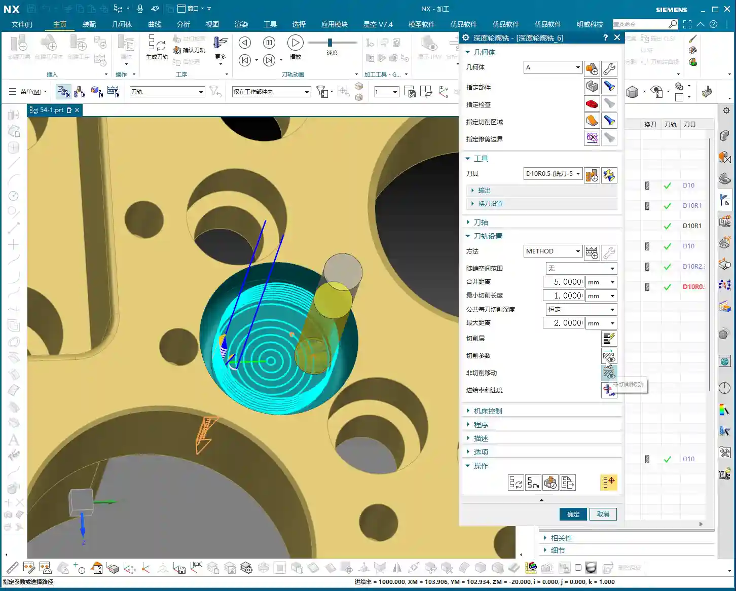
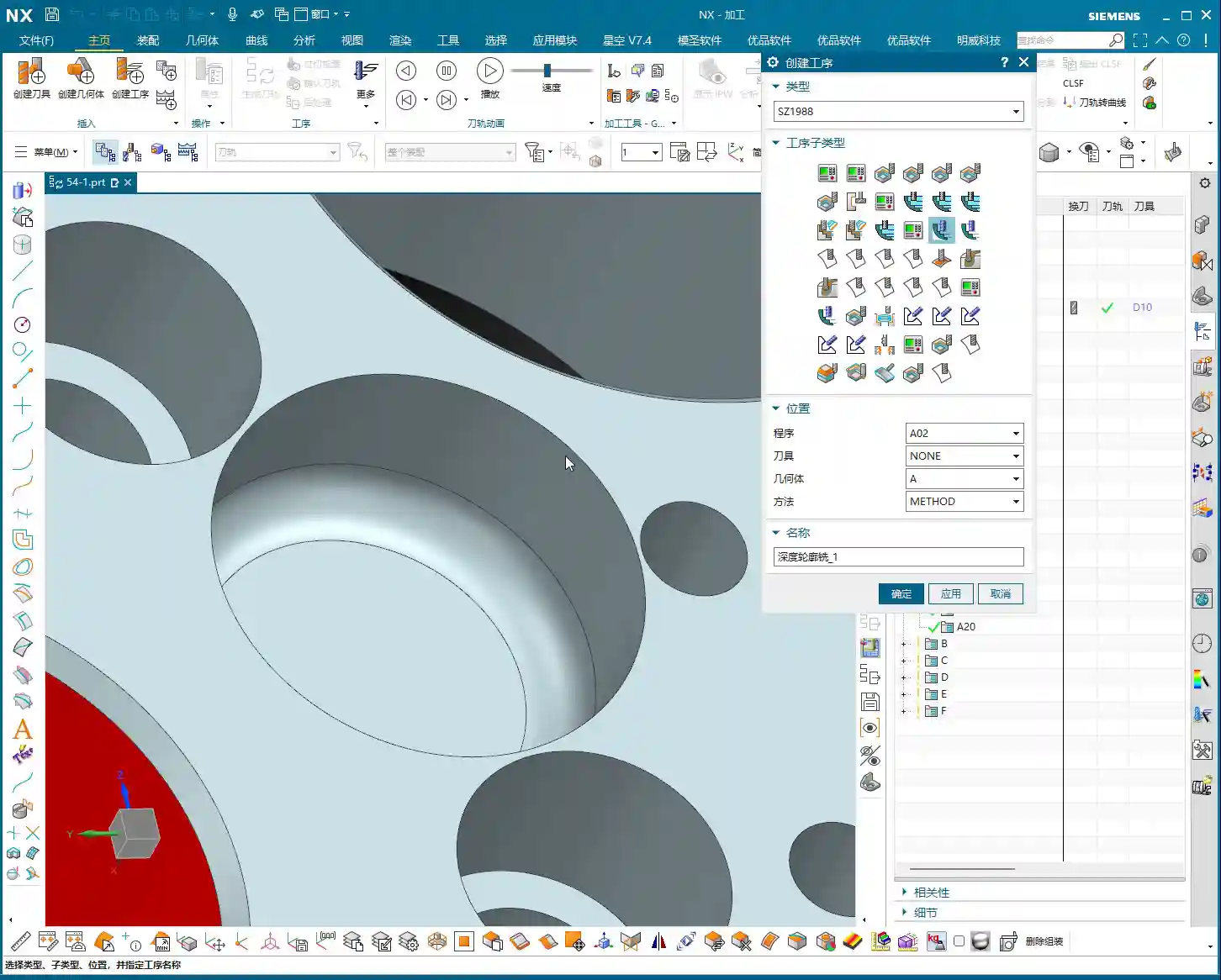
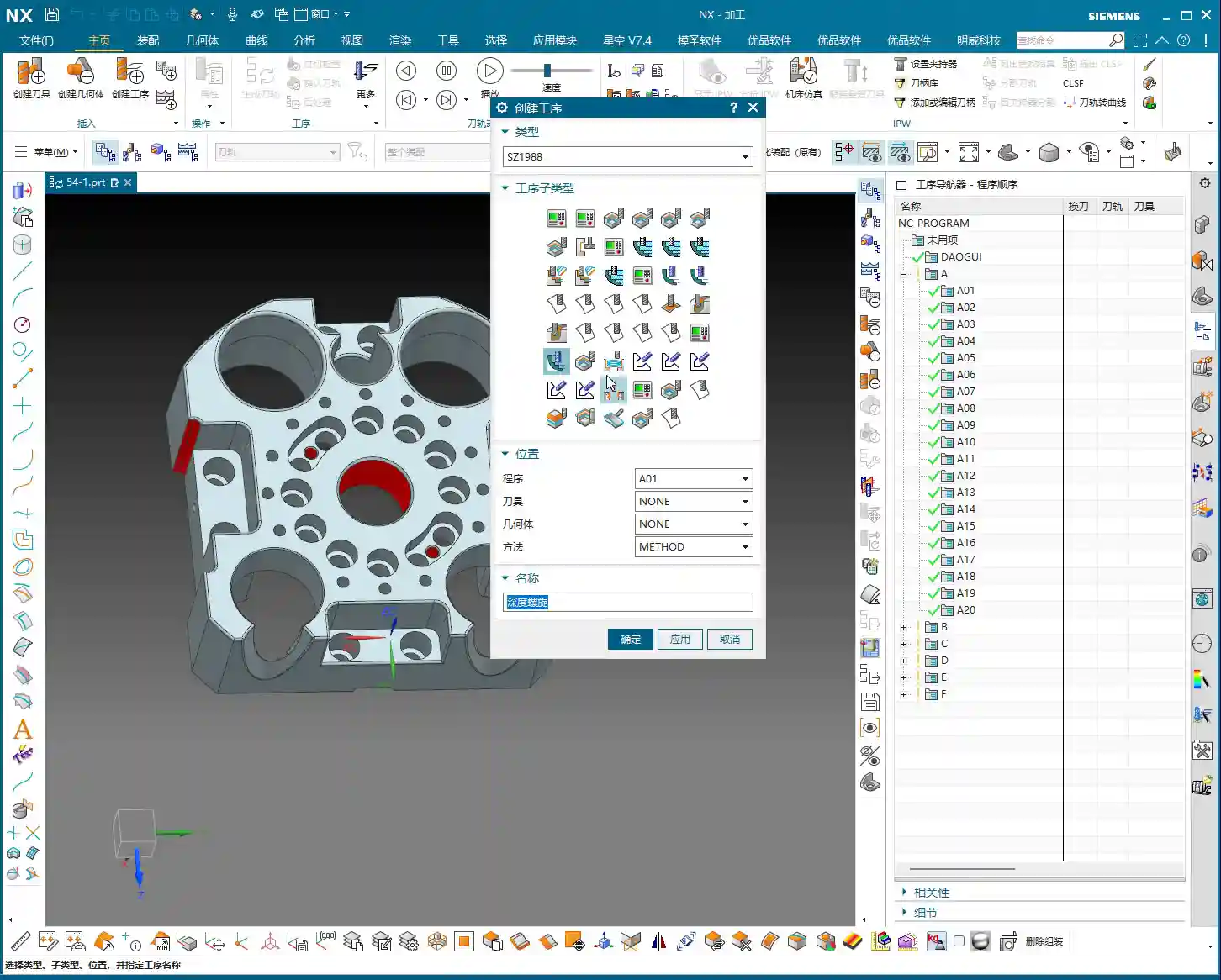
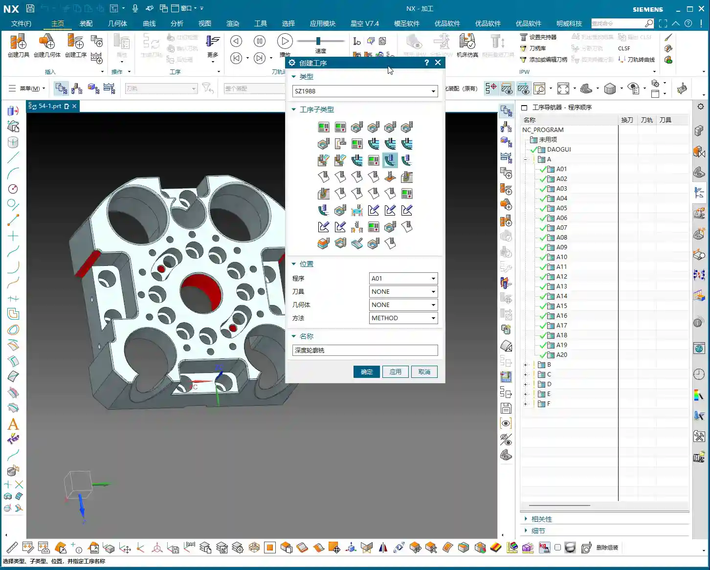
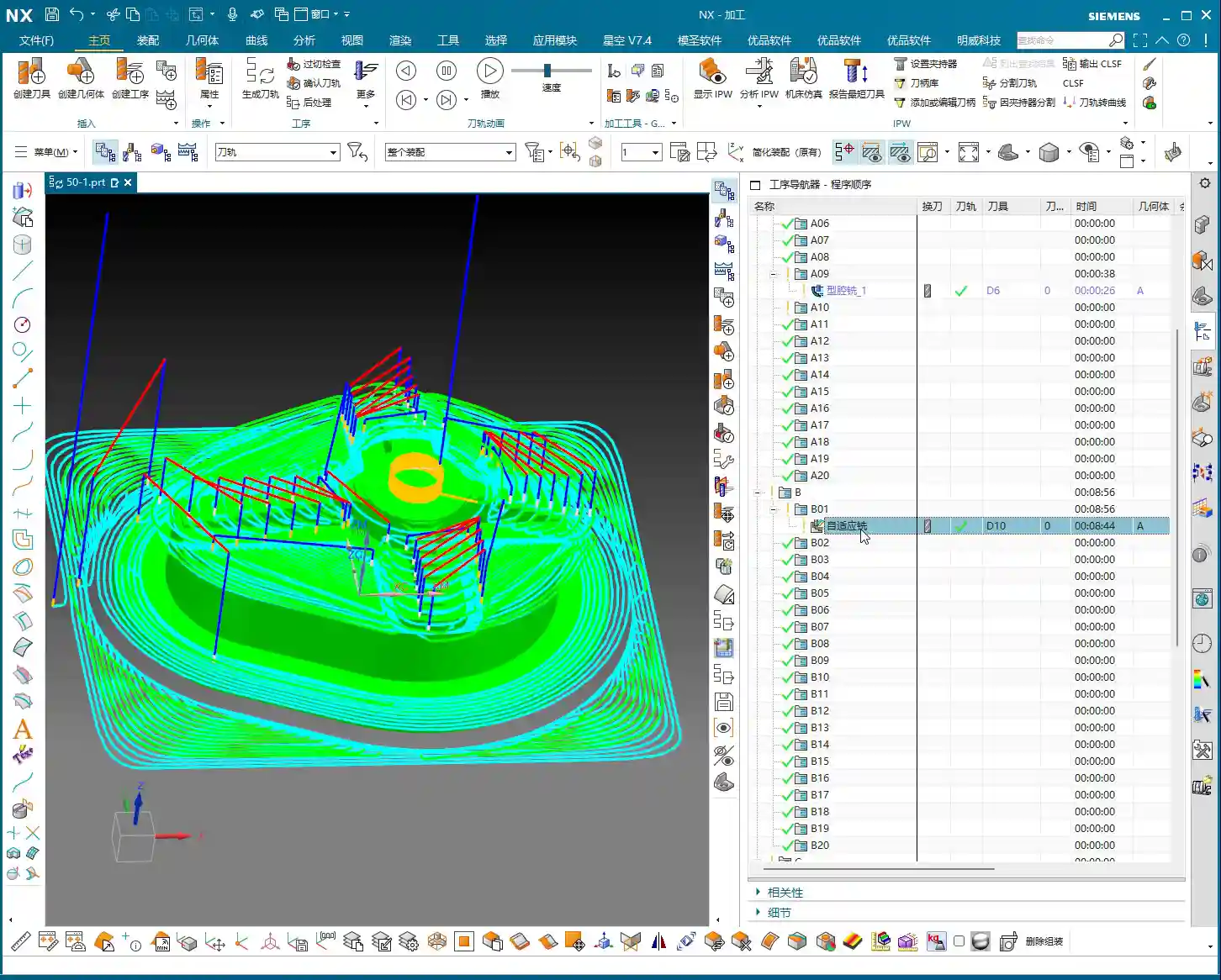
    NX Rest Milling Programming: Step One – Geometry and Tool Selection

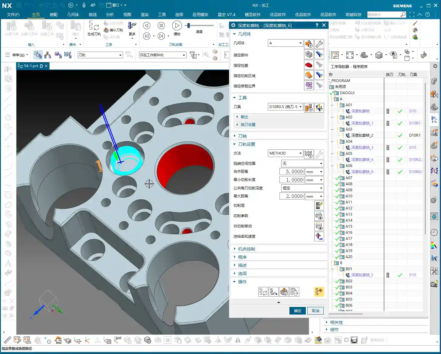
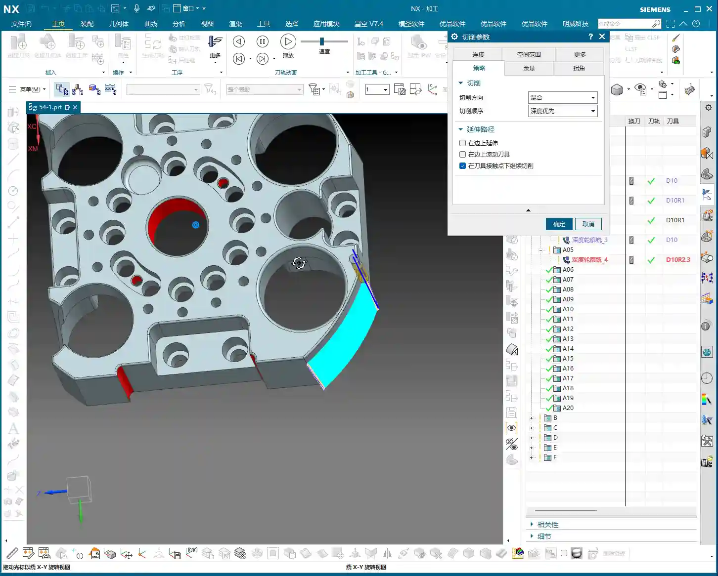
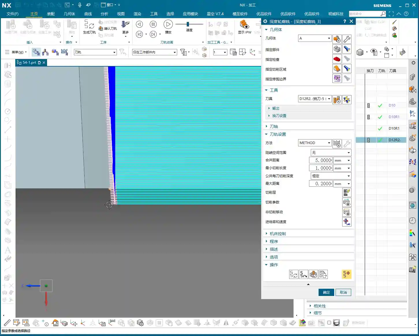
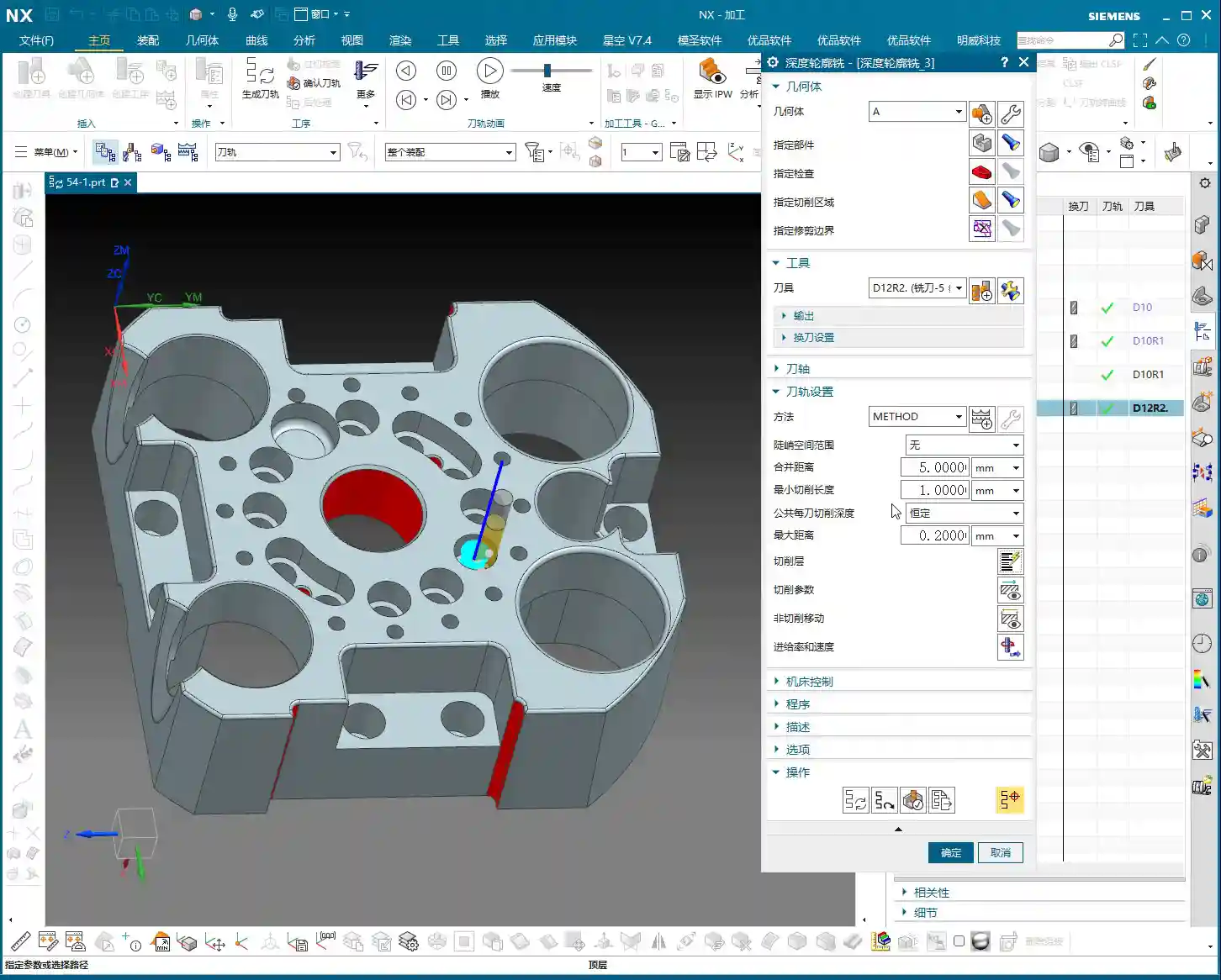
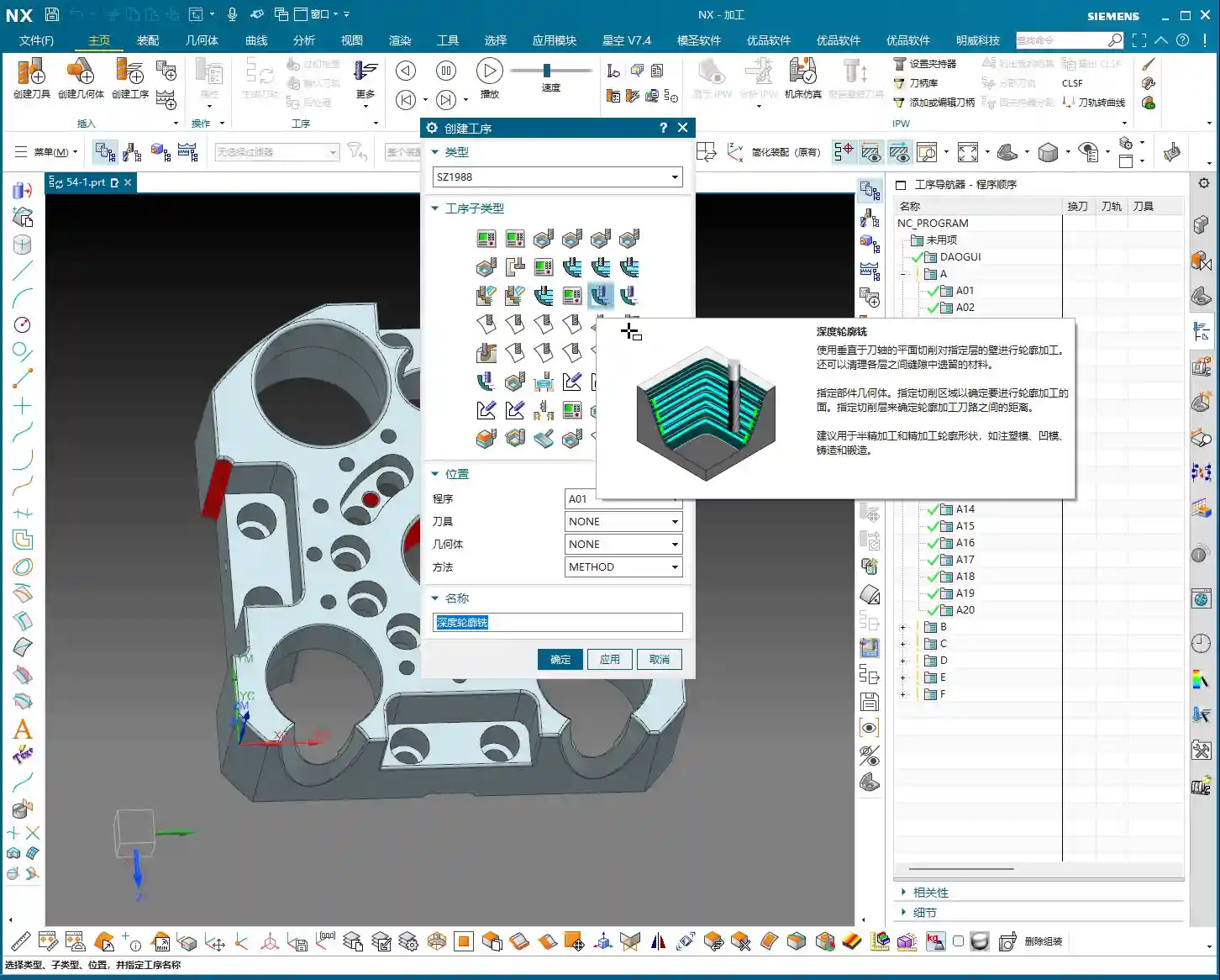
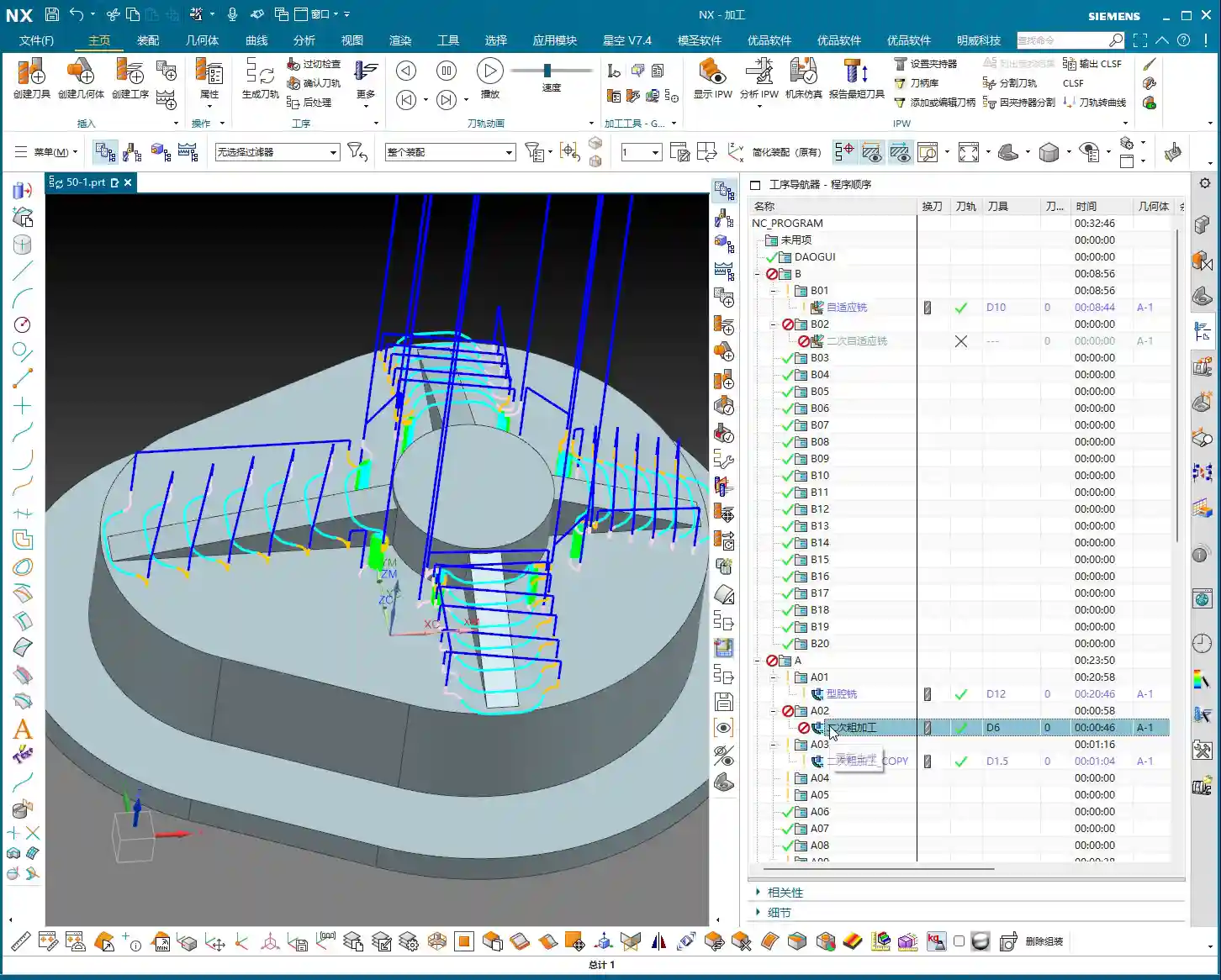
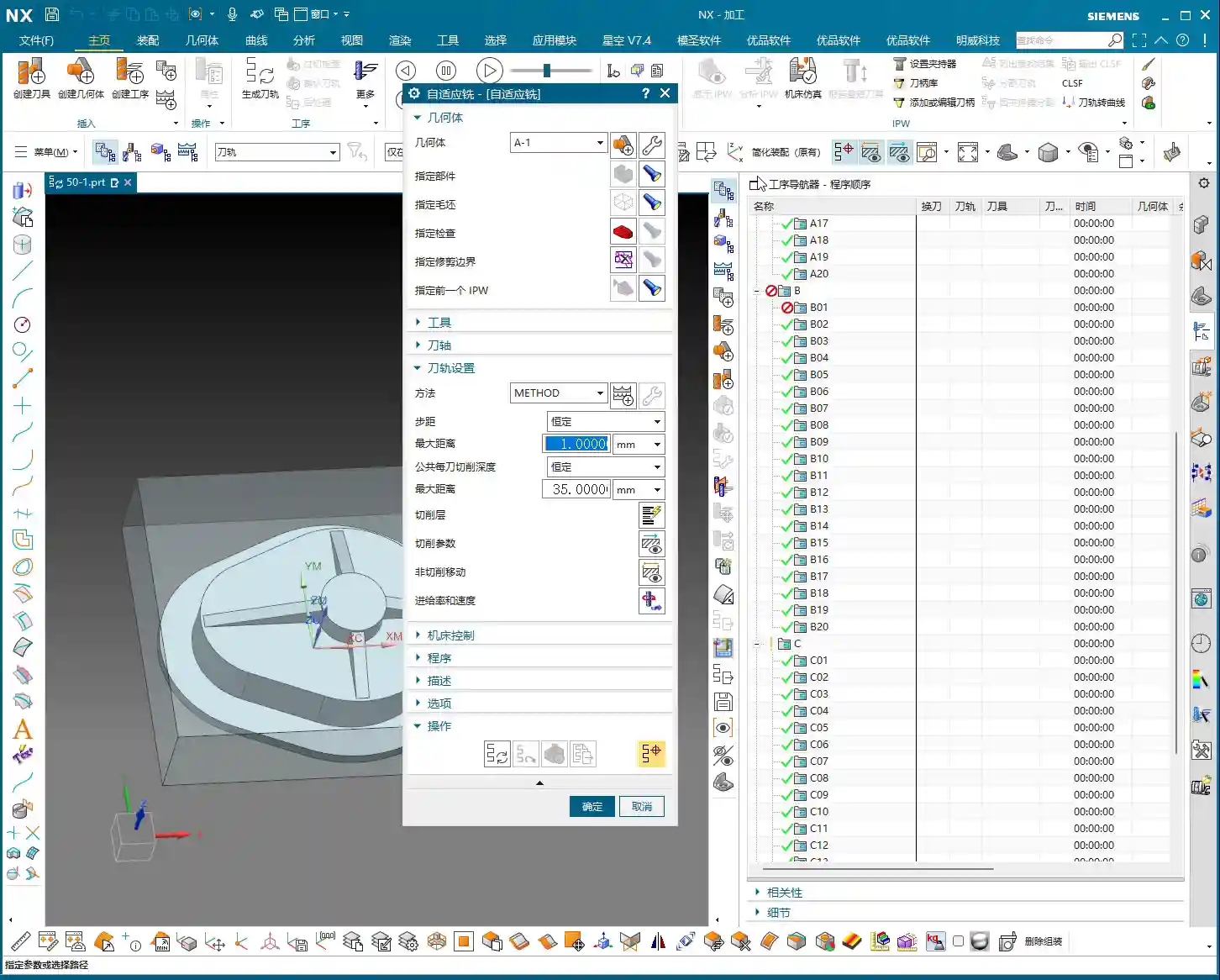
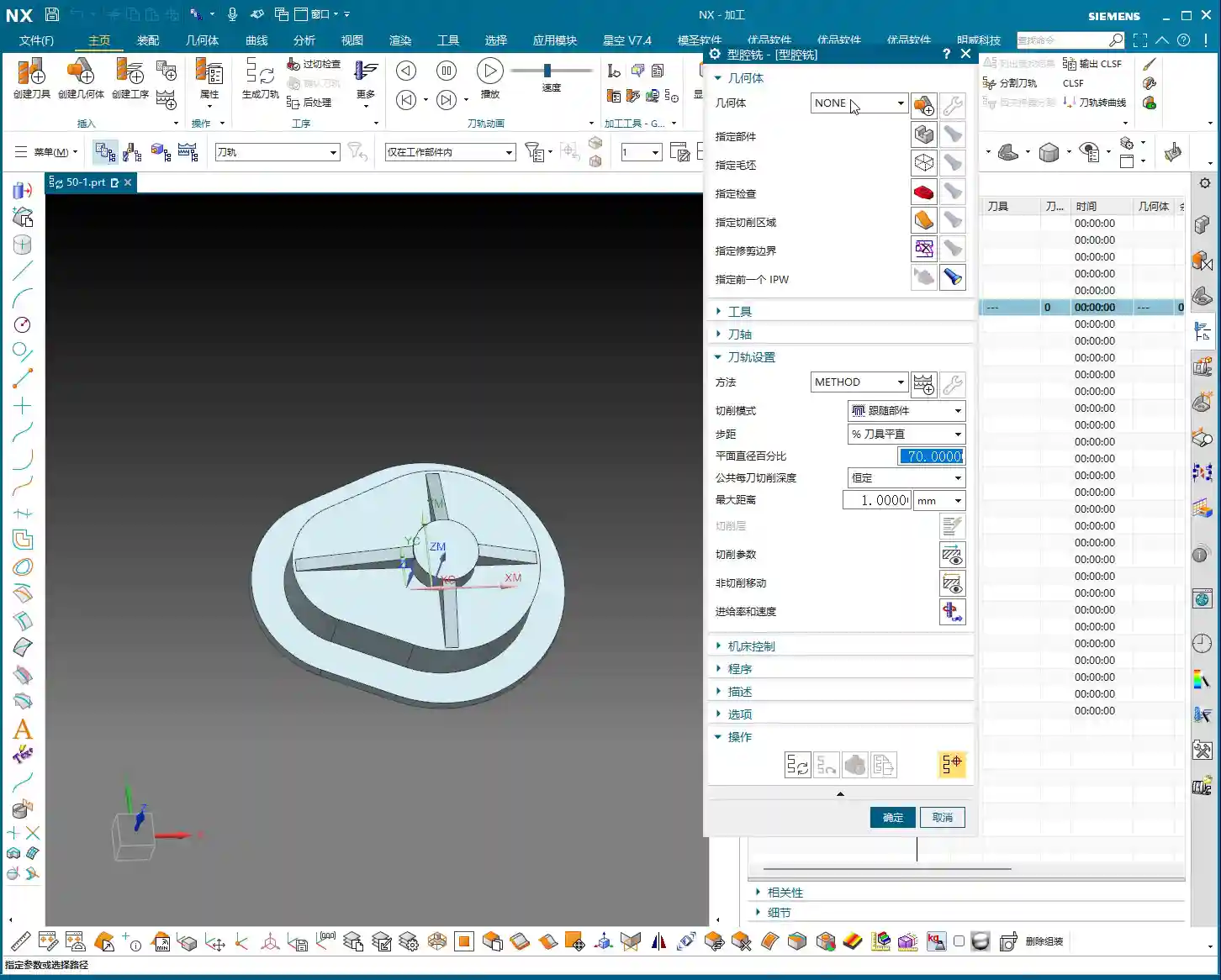
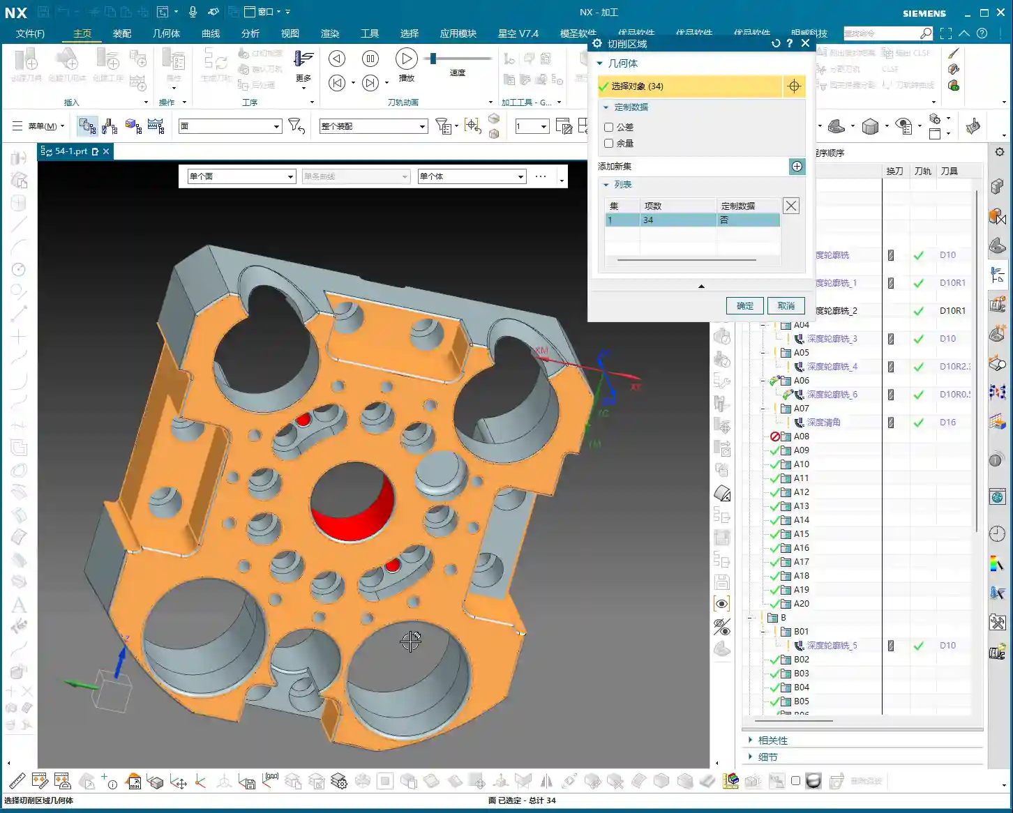
    In NX, find the “Deep Contour Rest Milling” function. Once you’re in, the first step is to select the geometry.

    Pay attention here; this is a major pitfall that textbooks might not cover in detail! When selecting the rest milling region, NEVER select ONLY the fillet face! You must select all faces around the fillet that need to be machined, including the bottom face. Why? Think about it: the tool is smart, but it’s not psychic. If you only give it an isolated fillet face, how will it know what size tool you used for roughing previously? How will it know the exact distribution of residual material? It can’t reference previous toolpaths, so it won’t be able to generate a rational, complete rest milling path. The result will be incomplete cleaning, messy toolpaths, or even a collision.

    Therefore, when selecting geometry, you need to provide the tool with “complete environmental information” so it can accurately determine where residual material exists and where rest milling is needed. Don’t be lazy; every face that needs to be selected must be included!

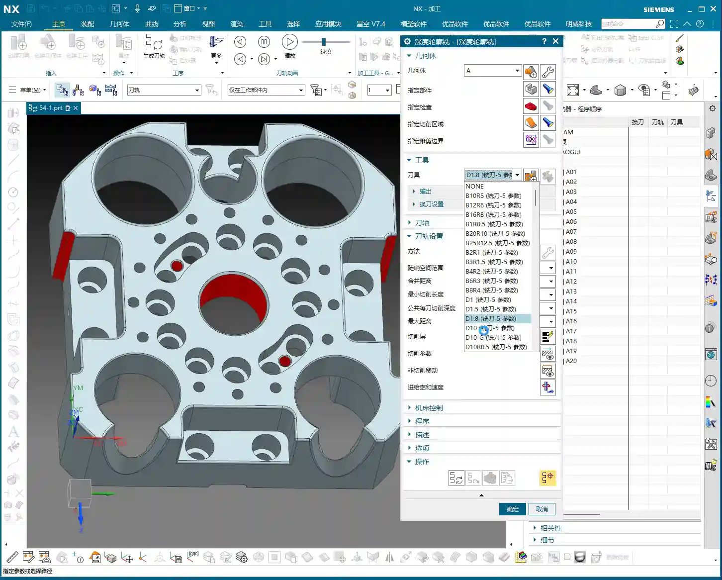
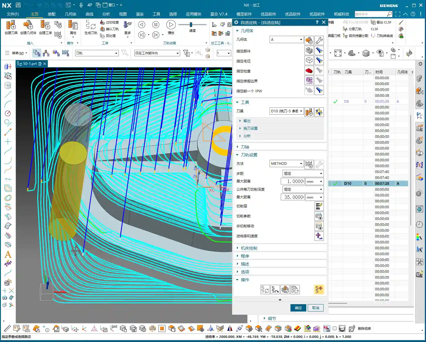
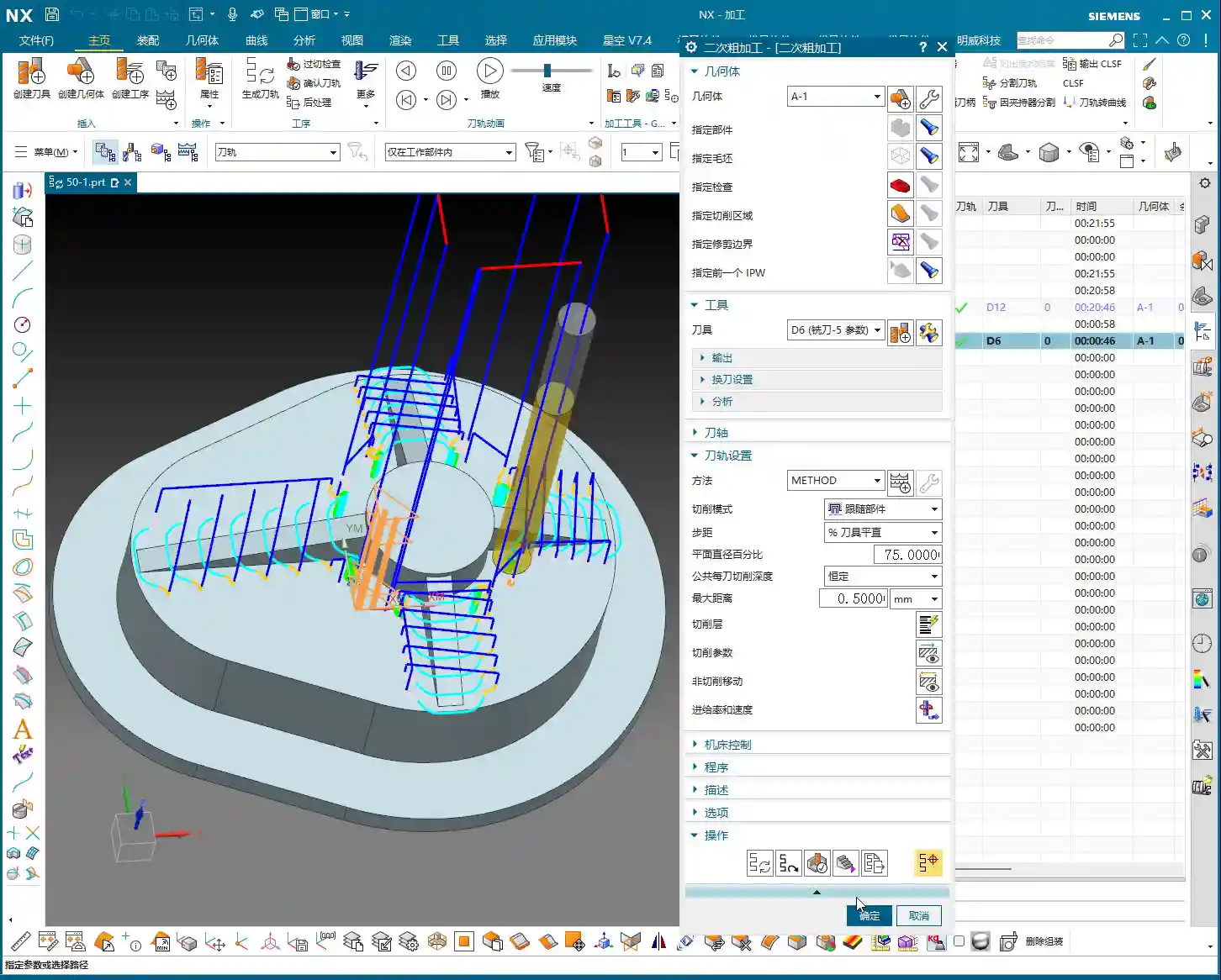
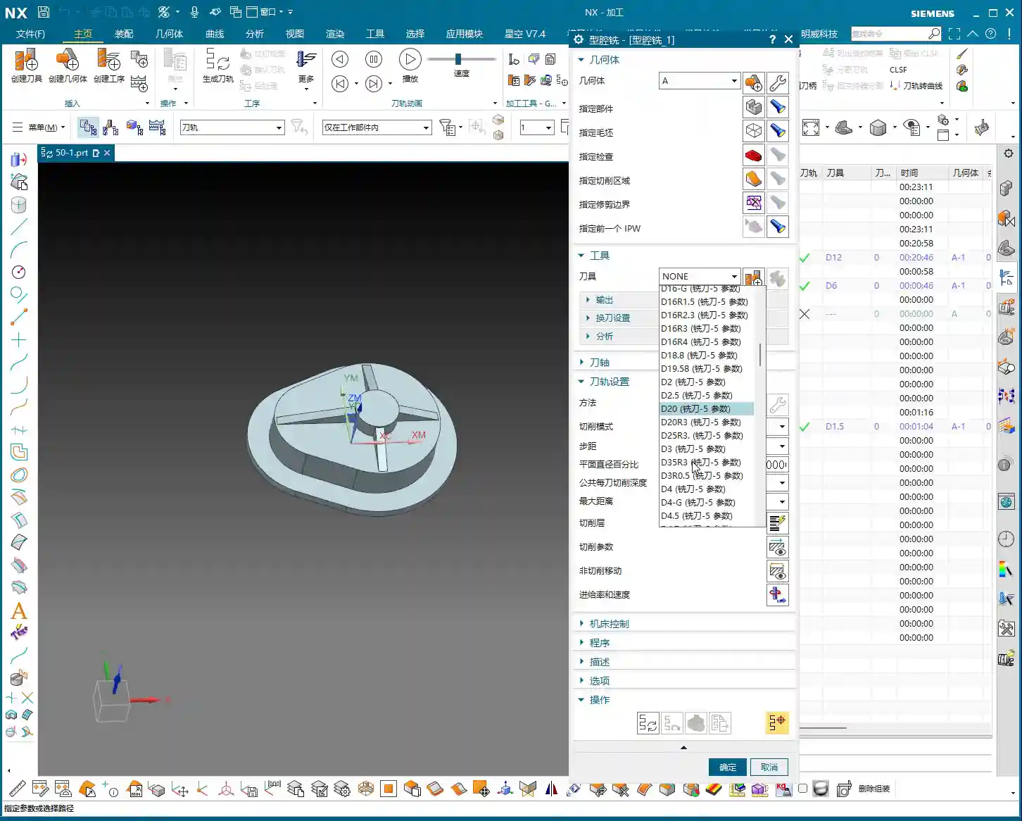
    Regarding tool selection, as we discussed, if you used a Ø32mm (approx. 1.26 inch) tool for roughing, you’ll need a smaller one for rest milling, such as a Ø16mm (approx. 0.63 inch) end mill. The principle is simple: smaller tools can access areas larger tools couldn’t reach.

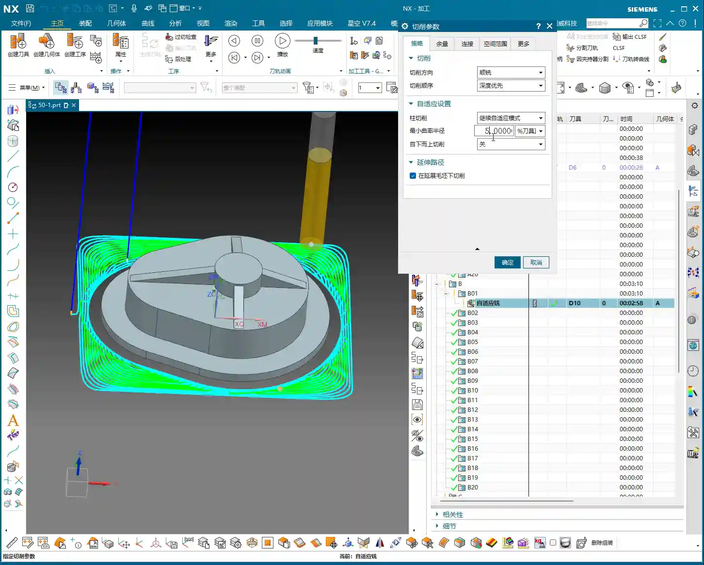
    Spatial Range: The Art of the Reference Tool

    The Core Secret of Rest Milling: The Reference Tool

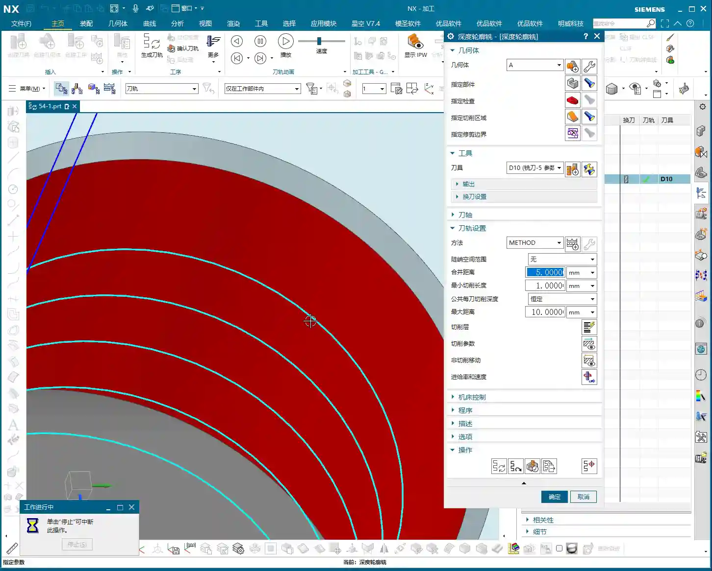
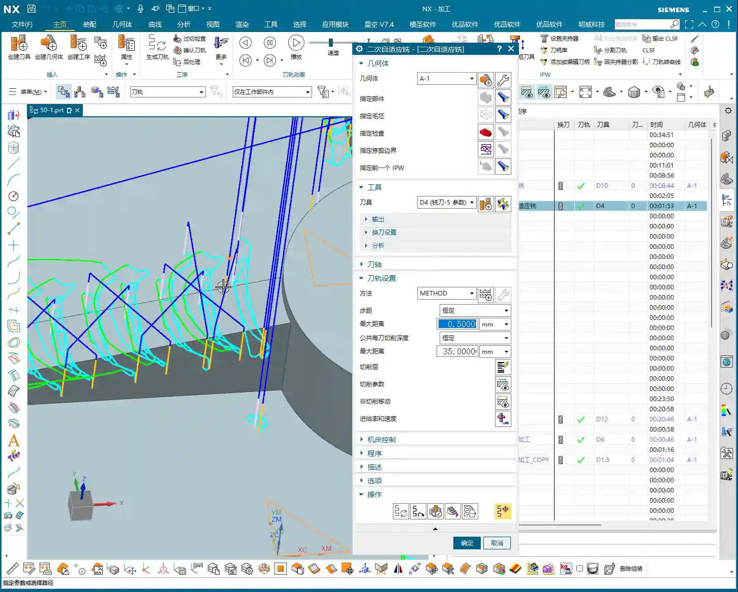
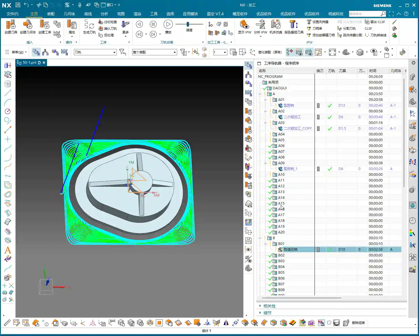
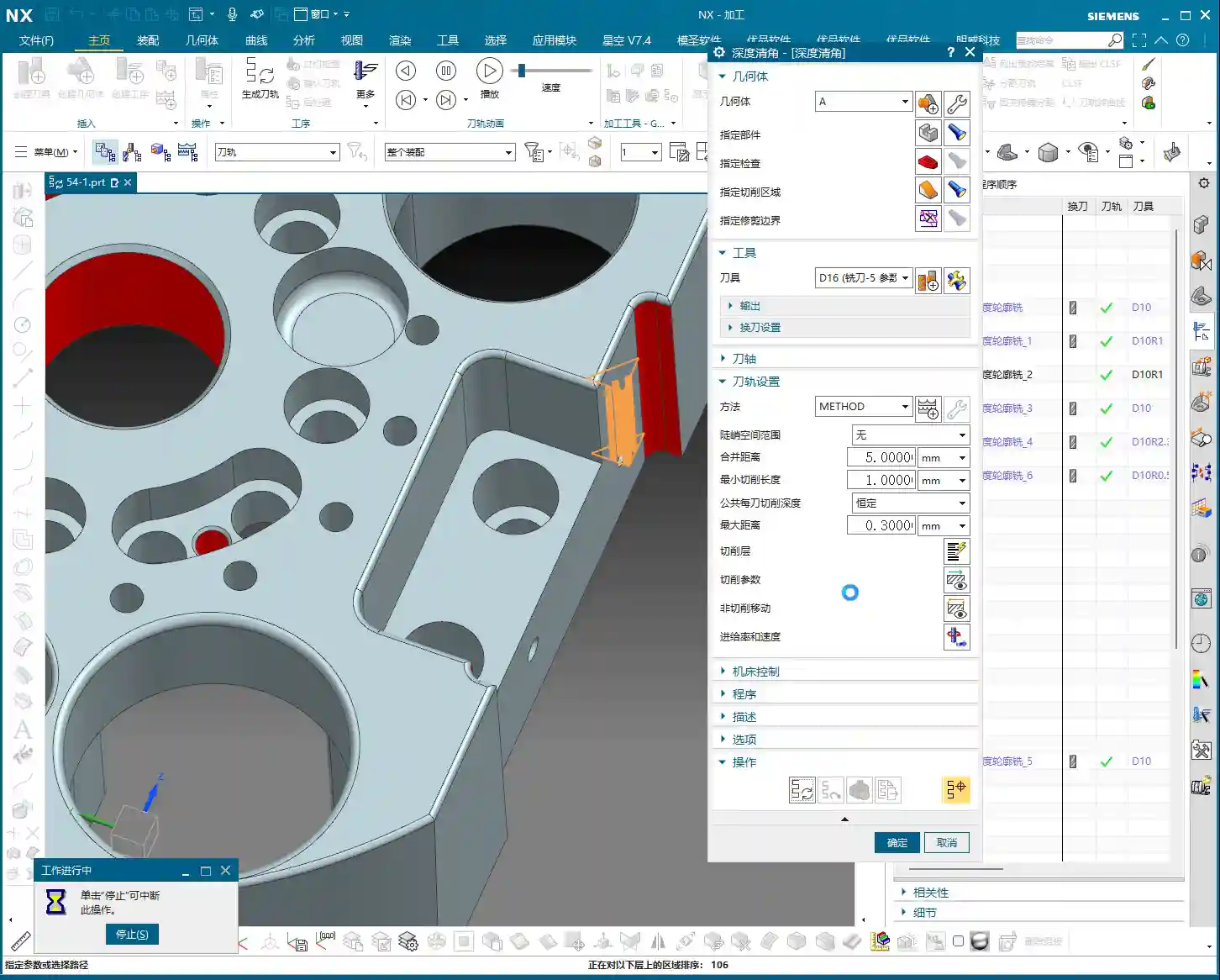
    Alright, everyone, the core of Rest Milling, and its sole critical difference from standard Deep Contour Milling, lies in the “Reference Tool” setting within “Spatial Range.” This is knowledge I, Master Wang, have refined over years, and you must grasp it thoroughly.

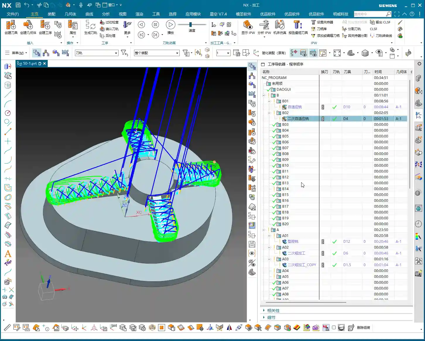
    You need to tell NX which tool you used for roughing previously. For example, in “Spatial Range,” enable the “Reference Tool” option, then select the Ø32mm (approx. 1.26 inch) tool you used for roughing. NX will automatically calculate the areas that tool couldn’t mill based on its profile – these are the residual material areas your current smaller tool needs to clear. Without this “reference,” Rest Milling is a meaningless term; it won’t know where to clean.

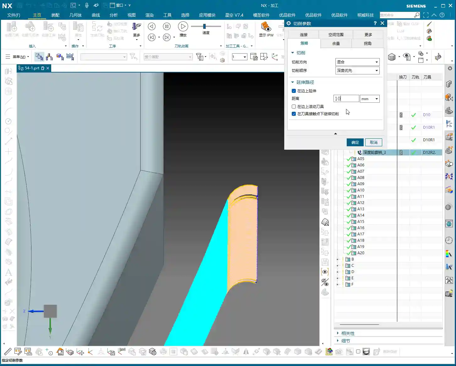
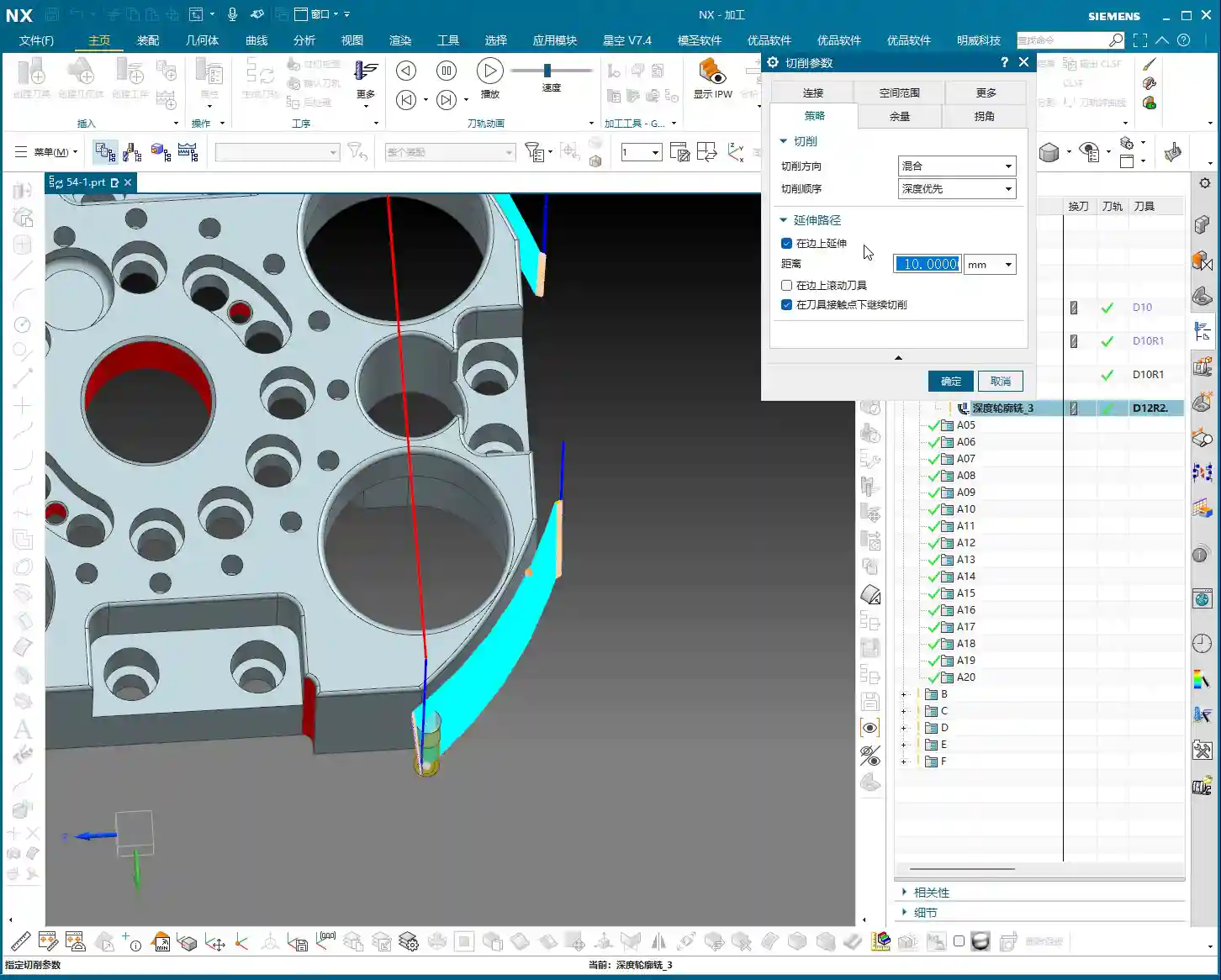
    Further down, there’s also “Cut Extension Distance” (or “Extension Distance”). This parameter allows your rest milling toolpath to extend slightly beyond the reference tool’s path. Why the need for extension? Because you might want the tool to cut a bit more to ensure all residual material is completely removed, preventing even the slightest “unmachined spots.” I usually set it to around 2mm (approx. 0.08 inch), but the exact value depends on the actual situation and material. You can also think of it as adding this distance to the reference tool’s diameter, simulating a slightly larger virtual tool (e.g., Ø34mm / approx. 1.34 inch), to calculate the range that needs to be cleared.

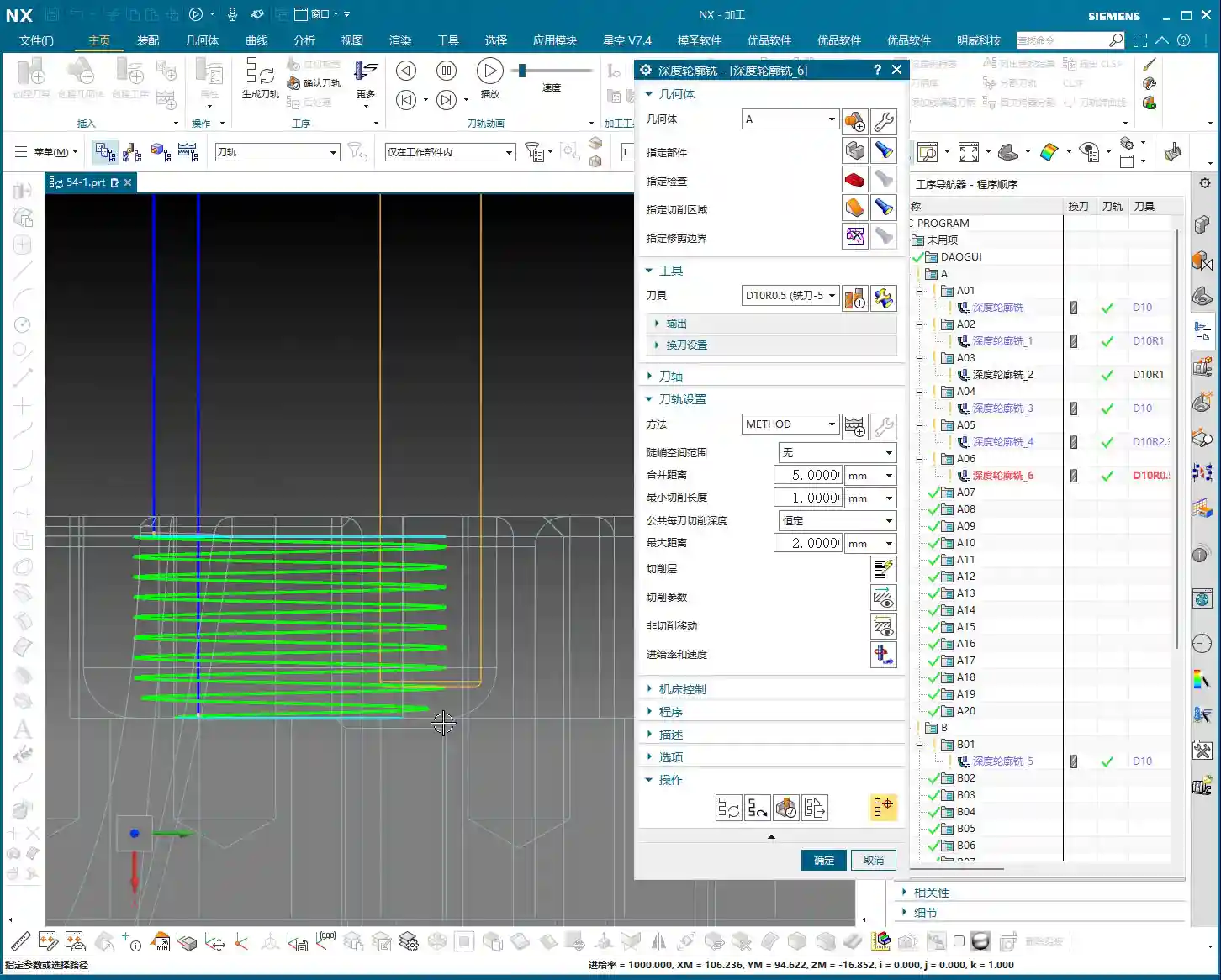
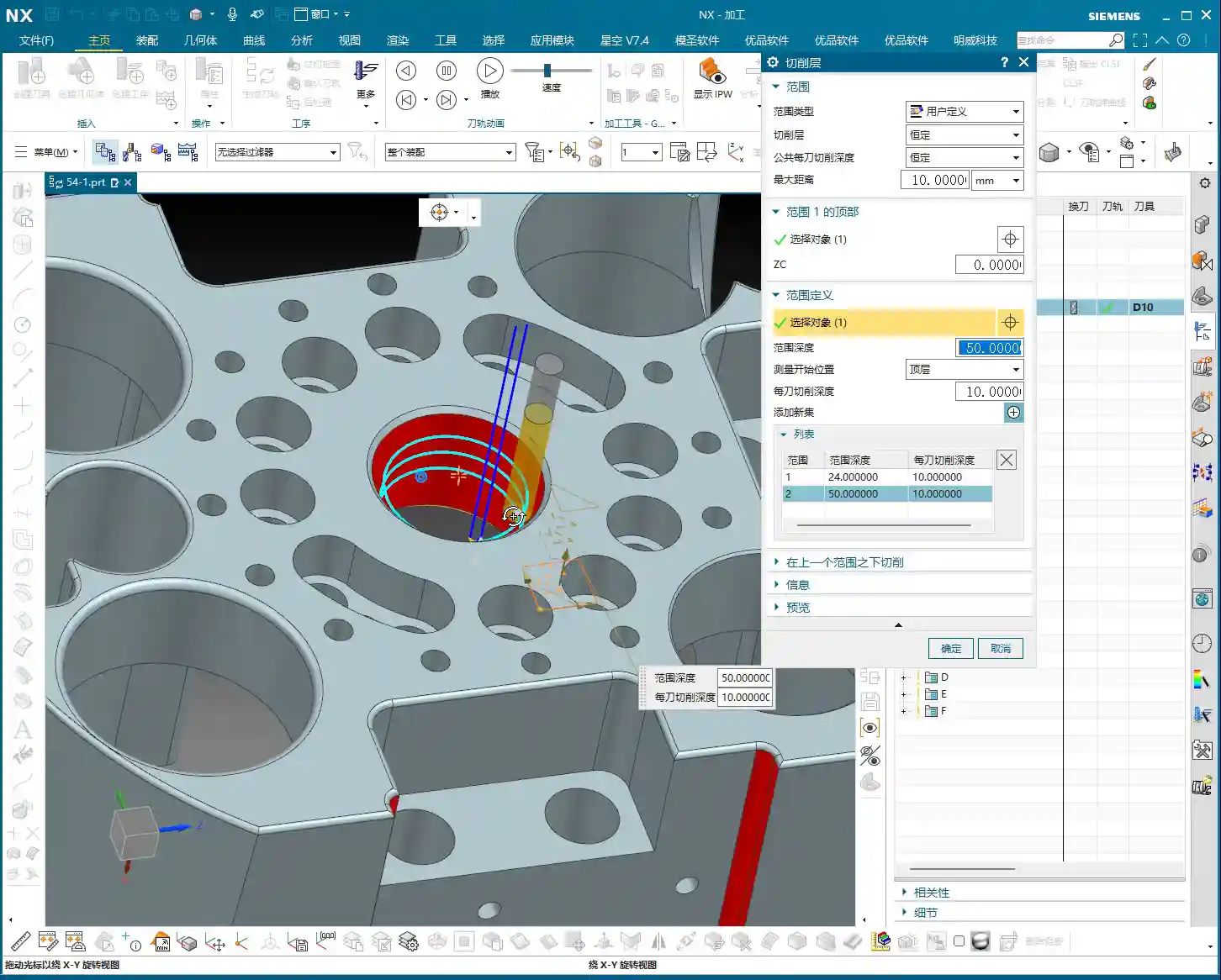
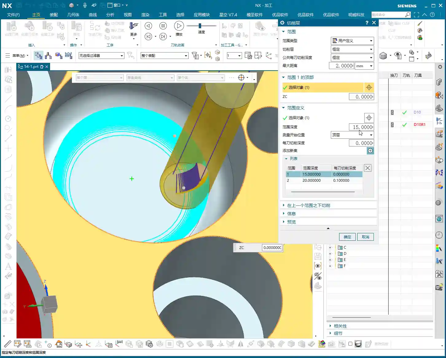
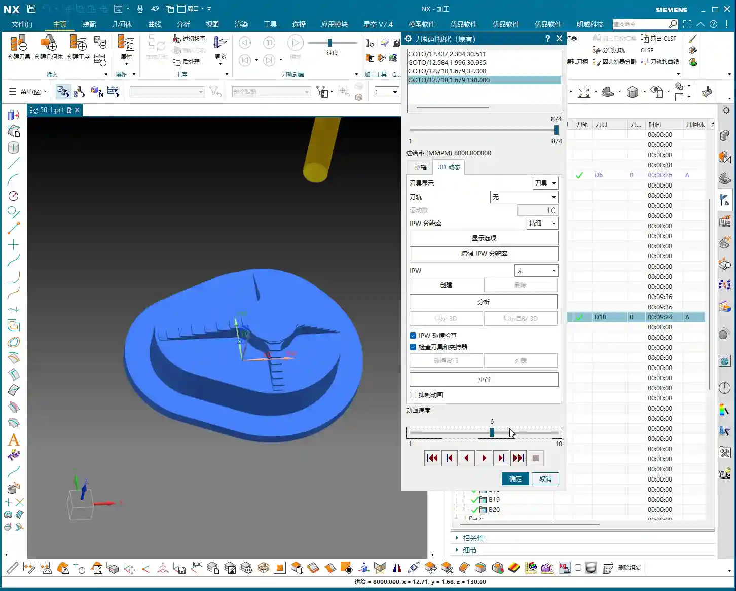
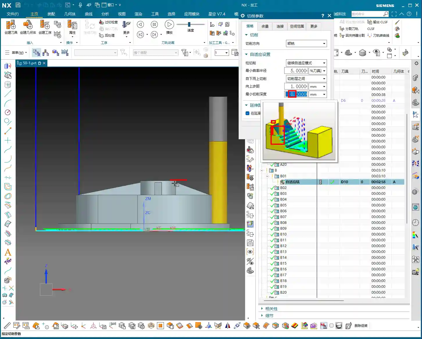
    Avoiding Pitfalls: Extended Application of Cutting Levels

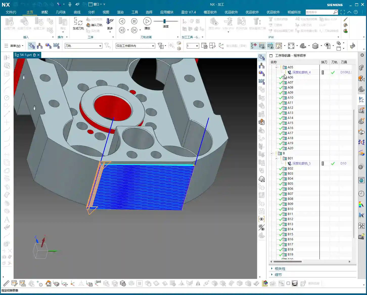
    Many beginners ask why their rest milling program always starts cutting from the middle. Shouldn’t it start from the top? This happens when the “Extension Distance” in “Cutting Levels” isn’t set correctly.

    If your rest milling depth is 2mm (approx. 0.08 inch), and you want the tool to start with a helical ramp down from the top, you need to set the “Extension Distance” to 1mm (approx. 0.04 inch) in the “Cutting Levels” settings. This way, the tool will start milling from the top of the workpiece, not the middle of the fillet, ensuring the completeness of the entire rest milling process. Don’t underestimate this 1mm; sometimes it can determine whether you’ll have a collision or the quality of your surface finish.

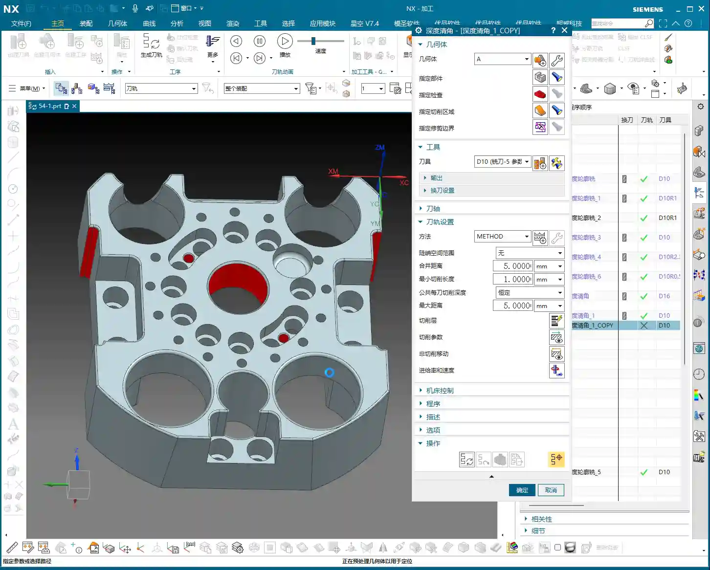
    One more thing, practical experience tells me that Deep Contour Rest Milling programs can be quite slow to calculate. If you set the Stepover too small, you’ll be waiting a while – enough time to grab a cup of tea, or even catch up on the neighborhood gossip. So, the Stepover setting must also balance efficiency; don’t just blindly aim for the smallest value.

    Smoothing Strategy: Enhancing Machining Quality

    Understanding “Smoothing”: More Than Just Fillets

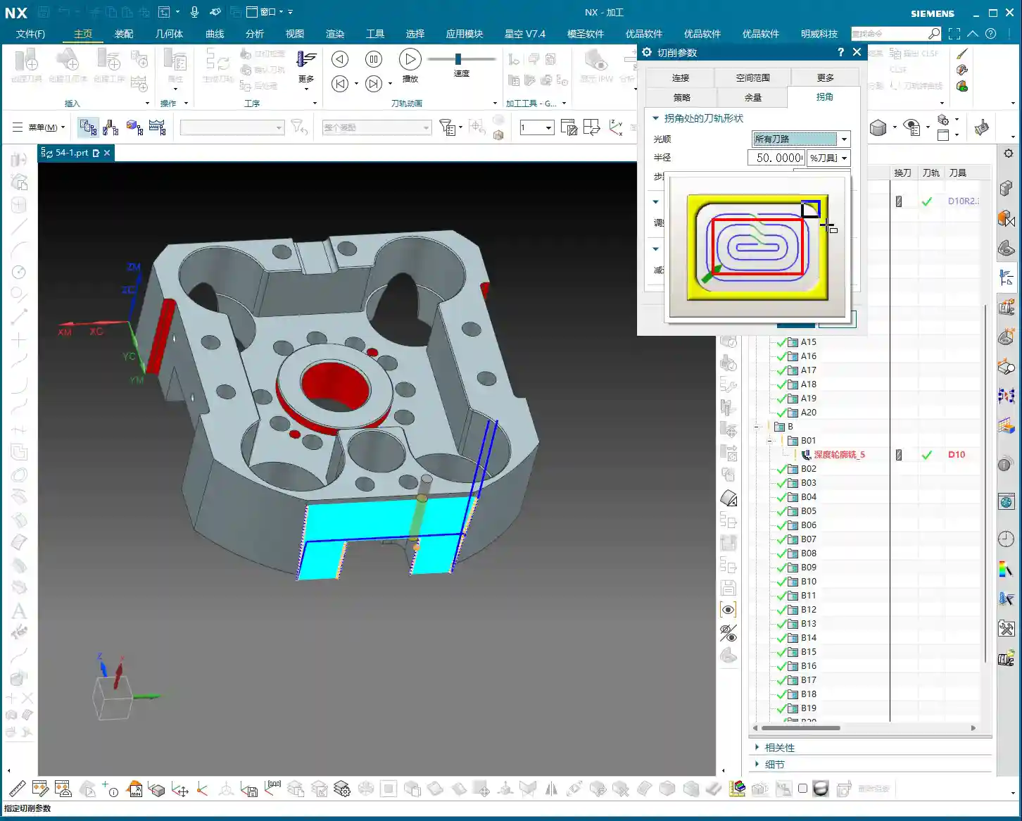
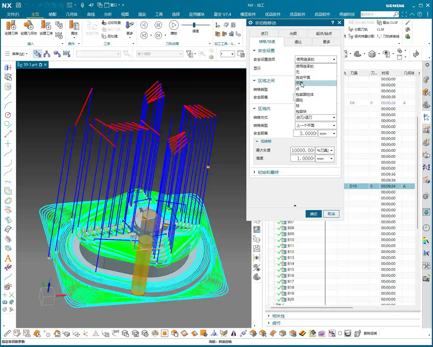
    In NX, this concept of “Smoothing” is a vast topic. It’s not a single idea. What we’re discussing today is “Smoothing” within “Non-Cutting Moves.” This “Smoothing” isn’t about the smoothness of a fillet or radius on your workpiece; it controls the stability of the tool during path connections, lead-in, lead-out, and the overall movement process.

    Think about it: if the tool suddenly accelerates, makes sharp turns, or has jerky lead-in/out moves during machining, it will leave tool marks on the workpiece surface, potentially cause machine chatter, and reduce tool life. Therefore, “Smoothing” in “Non-Cutting Moves” is designed to ensure the overall fluency of the toolpath, making the tool move as smoothly as silk, avoiding any “hesitation” or “jerking” feeling.

    Typically, I set this smoothing value to around 5mm (approx. 0.2 inch). This value both ensures a smooth toolpath and prevents the program from calculating too slowly. If this value is set too small, you’ll find that during simulation, the tool moves sluggishly, like a snail, and the tool motion will appear stiff and unnatural.

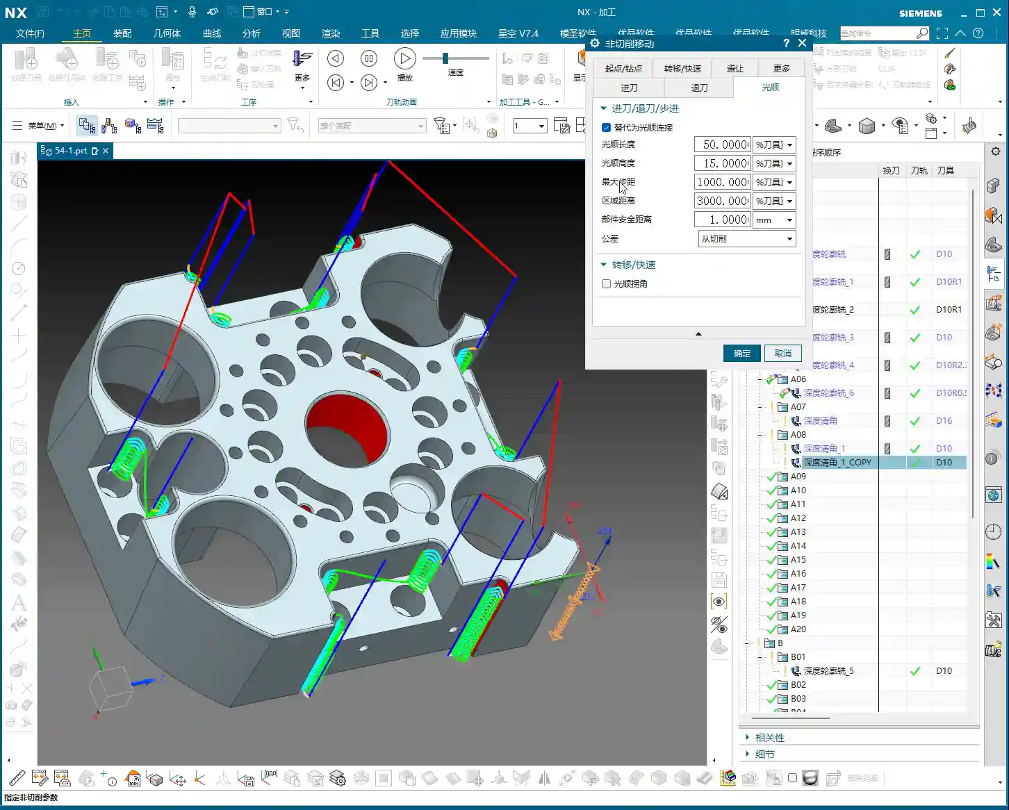
    Smoothing Parameters: The Secrets of Length and Height

    Within the smoothing parameters, there are two key components you need to understand:

    1. Smoothness Length: This refers to the horizontal extension distance of the tool from its current position to the next cutting point. It determines the degree of smoothness during transitions in the planar direction. In simple terms, it ensures that when the tool changes direction, it doesn’t turn abruptly but instead carves a smooth arc.
    2. Smoothness Height: This refers to the vertical transition height of the tool in the Z-axis direction. It ensures that when the tool performs Z-axis feed or retraction, there are no sudden axial changes, but rather a gentle transition.

    These two parameters are usually already optimized by experienced engineers in NX machining templates. For most situations, you can simply use the default template values; there’s no need to blindly modify them yourself. But as a qualified machinist, you must understand what each of them does. When issues arise, you’ll know where to start making adjustments.

    Summary: Your Pitfall Avoidance Guide

    As Master Wang, I’ve summarized these hard-hitting practical insights for you today. Every point is based on real-world experience, so commit them to memory!

    • Major Pitfall in Geometry Selection: When performing Deep Contour Rest Milling, CRITICAL: NEVER select ONLY the fillet face! You must select all machining faces around the fillet that need to be cleared, as well as the bottom face. This is to provide NX with “complete environmental information,” allowing it to understand where residual material is and what the previous tool’s machining range was. Otherwise, your rest milling toolpath will be messy, won’t clean properly, and may even cause a collision. Don’t be lazy; this is crucial!
    • Spatial Range Must Be Enabled: The core essence of the rest milling program lies in the “Reference Tool” setting within “Spatial Range.” This tells NX which tool you used for roughing previously, allowing it to intelligently calculate “uncut regions” that require rest milling. If this function isn’t enabled, rest milling is a meaningless term.
    • Fine-tuning Cut Extension Distance: The “Cut Extension Distance” parameter should be flexibly set based on the actual residual material left after roughing and the size of your rest milling tool. Experience dictates that it’s better to extend slightly more than necessary than to leave unmachined areas. However, don’t set it too large, or you’ll end up with air cuts.
    • Smoothing Settings Require Attention: “Smoothing” in “Non-Cutting Moves” is key to ensuring toolpath fluency and improving surface quality. It’s generally recommended to set it to around 5mm (approx. 0.2 inch). If set too small, you’ll find the program calculates like a snail, and simulations will be sluggish and choppy, affecting your ability to evaluate the toolpath.
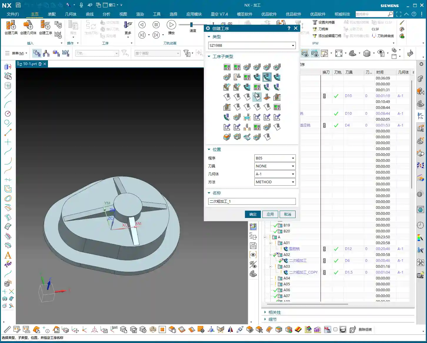
    • Simplify Complexity: For fillets or holes of different sizes and depths on a workpiece, it’s best to create multiple separate rest milling programs. One program should only clear regions with similar features (e.g., one program for all R5 corners, another for all R10 corners). The advantage of this approach is easier management, more efficient optimization, and simpler localization and debugging of issues. Don’t try to use one program for everything; that often leads to errors and wastes time.
    • Prioritize Templates, Understand the Principles: Most smoothing parameters and other settings in NX machining templates have already been optimized by experienced engineers. If there are no special requirements, using templates directly can save a lot of trouble. However, as an excellent machinist, you must understand the principles behind these parameters; this is your fundamental skill and your confidence to solve complex problems.

    👤 About the Author:
    The author is a veteran CNC machining professional with 15 years of industry experience, specializing in UG NX programming. This article is an original work representing personal practical insights.

    ⚠️ Copyright Notice: Unauthorized reproduction or distribution without prior communication is strictly prohibited.

  • Siemens NX Machining: Master Wang’s Essential Guide to Layer-to-Layer Transitions – Optimize Toolpat

    📝 Key Takeaways: Master Wang provides an in-depth analysis of Siemens NX’s four layer-to-layer transition methods. From the standard zigzag to high-risk direct plunge, and efficient ramp/helical entry to complex cross-ramp entry. He emphasizes practical priorities: Rapid Transfer (general purpose), Ramp/Helical (preferred for enclosed areas), and Direct Plunge (rarely used). Discover exclusive tips for optimizing toolpaths, extending tool life, and preventing thermal deformation, helping you boost accuracy and efficiency with essential CAM programming knowledge beyond textbooks! **

    Hello everyone, I’m Old Wang, but you can call me Master Wang. I’ve been grinding in the machining industry for fifteen years, smelled my share of cutting fluid and metal chips, and seen countless tricky problems. Today, we’re not going to talk about any abstract theories. Instead, let’s dive into some real-world stuff: layer-to-layer transition methods in Siemens NX. This is critical, directly impacting your tool life, machining efficiency, and part accuracy! Don’t underestimate these few options; there’s a lot more to them than meets the eye.

    What Are Layer-to-Layer Transitions?

    Listen up. “Layer-to-layer transition,” simply put, is how the tool moves to the next layer to continue machining after completing the current one. Does it plunge directly? Or does it helix down slowly? Siemens NX offers specific options for each method. When machining parts, especially deep pockets, cavities, or complex contoured parts, every new layer requires careful consideration of this transition move. Choose correctly, and you’ll boost efficiency; choose wrong, and you might face tool chipping, scrap parts, and wasted machine time.

    It’s like milling a hole – there are many ways to do it, but determining the safest and most efficient method relies on experience. Today, I’ll break down the four most commonly used methods in Siemens NX for you.

    Method One: Rapid Transfer (Standard Zigzag Move)

    Principle and Application

    In NX, this method is often referred to as “Use Transfer Method” or “Rapid Transfer.” The logic is straightforward: after the tool finishes machining the current layer, it will retract, move to the starting point of the next layer, and then plunge. This typically manifests as the tool making a “come over, go across, come over, lift, go across” motion, resembling a zigzag pattern.

    Master Wang’s Insights and Practical Tips

    • Pros: This is the most versatile and safest method. For most workpieces, especially those with irregular shapes or multiple islands, it effectively avoids obstacles, minimizes rubbing against previously machined surfaces, and reduces the risk of tool crashes. It features the shortest non-cutting distance, contributing to higher overall efficiency.
    • Applicable Scenarios: Almost all types of machining, particularly roughing and semi-finishing passes that require frequent tool retraction and repositioning. This is your go-to “fallback” option, suitable for both open and enclosed areas.
    • Master Wang’s Advice: Don’t just rely on software simulation—watch the cutting sparks! While it involves tool retraction, as long as the retraction height is set reasonably to clear obstacles, there’s no need to lift it excessively high and waste time. Always ensure sufficient safety clearance; better to have a bit more air cutting than a tool collision.

    Method Two: Direct Plunge into Part (Direct Plunge Style)

    Principle and Application

    This method is quite “aggressive.” It involves the tool plunging vertically directly from its current layer position to the starting point of the next layer. No retraction, no spiraling—just a straightforward plunge.

    Master Wang’s Insights and Practical Tips

    • Cons: Listen up, this is where you’re most likely to encounter heavy cutting loads! End mills are designed for peripheral cutting; their tip strength is weak. If you plunge directly, the axial force on the tool will be extremely high, easily leading to tool chipping, breakage, or even spindle damage. Furthermore, the tool tip’s cutting efficiency in the axial direction is very low, resulting in poor surface quality. Basically, this method should only be used as a last resort.
    • Applicable Scenarios: Theoretically, it can be used in open areas, but due to the immense impact on the tool, consider it only when machining very thin, very soft materials with excellent center-cutting tools, and when no other options are available. In enclosed areas, it is generally prohibited.
    • Master Wang’s Advice: When you see the words “direct plunge,” a red flag should go up in your head! As machinists, we must learn to treat our tools like gold. Avoid this method whenever possible. If you absolutely must use it, ensure the feed rate is very slow, the cutting load is minimal, and that the tool has ample through-tool or external coolant to prevent tool burning.

    Method Three: Ramp/Helical Entry into Part (Ramp/Helical Style)

    Principle and Application

    This method is far smarter than the second one. It allows the tool to enter the next layer gradually, following a defined ramp angle or helical path. In Siemens NX, there’s typically a parameter for the “Ramp Angle.”

    Master Wang’s Insights and Practical Tips

    • Pros: This method allows the tool to engage with its side flutes, distributing the cutting forces evenly, significantly reducing tool impact, and extending tool life. The resulting surface quality is also superior. Especially when the ramp angle is set to 0 degrees, it transforms into classic “Helical Milling,” where the tool rotates and descends like a drill from top to bottom, simultaneously performing side cutting. This achieves 3-axis simultaneous motion (X, Y, and Z axes moving concurrently).
    • Applicable Scenarios: Widely used for plunge cutting in enclosed areas, such as milling internal cavities or hole machining. Helical milling, in particular, is an excellent tool for roughing holes and an effective alternative to drilling, especially suitable for machining high-hardness materials like titanium alloys and high-temperature nickel-based alloys, as it significantly reduces tool wear and thermal deformation.
    • Master Wang’s Advice:

      • Choosing the Ramp Angle: A larger angle means faster plunging, but also higher cutting forces on the tool. Generally, based on material and tool conditions, 1-5 degrees is common. Small ramp angles, such as 1 or 2 degrees, result in minimal tool wear but a slightly longer entry time.
      • Helical Milling (Ramp Angle = 0): This is one of my most recommended plunging methods for enclosed areas. Ensure the helix radius is sufficient to prevent the tool center from rubbing against the hole wall, and also pay attention to the helical Z-axis feed rate, keeping it from being too aggressive.
      • Enclosed Area Restriction: Like the fourth method, this approach is only for enclosed areas. If your machining region is open, the software will either error out or generate an unsuitable toolpath.

    Method Four: Cross-Ramp into Part (Complex Ramp Style)

    Principle and Application

    This method also involves ramping into the part, but as it progresses, it performs a more complex “cross” or “S-shaped” plunging path, adapting to the part’s geometry. For certain specific geometries, it can achieve a smoother transition.

    Master Wang’s Insights and Practical Tips

    • Pros: In complex 3D surface machining, or when parts have unique sloped surfaces, this method can better adapt to the geometry, maintain stable cutting loads, and avoid sudden impacts.
    • Applicable Scenarios: Also suitable for finishing and semi-finishing passes in enclosed areas, especially where high demands are placed on surface quality and toolpath trajectory. For instance, in machining mold cavities, it might be used to minimize witness marks.
    • Master Wang’s Advice: This method is relatively less common, as its complexity can sometimes increase programming and calculation time. Typically, the ramp or helical entry of the third method will suffice. Only consider this method if you find that the third option doesn’t provide a satisfactory toolpath. And remember, it also only applies to enclosed areas.

      One crucial point: Whether using a ramp or helical entry, always check for collisions before plunging! Sometimes the simulated toolpath looks perfect, but when the machine runs, it might give you an unpleasant “surprise.”

    Summary: Collision Avoidance Guide

    Master Wang’s Practical Priorities and Pitfall Avoidance Experience

    Got it? These four layer-to-layer transition methods each have their specific uses, but they come with clear priorities and application conditions.

    1. First Choice: Rapid Transfer (Method One). Most versatile, applicable to both open and enclosed areas, high efficiency, low risk. This is your “all-rounder”.
    2. Second Choice: Ramp/Helical Entry into Part (Method Three, especially Helical Milling). For plunging in enclosed areas, this is the best option, as it maximizes tool protection and improves machining quality. Don’t forget, a ramp angle of 0 degrees means helical milling.
    3. Use with Caution: Cross-Ramp into Part (Method Four). Consider using it in specific situations; it also only applies to enclosed areas.
    4. Avoid or Use in Extreme Cases: Direct Plunge into Part (Method Two). Only if tool, material, and process conditions permit, and there are no other alternatives. Remember, direct plunging is the tool’s worst enemy!

    As machinists, we not only need to know how to use the software but also understand the process, know our tools, and comprehend the materials. Siemens NX’s features, no matter how powerful, are just tools. Ultimately, whether a part can be produced well, at a low cost, and with high efficiency still depends on the experience and judgment of us front-line experts.

    Don’t just stare at the toolpath trajectory on your computer screen; those are ideal conditions. At the machine, your eyes should watch the cutting sparks, your ears should listen to the cutting sound, and your nose should smell the cutting fumes. These “not-taught-in-textbooks” practical experiences are your true wealth.

    Let me emphasize again, Master Wang not only hand-machines high-precision parts but also knows how to make our industrial products stand out online. So, I’ll explain these core machining knowledge points in plain language, combining them with practical applications, so you can learn them and apply them effectively right away!

    Summary: Pitfall Avoidance Guide

    Finally, a few concluding remarks—all solid advice, remember them:

    • Prioritize smooth tool entry methods: Avoid tool impact and extend tool life.
    • For enclosed areas, frequently use ramp/helical entry: Good results, high efficiency.
    • For open areas, frequently use rapid transfer: Ensure safety and minimize air moves.
    • Material hardness and tool type dictate feed rate and spindle speed: Don’t generalize; apply flexibly.
    • Always verify programming: Ensure thorough simulation, and monitor the actual machining process throughout.
    • Don’t be afraid to make mistakes; be afraid not to try and learn from them: Every machining operation is a learning opportunity.

    Alright, that’s all for today. Next time, let’s talk about more hardcore knowledge!

    👤 About the Author:
    The author is a veteran CNC machining professional with 15 years of industry experience, specializing in UG NX programming. This article is an original work representing personal practical insights.

    ⚠️ Copyright Notice: Unauthorized reproduction or distribution without prior communication is strictly prohibited.

  • UG NX Practical Guide: In-Depth Explanation of Tool Rolling and Cut Below Tool Contact Point to Avoi

    📝 Key Takeaways: Master Wang provides a detailed explanation of UG NX toolpath optimization, focusing on “Tool Rolling” and “Cut Below Tool Contact Point.” This ensures clean edges and thorough corner cleanup at the bottom, eliminating residual material and avoiding air cuts. The tutorial offers an in-depth analysis of the practical advantages and disadvantages of “Cut Between Levels,” emphasizing that for complex parts, side walls and bottom surfaces should be machined separately to enhance both efficiency and quality. This guide distills fifteen years of hands-on experience, imparting techniques not found in textbooks, to help you truly master NX programming.

    Master Wang’s Talk: Advanced Siemens NX Machining Techniques

    Hello everyone, I’m Old Wang. I’ve been in this industry for fifteen years, and the experience I’ve gained from hands-on work in the shop floor—that’s something you won’t learn from textbooks. Today, we’re not going to talk about abstract theories; we’re diving straight into practical insights. Let’s discuss some easily overlooked parameters in Siemens NX programming that have a huge impact on machining quality and efficiency.

    Especially for complex surfaces and precision parts, these details determine whether you get it “right the first time” or have to “rework and modify the mold.” Listen up, this is all hard-earned, valuable experience.

    I. Tool Rolling: Making Your Toolpaths More “Smooth”

    In Siemens NX “Z-level Profile Milling” or “Depth Contour Milling” operations, we often encounter an option called “Roll Tool on part edges”. Many novices might think this is an unimportant option, or simply don’t know what it does. But Master Wang tells you, if you use this correctly, it can significantly improve the edge quality of your part.

    What is Tool Rolling?

    Let’s use an analogy. With a normal toolpath, when approaching a right angle or sharp corner, the tool’s center path directly follows the model’s edge, and the tool side “cuts straight through.” However, if you select “Roll Tool on part edges”, the software automatically adjusts the tool’s tilt angle, allowing the tool to “roll” smoothly over these edges. This is like running your hand over a sharp edge: is it more painful to slide straight across, or more comfortable to roll over it slightly tilted? Rolling over it is definitely smoother.

    Practical Application and Key Pitfalls to Avoid

    • Purpose: Primarily to improve the surface quality of part edges, reduce burrs, and prevent tool impact. This effect is especially noticeable when machining parts with chamfers or fillets. It helps distribute cutting forces more evenly and extends tool life.
    • Effect: You’ll notice the toolpath will “turn slightly” when approaching an edge, as if to “smooth out that little corner”. Don’t just stare at the simulation in the software; those are theoretical paths. On the actual machine, you need to observe the cutting sparks and listen to the cutting sound to determine if the tool is running smoothly and engaging properly.
    • When to Use: Generally, if you’re only performing roughing or if edge finish requirements are not high, you typically don’t need to select this option. The extra “rolling” motion might slightly increase machining time. However, for finishing passes, especially for edge refinement on high-precision parts such as mold cavities or turbine blades, this option becomes very important.

    II. Cut Below Tool Contact Point: The Secret to Clearing Residual Material

    This option in Siemens NX is called “Cut below tool contact point”. Often, when machining a curved surface with a ball end mill or a radius tool, theoretically the tool reaches the bottom, but in reality, a small amount of residual material might still be left along the bottom edge. This is due to the tool’s geometry.

    Core Principle: True Contact Between Tool and Workpiece

    Imagine you’re using a ball end mill to machine a deep groove. When the theoretical tool contact point (typically the tool tip or the lowest point of the radius) reaches the bottom edge of the groove, if “Cut below tool contact point” is not selected, the software will consider that spot “machined to depth,” and the toolpath will stop extending downwards. However, due to the spherical part of the ball end mill, a small amount of unmachined material might still be hidden beneath the edge. The software won’t continue cutting further down because it believes there’s nothing left for the tool to contact on that main surface.

    However, when you select this option, Siemens NX intelligently determines that even if the theoretical tool contact point has reached the boundary, as long as the tool’s “actual cutting portion (e.g., the spherical part of a ball end mill)” can still engage the model, it will continue extending the cut downwards until the residual material in that corner is completely removed. As illustrated in the diagram, one toolpath will extend further down than the other.

    An Essential Option for Precision Machining

    • Function: Ensures that residual material at the intersection of vertical walls and bottom surfaces is completely removed, resulting in sharper, more precise edges. This is crucial for parts requiring strict dimensions and surface quality.
    • Misconception: Some might think this could lead to overcutting, but that’s not the case. Siemens NX considers the tool’s true geometry during calculations and won’t cut downwards indefinitely. It only machines material that “theoretically should be cut, but might be missed due to tool geometry limitations.”
    • Efficiency and Quality: If you don’t select this option, you’ll likely need a second tool or subsequent manual finishing to remove these residual materials, which undoubtedly increases cost and time. Especially when machining deep pockets, ribs, or performing corner cleanup on molds, this option can save you a lot of trouble.

    III. Cut Between Levels: Optimizing Paths to Improve Surface Finish

    In Siemens NX machining operations, especially in some 3D milling strategies like “Depth Contour Profile” or “Z-level Profile Milling”, you might see the parameter “Cut between levels”. This function is primarily designed to add extra toolpaths between existing cutting levels to achieve a better surface finish or more uniform machining allowance.

    Principle and Application Scenarios

    As its name suggests, Cut Between Levels inserts additional intermediate toolpaths between our established normal cutting levels. It doesn’t simply increase the Depth of Cut (DOC), but rather, builds upon existing toolpaths by adjusting the stepover to increase the cutting density on angled and curved surfaces. The result is a reduction in the “stair-stepping” marks left by the previous tool on these surfaces, leading to a smoother surface transition.

    • Advantages: For finishing passes on parts requiring high surface finish, Cut Between Levels can significantly improve results. It can effectively reduce surface roughness without substantially increasing overall machining time.
    • Disadvantages (to Note): If misused, especially on complex open geometries, it might generate redundant toolpaths or even “imperfect” toolpaths, which can actually decrease efficiency.

    Master Wang’s Practical Experience: Separate Machining is More Reliable

    Although Siemens NX provides some conveniences, allowing you to process both side walls and bottom surfaces simultaneously in a single operation using Cut Between Levels—for example, in “Depth Contour Milling”, when you select it, it will attempt to finish the side walls and then finish the bottom surface as well. However, having worked in this field for so many years, my advice to you is: unless it’s a very simple part, always try to machine the side walls and bottom surfaces in separate finishing passes!

    Why?

    1. Control: Separate machining allows for more precise control over the machining parameters for each area. The cutting conditions, tool selection, and stock allowance strategies for bottom surfaces and side walls can differ significantly.
    2. Machining Stability: For “open geometries,” forcing a single toolpath to simultaneously finish side walls and bottom surfaces can very likely lead to “less-than-perfect” toolpaths, or even issues like chatter and overcutting.
    3. Not for Novices: For beginners just learning Siemens NX, I do not recommend using “Cut Between Levels” to simultaneously process both side walls and bottom surfaces right from the start. Stick to using “Planar Milling” for finishing bottom surfaces and “Depth Contour Milling” for finishing side walls. Operate separately, step by step, and build a strong foundation. Once you gain sufficient experience, then consider these advanced combined techniques.

    Summary: A Guide to Avoiding Pitfalls

    • Tool Rolling: Consider for finishing passes on edges; generally not needed for roughing. Always observe the actual cutting effect.
    • Cut Below Tool Contact Point: Addresses residual material at the intersection of vertical walls and bottom surfaces, ensuring thorough corner cleanup, improving precision, and reducing subsequent rework.
    • Cut Between Levels: Improves surface finish on angled and curved surfaces. However, for complex parts, when performing finishing passes on side walls and bottom surfaces, try to machine them separately. Don’t sacrifice long-term reliability for short-term convenience.

    Remember, textbooks teach theory, but the shop floor hones experience. Observe more, ask more questions, and practice more to truly become a skilled machining master!

    👤 About the Author:
    The author is a veteran CNC machining professional with 15 years of industry experience, specializing in UG NX programming. This article is an original work representing personal practical insights.

    ⚠️ Copyright Notice: Unauthorized reproduction or distribution without prior communication is strictly prohibited.

  • Siemens NX Deep Contour Milling Practical Guide: Optimized Cutting Layers & Boundary Extension, Unve

    📝 Key Takeaways:

    Deep Contour Milling: Practical Insights into Cutting Layers and Boundary Extension

    Alright, listen up, young…

    Alright, listen up, young machinists! Today, Master Wang is going to share some critical, practical knowledge about deep contour milling—the kind of stuff they don’t teach you in textbooks, but that you absolutely need on the shop floor. Specifically, we’ll talk about cutting layer control and the boundary extension function. Use them wisely, and you’ll boost efficiency; mess them up, and you’ll be scrapping parts, wasting time, and burning through tools. Don’t just rely on software simulations; look at the cutting sparks and the chip color—that’s where the real skill lies!

    I. Cutting Layer Control in Deep Contour Milling

    Deep contour milling, as the name suggests, is primarily used for finishing parts with sloped surfaces, deep cavities, and internal radii. Its main characteristic is the ability to follow the part geometry layer by layer. However, *how* these layers are machined is where the critical knowledge comes in.

    1. Understanding “Stepdown”: The Key to Machining Efficiency and Surface Quality

    Look, once we’ve selected “Deep Contour Milling” and specified the tool, the next step is to set the Stepdown (Depth of Cut per pass or Step Length). This isn’t just a number you can randomly input. For example, if you choose 0.2mm, the tool will machine down in 0.2mm increments. But here’s a pitfall: when machining slopes, if your Stepdown is too large, the surface finish will definitely suffer. You’ll get noticeable tool marks, and it could even lead to excessive Depth of Cut (DOC).

    • Small Stepdown: Better surface quality, but longer machining time. Tool wear is also more uniform.
    • Large Stepdown: Higher efficiency, but poorer surface roughness, especially on sloped surfaces, where it can easily create noticeable step lines, uneven tool loads, and even tool chipping.

    My usual practice is to use a larger Stepdown for roughing, leave some stock, and then switch to a smaller Stepdown for the finishing pass. It’s the same principle as sanding a part by hand.

    2. Finishing Pass Depth and Fillet Corner Cleanup Issues

    Listen up, this is a critical point! When you’re deep contour milling to the bottom of a feature, especially if there’s a fillet (radius) at the workpiece’s base, have you ever noticed that even when the tool clearly reaches the bottom, that fillet always seems to be unfinished? Or perhaps the bottom looks flat, but the dimension is slightly off?

    The problem lies here: the software typically defaults to letting the tool’s bottom just touch the selected bottom surface. However, the cutting edge of the tool has a radius; it cannot perfectly conform to that theoretical “point.” This is especially true for ball nose end mills or bull nose end mills, which have a radial bottom edge. If the tool’s bottom radius is the same size as the workpiece’s bottom fillet, the tool will stop as soon as its center reaches the endpoint. Naturally, the fillet at the bottom won’t be fully cleaned up.

    We need to make the tool go a bit deeper to thoroughly clean up that fillet. How do we do this?

    1. Open the Levels settings.
    2. Find the Bottom parameter. This typically displays the Z-coordinate of the workpiece bottom.
    3. Critical Step: After this value, manually add a negative value, for example, add -0.2 (or +0.2, depending on your NX version and preference, meaning to make the tool go an additional 0.2mm). For instance, if the bottom is -100mm, you’d change it to -100.2mm.
    4. NX’s Quirks: Sometimes, after you change a value, the interface might not react immediately, or it might still show the old value. Don’t panic! After entering the value in the box, click on another empty area or simply click “OK”, and it will take effect. This is a common quirk of NX; you’ll get used to it.

    This slight over-cut is essential to ensure that the tool’s effective cutting edge thoroughly machines the workpiece’s fillet. When manufacturing precision parts with ±0.005mm (approx. 0.0002 inch) accuracy requirements, these meticulous details are what make the difference.

    II. Toolpath Strategies: Climb, Conventional, and Mixed Milling

    Now that we’ve covered cutting layers, let’s talk about toolpath selection. In deep contour milling, there are several commonly used cutting strategies: climb milling, conventional milling, and mixed milling.

    1. Climb Milling

    Listen up, Climb Milling is when the tool’s rotation direction is the same as the feed direction. The tool begins cutting at the maximum chip thickness, and the cutting forces push the workpiece down into the workholding, resulting in a relatively stable cut.

    • Advantages: Good surface finish, relatively longer tool life, less prone to burr formation.
    • Disadvantages: Requires high machine rigidity and is particularly sensitive to backlash in the ball screws. If the machine has significant backlash, a ‘creeping’ effect can occur, impacting accuracy.
    • Typical Toolpath: Cut, retract, plunge, cut again. As demonstrated in the video, the tool repeatedly lifts and plunges. While not the most efficient, it’s often used when surface quality is a critical requirement.

    2. Conventional Milling

    Conventional Milling is when the tool’s rotation direction is opposite to the feed direction. The tool begins cutting at the minimum chip thickness, and the cutting forces tend to lift the workpiece.

    • Advantages: Relatively lower machine precision requirements, less prone to ‘creeping’ effects.
    • Disadvantages: Surface quality is typically inferior to climb milling, faster tool wear, and prone to burr formation.
    • Use Cases: Rarely used alone for finishing passes. Generally considered for roughing when chip evacuation is critical or when machining specific materials.

    3. Mixed Milling (Zig-zag)

    Mixed Milling, simply put, is “go forward, then come back, go forward, then come back.” It combines the characteristics of both climb and conventional milling; one direction is climb milling, and the reverse direction is conventional milling. If you see a toolpath in the video that doesn’t retract but moves back and forth directly, that’s mixed milling.

    • Advantages: Highest efficiency, shortest toolpath, eliminates numerous tool retracts.
    • Disadvantages: Inherits the drawbacks of both climb and conventional milling. When machining in the conventional milling direction, surface quality and tool wear may be affected.
    • Use Cases: A preferred choice, especially when surface quality requirements are not absolute top-tier, but high efficiency is crucial. For instance, mixed milling is an excellent option for most roughing and semi-finishing operations. Think about it: fewer retracts mean fewer air cuts, which saves time, and time is money!

    Typically, climb milling is frequently used for finishing vertical walls, and mixed milling is also common, but conventional milling is relatively rare. Why? Because finishing walls demands a good surface finish, where climb milling excels. Mixed milling offers high efficiency and a good balance. You need to select your strategy based on the workpiece material, accuracy requirements, surface finish requirements, and machine condition. There’s no one-size-fits-all solution, only the most suitable approach.

    III. Boundary Extension: Optimizing Toolpaths and Preventing Residual Material

    Now let’s discuss a very practical function: Extend along Boundary. This feature sounds simple, but when used correctly, it can significantly improve your machining quality and efficiency, preventing many costly rework issues.

    1. Why is Boundary Extension Necessary?

    Often, when machining a pocket or a contour, the tool’s center follows the boundary. This means that the tool’s radius portion will leave a small amount of residual material on the workpiece edge. This is especially true in corners or along pocket edges, as the tool cannot achieve a perfect 90-degree cut, always leaving a slight amount of material. Over time, you’ll find that the edges aren’t sharp enough, or dimensions have slight deviations.

    Therefore, by making the tool extend slightly beyond the boundary, you can completely remove this residual material, ensuring clean edges and precise dimensions. This is the core purpose of boundary extension.

    Consider this: an aerospace component or a precision mold with even a tiny bit of residual material on its edges—can you still call that “precision”? This directly impacts product assembly and performance, and could even lead to an entire batch being scrapped, resulting in significant losses.

    2. NX Operation: Extension Parameter Settings and Practical Effects

    This function in NX is typically found in options related to Non-Cutting Moves or Cutting Parameters. You can set a distance, such as 10mm, in the Extend section. Once this parameter is set, the toolpath will extend outwards from the boundary line by that specified distance.

    But! Here’s another pitfall! If you’re using the default “Automatic” setting, the tool will extend along all boundaries, including top, bottom, left, and right. This can lead to problems.

    • Unnecessary Extension: Some workpieces may not require extension at the top and bottom. Extending there could even cause collisions with fixtures or interfere with other machining operations.
    • Misconception: Many people assume “Extend along Boundary” only affects horizontal directions, but NX’s automatic mode is comprehensive.

    3. Combining with Cutting Layers: Precise Control of Extension Range

    This is the real “master technique” Master Wang is teaching you! When you only want the tool to extend sideways, and not upwards or downwards, you can’t rely solely on the “Extend along Boundary” parameter.

    You need to use the Levels settings, specifically the “Top” and “Bottom” options. Once you have explicitly selected the top and bottom surfaces to be machined here, then combine it with the “Extend along Boundary” function, and you’ll see the magic happen.

    Because you have already constrained the tool’s machining range in the Z-axis through “Top” and “Bottom,” the “Extend along Boundary” function will only extend along the edges of these defined surfaces. It will no longer blindly extend upwards or downwards.

    This is the combined use of “Levels” and “Extend along Boundary.” Listen closely, this isn’t something you’ll easily find in software tutorials; it’s hard-earned, real-world experience. When machining enclosed pockets, once you’ve selected the top and bottom surfaces, the tool can extend horizontally, but it’s “locked” in the vertical direction because there are no more “edges” for it to extend along vertically!

    4. Challenges with Complex Workpieces: Extension in Closed Regions

    As mentioned in the video, if you’re machining a completely enclosed pocket, like a box. If you’ve selected the side walls of the pocket as the machining area, how can the tool “extend along the boundary”? Where would it extend to?

    In this situation, NX will not allow you to extend, or rather, any generated extended toolpath will have no practical meaning. Because it’s a closed region, the tool is already inside, and there’s no “external” space for it to extend into. So, when faced with this, don’t blindly set an extension; it’s pointless.

    You need to understand that NX’s functions are static; it’s the operator who’s dynamic. You can’t rigidly apply every feature; you must flexibly adjust based on the workpiece’s geometry and machining requirements. That’s the true wisdom in mechanical machining.

    Summary: Pitfall Avoidance Guide

    1. Fillet Corner Cleanup: When deep contour milling a bottom fillet, it’s crucial to make the tool go a bit deeper (e.g., add a negative or positive value to sink the tool in the Z-axis direction) in the Bottom parameter within the Levels settings. This ensures the fillet is thoroughly machined to size. Don’t forget to click an empty area to refresh NX!
    2. Toolpath Strategy Selection: For roughing and semi-finishing, prioritize Mixed Milling for high efficiency and fewer air cuts, which effectively reduces costs. For finishing passes on side walls requiring high surface quality, consider Climb Milling. Conventional milling is rarely used.
    3. Boundary Extension Control: The default “Extend along Boundary” extends in all four directions. When you only want the tool to extend horizontally, you must combine it with selecting the Top and Bottom surfaces within the Levels settings to clearly define the tool’s machining range in the Z-axis. This makes the extension function behave as intended.
    4. Workpiece Geometry Limitations: When machining a completely enclosed pocket, it’s not advisable to set “Extend along Boundary” because the tool cannot extend outwards. Setting it would be futile and could even lead to errors.
    5. Real-World Verification: Any parameter modification must be verified after a machine dry run or a small-scale trial cut. Carefully observe the toolpath, chips, sparks, and even feel the workpiece to truly confirm the effect. Software simulation is just a reference; actual machine performance is paramount.

    Remember, these are insights Master Wang has painstakingly accumulated over fifteen years, honed through practical experience—you won’t just find them in any textbook. Practice more, observe more, and analyze more, and you’ll truly master NX and become a qualified expert!

    👤 About the Author:
    The author is a veteran CNC machining professional with 15 years of industry experience, specializing in UG NX programming. This article is an original work representing personal practical insights.

    ⚠️ Copyright Notice: Unauthorized reproduction or distribution without prior communication is strictly prohibited.

  • NX Deep Contour Milling Toolpath Optimization: Engineer Wang Explains Depth Layers, Merge Distance,

    📝 Key Takeaways: Engineer Wang provides expert insight into core parameters for NX Deep Contour Milling: Merge Distance to control tool lifts, Minimum Cut Length to prevent inefficient micro-cuts, and a multi-layered Depth Layer strategy for fine-tuned machining. This guide will help you optimize your toolpaths and boost machining efficiency.

    Hello everyone, this is Lao Wang, Engineer Wang. Today, let’s continue to discuss those seemingly minor parameters in Siemens NX that actually dictate your machining efficiency and part quality. Listen up, these are practical experiences you won’t find in textbooks.

    I. Merge Distance: Connecting Toolpaths, Reducing Idle Moves

    We’ve discussed “Merge Distance” before in other operations, like DB-type machining and Planar Profile Milling. Simply put, it controls whether the tool will lift and rapid traverse or remain engaged and connect between different cutting regions.

    Practical Example: Deciding Between Tool Lifts and Continuous Motion

    For instance, imagine you’re machining a part with an empty space in the middle, or a 5 mm gap between two cutting regions. If you set the Merge Distance to 10 mm, Siemens NX will consider these two areas connected because 10 mm is greater than the 5 mm gap. The tool will then move directly across without lifting. The machining path will be continuous.

    However, if you set the Merge Distance to 1 mm, NX will recognize that 1 mm is much smaller than the 5 mm gap, indicating a definite need for a tool lift. In this scenario, you’ll see the tool rapidly lift, then move to the next cutting point before re-engaging. This is what we call a “tool lift” or “rapid traverse,” which is represented by blue rapid move lines (G00) in the program.

    So, this parameter gives you a choice: if you want the tool to maintain continuous motion to avoid unnecessary tool lift and plunge times, set it larger. If you prefer explicit tool lifts for clearer path segmentation, set it smaller. The specific value depends on your part’s features and your efficiency requirements. However, if your part is a fully continuous circle or any other closed, continuous shape, then “Merge Distance” becomes irrelevant, as there are no gaps to “merge.” You can simply ignore it.

    II. Minimum Cut Length: Avoiding Short, Inefficient Paths

    The “Minimum Cut Length” parameter, as its name suggests, controls the shortest distance the tool will machine. In complex contours, Siemens NX sometimes generates very short cutting paths, perhaps just a few tenths of a millimeter. These short paths are inefficient on a real machine, prone to chatter, and can accelerate tool wear.

    Practical Example: Eliminating Ineffective Micro-Cuts

    If your Minimum Cut Length defaults to 1 mm, Siemens NX will ignore all cutting paths shorter than 1 mm. This effectively eliminates those “junk” micro-cuts. The tool will only execute a cut when its length meets or exceeds your set value. This is beneficial for maintaining stable toolpaths, reducing unnecessary tool wear, and improving overall efficiency.

    Typically, the default 1 mm is sufficient. In my years of experience, I rarely change this parameter. It primarily addresses fragmented geometric features, helping to keep the toolpath “cleaner.” For these less common scenarios, it’s good to simply be aware that this function exists.

    III. Depth Layers: Fine-tuned Control for Deep Machining

    Alright, here’s the main event. These “Depth Layers” are one of the core elements in Deep Contour Milling, something I’ve emphasized repeatedly in Cavity Milling. Frankly, how well you program in Siemens NX and how optimized your toolpaths are largely depend on your understanding and application of “Depth Layers.”

    Depth Layers Basics: Why Only One Layer?

    When you open “Depth Layers,” do you find it defaults to “One Layer”? Don’t be surprised, it’s completely normal. This is because there might only be a single flat area requiring machining between the tool and the part, or the system automatically determines that only one depth layer is needed to achieve the goal. For example, if you’re simply side milling a straight wall, one depth layer is sufficient.

    Top Face and Bottom Face: Controlling the Start and End of the Cut

    The “Top Face” and “Bottom Face” options are used to precisely define the start and end positions of your cut. Whichever face you select, the tool will begin or end its deep machining operation from that face. For example, if you select the part’s top face as the “Top Face,” the tool will start its downward cutting motion from there.

    Another example: for a 48 mm deep circular hole, if you set the “Bottom Face” to Z=-20 mm, the tool will only machine to that depth, effectively machining half the hole. This is extremely useful in practical machining, for instance, if you only want to machine a specific region or if you’re machining in stages.

    Multi-Layer Depth of Cut: Flexible for Complex Geometries

    The most powerful aspect of “Depth Layers” is the ability to add multiple layers and define a different “Depth of Cut (DOC) per pass” for each. For example, on a part where the first 20 mm is a straight wall and the subsequent 30 mm is a large fillet. For the straight wall section, you can take a deeper cut, say 5 mm DOC per pass. When you reach the fillet, to ensure surface finish, you might need to reduce the DOC per pass to 1 mm or even smaller. This allows for much finer control.

    The operation is straightforward: add a new layer, then specify a new Z-axis depth range for this layer, and finally, set an independent Depth of Cut (DOC) per pass for it. This way, the tool can machine with varying depths of cut in different Z-axis regions.

    This principle is similar to how we sand a panel: for rough grinding, you remove more material; for fine grinding, you go thinner; and for polishing, you need an even shallower Depth of Cut (DOC). The same logic applies in the software: the closer you get to finishing passes, especially in areas with demanding curved or angled surfaces, the smaller your Depth of Cut (DOC) needs to be, and your Stepover should be adjusted accordingly. Conversely, for straight walls or roughing stages, both Stepover and Depth of Cut (DOC) can be more aggressive, prioritizing efficiency.

    Optimization Options and Standard Practices

    There’s also an “Optimization” option within “Depth Layers,” which is quite complex and involves strategies for optimizing toolpath connections. We’ll skip that today. Later, when I program a more intricate part, I’ll dedicate a separate lesson to thoroughly explain what this “optimization” means and how to use it to truly boost efficiency.

    However, there’s one point I want to emphasize: in Deep Contour Milling, we have a standard practice. Regardless of whether you’re only machining one face, if the part has clear top and bottom faces, we tend to select both of them. Why? This ensures that Siemens NX, when calculating the depth layers, can more accurately capture the part’s overall depth information, leading to more logical toolpaths. While sometimes, if you’re only machining one face, selecting both might not make a difference, cultivating this good habit can prevent many subsequent issues.

    Practice, Practice, Practice!

    These “Depth Layers” are absolutely critical for us in Siemens NX programming. Not just in Deep Contour Milling, but in Cavity Milling as well. Their utility is immense. So, I highly recommend you all go back and practice. Sketch a few parts with varying depths and shapes, then try using “Depth Layers” to control the Depth of Cut (DOC) for each pass and observe the toolpath changes. Only by hands-on practice and critical thinking can you truly master these practical tips.

    Summary: Pitfall Avoidance Guide

    1. Merge Distance: Bigger Isn’t Always Better

    • Don’t blindly set the Merge Distance to a very large value. While it can reduce tool lifts, if there are obstacles or non-cutting regions in between, it could lead to tool collisions or inefficient cutting.
    • Select an appropriate value based on the actual gaps in the workpiece to ensure both efficiency and safety. If the gap contains features like bosses, even if a continuous cut is possible, you must consider whether the tool will interfere with these features.

    2. Minimum Cut Length: Be Careful Not to Delete Critical Paths

    • The default value of 1 mm is usually sufficient, but if you encounter tiny features that genuinely require machining, and your set Minimum Cut Length is too large, these features might be ignored, leading to incomplete machining.
    • For parts with extremely high precision requirements and very small feature sizes, this value might need to be set smaller, but you must balance tool life and machining stability.

    3. Depth Layers: Don’t Treat Theory as a Panacea

    • Multi-layer Depth of Cut (DOC) offers flexible control, but you must consider material, tooling, and machine rigidity holistically. Not all situations are suitable for large or small depths of cut.
    • Newcomers often focus solely on beautiful software simulations, neglecting real-world machining issues like chatter, chip evacuation, and cutting forces. Remember: Don’t just rely on software simulations; observe the cutting sparks, listen to the cutting sound, and feel the machined surface!
    • The Z-axis ranges and DOC per pass for multi-layer cutting must be precise, especially for the final finishing pass layers. The depth of cut should be small, and the Stepover should also be fine to ensure surface quality.
    • Make it a habit in Deep Contour Milling to always select the workpiece’s top face and bottom face as the boundaries for your depth layers. Even if the current operation doesn’t strictly require it, this provides the system with more comprehensive geometric information, facilitating subsequent adjustments and optimizations.

    👤 About the Author:
    The author is a veteran CNC machining professional with 15 years of industry experience, specializing in UG NX programming. This article is an original work representing personal practical insights.

    ⚠️ Copyright Notice: Unauthorized reproduction or distribution without prior communication is strictly prohibited.

  • Practical Siemens NX Deep Contour Milling: The Ultimate Tool for 3D Surface Machining – Master Wang’

    📝 Key Takeaways: NX Deep Contour Milling: A Practical Guide to 3D Surface Finishing

    Master Wang’s Talk: Deep Contour Milling – What Exactly Is It?

    Hello everyone, I’m Old Wang. Today, let’s skip the small talk and dive right into the main course – Deep Contour Milling. You might have read about this in textbooks, but understanding how and when to actually use it involves a lot of practical knowledge.

    Listen up, Deep Contour Milling, as the name suggests, is for machining “contours.” So, how is this different from the “Planar Profile Milling” we discussed before? The difference is significant! While both machine contours, Planar Profile Milling is rigid; it only deals with **straight, vertical 2D sidewalls**. Give it an inclined surface or an arc, and it’s completely lost.

    Our Deep Contour Milling, however, is a “versatile player.” Its greatest strength is its ability to handle **complex 3D surfaces**! Whether it’s inclined planes, fillets, radii, or various freeform surfaces – as long as it’s a sidewall, it can mill it precisely and smoothly. That’s why it’s our “go-to tool” for finishing, especially for precisely machining complex surface sidewalls.

    Machining Strategy: The Frontrunner for Finishing

    Before we dive into the NX operations, let’s get our strategy straight. Deep Contour Milling is specifically for **finishing, surfacing sidewalls, and Corner Cleanup**. Don’t even think about using it for Roughing; that’s like using a sledgehammer to crack a nut – it’s inefficient and puts unnecessary stress on the tool.

    • Roughing: Remember, there are dedicated operations for Roughing, such as Cavity Mill, Face Milling, etc. These are designed for aggressive material removal. First, use Roughing to remove most of the material and mill out the blank’s basic shape.
    • Finishing: By the time Deep Contour Milling comes into play, there should only be a thin layer of material remaining on the part. At this point, we use **small-diameter ball end mills or bull nose end mills**, combined with Deep Contour Milling, to finish the sidewalls, achieving the required accuracy and surface finish. Of course, for some tight corners or blind spots, you’ll need even smaller tools, or even custom-ground tools.

    Sometimes you’ll see the “Deep Spiral” option; that’s actually a specialized helical feed strategy within Deep Contour Milling. It’s also for finishing sidewalls, and the principle is similar. Let’s put that aside for now and focus on the main concept.

    Key NX Operations: Follow Master Wang and Avoid Years of Trial and Error

    Step One: Work Coordinate System (WCS) Setup

    This step is a common topic, but it still needs emphasizing. WCS setup is the foundation of all programming. This time, you don’t have to place it at the part’s center. You can place it at any corner, for example, a “pinch point” on the model, then rotate it 180 degrees so the X-axis aligns with your preferred machining direction. Remember, this is just a matter of preference and doesn’t affect your final programming logic or toolpath.

    Each time, we must first create a **Workpiece** geometry and then specify our **Part** and **Blank**. However, since Deep Contour Milling is mainly for finishing, the blank has usually been largely machined already. So sometimes, you can directly delete the blank and keep only the part, which speeds up software calculations.

    Step Two: Specifying the Machining Area – Avoiding the “Select All” Trap

    This is a crucial point! After entering the Deep Contour Milling operation, besides specifying the part, the most critical step is **”Specify Cut Area.”** Why emphasize this? Because new programmers often have a habit of blindly selecting the entire part. The tool then runs unnecessarily over areas that don’t need machining, which is a waste of time and increases wear.

    The essence of Deep Contour Milling lies in its ability to precisely machine your desired **local sidewalls**. For instance, if you only want to finish the sidewall of a specific hole or the inclined surface of a certain step, you must **explicitly specify these areas**. If you don’t, it won’t know where to machine.

    During the operation, open the “Specify Cut Area” option, then directly select the faces you want to machine on the model. This way, the toolpath will only be generated within this specific area, ensuring both efficiency and precision.

    Step Three: Tool Selection and Toolpath Generation

    Tool selection depends on the features you intend to machine. For example, to clean up an R5 fillet, you can’t possibly use a D10 tool, can you? Typically, flat end mills or bull nose end mills are used for finishing sidewalls, while ball end mills are commonly used for Corner Cleanup. Remember to choose the right tool, such as a D10 end mill for finishing a relatively large bore wall.

    Once all parameters are set, it’s time for the “stroll” phase – toolpath generation. You young folks, don’t just stare at the computer screen. After the toolpath is generated, you must **carefully simulate and inspect it**. Check if the tool’s trajectory is reasonable, if there are any air cuts, overcuts, or areas prone to heavy Depth of Cut (DOC). Software simulation alone won’t show you machining sparks, so experience and visual inspection are indispensable.

    Master Wang’s Pro Tips: Tricks to Boost Efficiency

    NX View Rotation Trick

    When rotating models in NX, do you often find the model flying off, not rotating to the position you want to see? That’s because you haven’t identified the correct center point for rotation.

    Listen up, here’s a little trick: When you need to observe the model around a specific point (like a hole or a fillet), **hold down the middle mouse button on that point, don’t release it**, then drag the mouse to rotate. You’ll then notice that the model rotates around the point you’re holding, making observation much easier! This trick isn’t something textbooks necessarily teach you; it’s something we’ve picked up through hard work and experience on the shop floor.

    Leverage NX Effectively to Avoid Repetitive Work

    Many operations in NX are interconnected, such as “Specify Part,” “Specify Blank,” and “Specify Cut Boundaries.” Once you’ve learned them, there’s not much more to say. Practice more, think more. Only by mastering these fundamentals can you free up your mind to explore more advanced techniques.

    In our next lesson, we’ll delve deeper and thoroughly review the other options within Deep Contour Milling. That’s all for today. See you next time!

    Summary: Guide to Avoiding Common Mistakes

    1. DO NOT use Deep Contour Milling for Roughing! It’s a powerful tool for Finishing, not a brute-force tool for Roughing. Using it for Roughing is not only inefficient but also prone to tool wear and part damage.
    2. Precisely Specify the Cut Area! Don’t be lazy, and don’t “select all.” Select the specific sidewall surfaces that require machining to ensure efficient and precise toolpaths.
    3. Inspect the Toolpath! After the toolpath is generated, always simulate it carefully. Observe the tool’s entry and exit moves, and its cutting path, to confirm there are no overcuts, collisions, or air cuts. This will save you a lot of trouble compared to rework later.
    4. Understand the Difference Between 2D and 3D! Planar Profile Milling only handles straight walls, while Deep Contour Milling can tackle all kinds of sidewall surfaces. However, neither is suitable for machining large flat surfaces. Choosing the right operation will make your work twice as effective with half the effort.

    👤 About the Author:
    The author is a veteran CNC machining professional with 15 years of industry experience, specializing in UG NX programming. This article is an original work representing personal practical insights.

    ⚠️ Copyright Notice: Unauthorized reproduction or distribution without prior communication is strictly prohibited.

  • Siemens NX Secondary Dynamic Milling In-depth Analysis: Stock Inheritance Mechanism, Toolpath Optimi

    📝 Key Takeaways: Master Wang guides you through practical Siemens NX Secondary Dynamic Milling, unveiling the “stock inheritance” mechanism. Gain in-depth understanding of how 3D machining impacts toolpaths, and learn to adjust operation sequences to avoid common “red alarm” errors. Master the trick of setting Minimum Stock Removal to optimize cutting efficiency. This guide emphasizes when to use Workpiece vs. “A” mode, eliminating confusion, ensuring precise and efficient machining, and reducing costs!

    Foreword: Master Wang on Dynamic Milling

    Alright lads, today we’re talking about “Secondary Dynamic Milling” in Siemens NX, also known as “Secondary Roughing.” At its core, this is the same beast as the regular Dynamic Milling we’ve discussed before. Both use a 3D approach to clear out corners and residual material. Don’t let the complex name fool you; once you grasp the principle, it’s straightforward to operate. If you’ve mastered regular Dynamic Milling, Secondary Dynamic Milling will come naturally.

    The “Stock Inheritance” Mechanism in Siemens NX

    Listen up, this section is critically important. Textbooks might not cover it in such detail; this is all hard-won experience from real-world pitfalls.

    Problem Revealed: Has the Stock “Been Machined”?

    Have you ever encountered this situation: it’s clearly a secondary roughing operation, but when you look at the Workpiece, it appears as if it’s already been machined, with all the edges nearly gone? This isn’t the software glitching out; it’s the fault of “inheritance”! Just as Master Wang demonstrated in the audio, if you select a A-1 Dynamic Milling operation, the Workpiece looks like it’s already finished – that’s not right.

    This is because Siemens NX, by default, will treat the machining result of the previous operation as the “stock” for your current operation. If that “previous operation” you’re referencing has already machined the part completely, then your secondary roughing operation will naturally have nothing left to do.

    Root Cause: Inheritance Relationships Between Operations (Workpiece)

    The Workpiece we select under “Geometry” isn’t a static entity; it has “memory.” Especially when you select “Use 3D,” it will faithfully read the residual stock after the previous referenced operation. This “Use 3D” option tells the software that you want to perform precise 3D residual stock calculations, not just a simple 2D contour determination.

    If your Dynamic Milling operation is placed after the roughing operation, it will inherit the stock remaining after the roughing pass. If the roughing hasn’t been defined correctly, or is defined incorrectly, or even hasn’t been machined yet, then this Dynamic Milling operation might have nothing to machine or might machine the wrong areas. As mentioned in the audio, if the preceding operation also used 3D, then the subsequent operation inherits its machining result, layer upon layer, just like Russian nesting dolls.

    Pay attention, this is important: If your operation uses Workpiece and has “Use 3D” checked, then its calculation is based on the final machining state of all preceding operations that also used Workpiece and “Use 3D.”

    Solution: Operation Sequencing and “A” Mode

    When the stock seems incorrect and the operation turns red (error), your first reaction should be to check your operation sequence! Arrange operations with clear inheritance relationships, such as roughing and secondary roughing, according to the actual machining sequence. Just as Master Wang demonstrated in the audio, move the roughing and dynamic milling operations to the front so they machine the original stock first. This way, subsequent operations will correctly inherit their machined state, the operations won’t turn “red,” and a simple “generate” will pass them.

    Master Wang’s Pro Tip: For beginners, if you’re unclear about the “Workpiece” inheritance relationship, **just avoid using Workpiece altogether; directly select “A.”** Selecting “A” means you’re telling the software that this operation is targeting the entire geometric model of your part. As for the stock, we manually define the machining area or control it via toolpath. This can prevent many unnecessary issues and “red alarms.” Since you’re not using 3D for stock calculation, it won’t inherit the machining state of preceding operations; it will only recognize your currently defined machining region. This is a “lazy” yet effective method to avoid detours!

    Practical Parameter Settings for Secondary Dynamic Milling

    Theory’s done; now let’s get practical and see how to adjust the parameters. These are the optimal configurations I’ve refined over many years; just use them as is.

    Tool Selection and Stepdown: The Power of Templates

    For tool selection, it depends on the actual situation, for example, using a D4 end mill. I, Master Wang, typically use templates, so many parameters are ready to go with a click. For instance, the Stepdown (Depth of Cut), we usually set it to around 0.5mm (approx. 0.02 inch), depending on the material and tool conditions. Other connection parameters and the like usually don’t need changing if you’re using a template.

    Why use templates? Efficiency! Who has time to set everything from scratch every time? Consolidate common parameters, and you save effort, time, and reduce errors. This is a crucial step for improving your efficiency in the future and the cornerstone of standardized production.

    Key Parameter: Minimum Stock Removal

    This parameter, “Minimum Stock Removal,” listen very carefully, is the key to Dynamic Milling efficiency!

    Its purpose is to tell the software not to machine an area if the remaining stock is less than this value. In the audio, Master Wang suggests setting it to 0.5mm (approx. 0.02 inch). Why?

    • Consider this: if you set it too small, for example, 0.01mm (approx. 0.0004 inch), the software will relentlessly calculate and try to remove material in areas with almost no stock. This will generate an excessive number of toolpaths, leading to calculation times that will make you question your life choices.
    • Furthermore, the actual machining effect won’t improve much, and efficiency might even decrease due to too many air cuts.
    • Therefore, setting it to 0.5mm (approx. 0.02 inch) ensures most residual material is removed while avoiding unnecessary calculations and cutting. This is based on experience and represents a balance between cost and efficiency. You can’t justify tying up the machine and tool for such a tiny, negligible amount of stock, can you?

    Toolpath Generation and Simulation: Efficiency and Observation

    Don’t just watch the software run; you need to understand what’s happening behind the scenes.

    Time-Consuming Nature of 3D Calculation

    3D machining in Siemens NX, especially dynamic milling that requires precise residual stock calculation (particularly when you have “Use 3D” checked), will take a comparatively longer time to calculate, and this is normal. That’s because the software has to analyze the entire 3D model, calculate the stock at every point, and then plan the toolpaths – this is far more complex than simple 2D operations.

    So, when calculations are slow, stay calm, grab a cup of tea, and don’t click around aimlessly. Patiently wait; a high-quality toolpath is worth it.

    Observing Cutting Sparks: Beyond Software Simulation

    Software simulation might look great, but it’s still just a simulation! When you’re on the machine later, keep your eyes on the cutting sparks and your ears on the cutting sound. If the sparks are too yellow or the sound is too dull, you might be experiencing excessive Depth of Cut; immediately reduce the feed rate. If the sparks are too bright or the sound is too crisp, it could indicate tool wear or parameters set too low. You need to combine all these observations to truly prevent tool wear and ensure machining quality.

    This is “real skill” that you won’t learn from textbooks; you have to gradually accumulate it yourself. Most of my fifteen years of experience, Master Wang, came from “seeing” and “listening” on the shop floor.

    Master Wang’s Secret: The “Golden Rules” of Siemens NX Programming

    Next are Master Wang’s “plain-talk” summaries for Siemens NX programming, simplifying those complex topics from before. These are your “golden rules” for future work.

    When to Use `Workpiece` and `Use 3D`

    Listen closely, the core principle is: If your operation needs to precisely calculate the residual stock based on the machining results of a preceding operation (e.g., secondary roughing after roughing, or secondary dynamic milling after cavity milling), then:

    • You must set “Geometry” to Workpiece and check “Use 3D” in your Roughing operations and all Dynamic Milling operations requiring this precise residual stock calculation.
    • Furthermore, their sequence in the operation navigator must be strictly correct, adhering to the actual machining process. Otherwise, you’ll get a flurry of “red alarms,” and you won’t know how to proceed.
    • The purpose of this setting is to enable the software to accurately “know” how much material remains to be cut. From roughing to semi-finishing, this progressive calculation of residual material is crucial for ensuring final accuracy and efficiency.

    Strategy for Non-3D Toolpaths: Revert to “A” Mode

    Aside from the 3D Dynamic Milling operations mentioned above that require precise residual stock calculation, for **all other operations, such as face milling, floor/wall milling, contour milling, etc.**, you should consistently set “Geometry” to “A.” Then, manually specify the part (the geometry to be machined) and manually specify the cutting region (the area for the toolpath to clear).

    The advantage of doing this is that operations no longer influence each other’s “stock” status. If you change the order of one operation, the others won’t turn red due to inheritance issues. This greatly simplifies your learning and troubleshooting, making programming much more controllable. For these non-3D machining modes, they don’t need to know precisely how much stock was removed in the previous step; they only need to know which face or region to machine.

    In the initial learning phase, this method will help you avoid many detours and the awkward situation of “everything turning red” with one change. Once you have enough experience and a thorough understanding of Siemens NX’s inheritance mechanism and 3D calculations, then it won’t be too late to experiment with more complex Workpiece management.

    Summary: Pitfall Avoidance Guide

    • Operation Sequence is Key: For operations involving “stock inheritance” (especially Workpiece operations with Use 3D enabled), ensure they are arranged according to the actual machining sequence, like an assembly line, step by step, without skipping.
    • Don’t Panic at “Red Alarms”: If an operation turns red, chances are it’s an inheritance issue. Check references and sequence, or if an operation that depends on prior machining has been moved too early.
    • Flexible Use of “A” Mode: For most standard machining operations, using “A” mode and manually defining the machining area can effectively avoid the complications of stock inheritance. This is the most reliable method for beginners.
    • Minimum Stock Removal Must Be Reasonable: Randomly setting it to 0.01mm (approx. 0.0004 inch) is a waste of resources! Set it to 0.5mm (approx. 0.02 inch) or even larger, based on actual needs, to balance efficiency and quality, and reduce calculation time.
    • Experience is the Best Teacher: Software is just a tool. Theory must be combined with practical operation. Observe more, think more, to truly become an expert. Don’t just stare at the screen; pay attention to the machine and analyze problems!

    👤 About the Author:
    The author is a veteran CNC machining professional with 15 years of industry experience, specializing in UG NX programming. This article is an original work representing personal practical insights.

    ⚠️ Copyright Notice: Unauthorized reproduction or distribution without prior communication is strictly prohibited.

  • Siemens NX Dynamic Milling in Practice: Master Wang Teaches You Toolpath Optimization, Risk Mitigati

    📝 Key Takeaways: ** Master Wang guides you through Siemens NX Dynamic Milling, from cutting strategies to parameter optimization. He’ll show you step-by-step how to avoid the notorious “fragile central remnant” during machining, achieve safe and efficient “hole-milling style” center material removal, and enhance machining accuracy and efficiency for complex parts through refined non-cutting move management. **

    In-Depth Analysis of Dynamic Milling Strategies

    Initial Stock Handling and Toolpath Direction

    Master Wang: “Listen up. Last lesson, we discussed tool engagement length. With dynamic milling, you’ve got to understand the actual condition of your raw material stock. Especially when the stock height exceeds the programmed start plane, the tool must begin cutting from above – that’s common sense. Siemens NX will automatically plan the initial entry point based on your defined stock information. But that’s just the basic setup; the real magic comes later.”

    Risks of Traditional Helical Milling

    Master Wang: “Take a look at this diagram, especially when performing Corner Cleanup or machining deep cavities. If we stick to the default helical milling strategy, it spirals outwards layer by layer. It looks like it’s clearing the material, but the problem arises at the very end, especially when you reach the center, where it can leave behind a ‘fragile central remnant.’ This thing is like an isolated island, with no support. If the tool sweeps across it, at best it’ll get knocked off, spraying chips everywhere. At worst, it’ll cause tool breakage or even damage the workpiece. This is serious business, understand? Core Pain Point: Default helical milling often leaves a thin-wall ‘fragile central remnant’ in the center area, which can easily shatter, damaging the tool and the part.

    “Hole-Milling Style” Center Material Removal

    Master Wang: “So, when you encounter this situation, we need to switch our approach. Just like we mill a hole, we need to ‘mill out’ the material in the center, spiraling from top to bottom. In Siemens NX, we can switch to this mode, and it won’t leave that ‘fragile central remnant’ in the middle. The tool will act like a drill, first plunging to the bottom, then spiraling upwards or downwards to lift and cleanly remove all the remaining material from the entire central area. This method is safe, stable, and good for both the tool and the workpiece. Solution: Employ a ‘hole-milling style’ center material removal strategy to ensure residual material is safely removed from the center outwards, avoiding thin-wall remnants.

    Practical Siemens NX Parameter Optimization Techniques

    Cutting Direction and Toolpath Generation

    Master Wang: “Next, let’s talk about toolpath direction. In Siemens NX dynamic milling, there’s a ‘Transform Direction’ option. By default, it’s usually climb milling, where the tool’s cutting direction is the same as the feed direction, ensuring stable cutting and good chip evacuation. But if you set this percentage to 50%, it will switch between climb milling and conventional milling. The toolpath might look ‘prettier’ and run ‘smoother,’ reducing the number of retracts. But old Master Wang here has to warn you, this is not recommended for all materials. For some materials, like titanium alloys and superalloys, conventional milling can lead to work hardening, increased tool wear, and even chipping. So, unless you have absolute confidence in the material properties and tool performance, it’s generally advisable to maintain a single climb milling direction to ensure machining stability. This is a lesson from experience that textbooks might not emphasize.”

    NX Parameter Path: Connect -> Tool Path -> Transform Direction (Step %)

    Non-Cutting Moves: Refined Control of Retract Height

    Master Wang: “Next up are non-cutting moves, which we often call ‘retracts’ or ‘lifts.’ In 2D dynamic milling, I’ve talked about ‘Retract Distance’ and ‘Large Distance.’ In 3D, these two parameters are integrated. Specifically, this ‘Rapid Transfer‘ parameter controls the tool’s retract height when moving between adjacent cutting regions. The default value might be set very high, say 100mm. Think about it, if you retract that high for every transfer, your air cutting time becomes excessive, completely wasting efficiency! Unless the raw stock is unusually tall or there are obstacles, I generally recommend setting it to 3mm or 5mm, or even 1mm is often enough. Go as low as possible; that’s how you squeeze out efficiency.”

    NX Parameter Path: Non-Cutting Moves -> Rapid Transfer -> Retract Height

    Safe Initial/Final Retracts and Efficient Intermediate Transfers

    Master Wang: “But there’s a pitfall here, listen closely! If you set the ‘Rapid Transfer’ too low across the board, then the retracts for the very first cut and the very last cut will also be low. If the safety clearance isn’t sufficient for the first cut onto the workpiece, you’re looking at a collision. The same goes for the last cut: if the program finishes with the tool at a low position, an operator might accidentally bump it. So, we need to balance safety and efficiency. The solution is this: In ‘Non-Cutting Moves,’ find the ‘Initial‘ and ‘Final‘ retract settings. Change their type from ‘Relative to Plane’ to ‘Absolute,’ and then set both to 100mm (or a higher safe value). This way, at the start and end of the program, the tool will safely retract to a high position, while intermediate rapid transfers will use our defined low retract (e.g., 3mm), ensuring efficiency. Now that’s experienced operating!”

    NX Parameter Path: Non-Cutting Moves -> Initial/Final -> Type changed to “Absolute” -> Distance set to 100

    Advanced Application: Creating In-Process Workpiece (IPW)

    Understanding the Function and Significance of “Create Workpiece”

    Master Wang: “After the program runs, you might need to machine the next operation, or perhaps flip the part for machining. Siemens NX has a very practical function here called ‘Create Workpiece.’ After a simulation, you can click ‘Create,’ and it will generate an independent geometric body representing the remaining material after the current program is finished. What’s the use of this, you ask? It’s simple: it becomes the ‘stock’ for your next operation! For example, after milling one side, you generate this workpiece. Then, you flip the part and directly set this generated workpiece as the initial stock for the second side. This avoids repetitive measurements and ensures more accurate data. For multi-sided machining and fine-finishing complex surfaces, this is an absolute game-changer, greatly improving programming efficiency and subsequent machining accuracy!”

    NX Function Path: After Simulation -> Create (Create Workpiece)

    Summary: Pitfall Avoidance Guide

    • Beware of the “Fragile Central Remnant”: When dynamic milling deep cavities or performing Corner Cleanup, pay close attention to whether the toolpath might leave a “fragile central remnant” of material in the center area. This residual material is extremely unstable and can easily be knocked off by high-speed tool cutting, leading to tool breakage, workpiece damage, or even safety hazards. Always switch to a “hole-milling style” or similar strategy to ensure safe removal of central residual material.
    • Don’t Blindly Set Retract Height: Never allow the tool to retract too high during intermediate rapid transfers; otherwise, excessive air-cutting time will severely reduce efficiency. Based on actual conditions, set the ‘Rapid Transfer‘ to a low value of 3-5mm, or even 1mm, to minimize air time and boost overall efficiency.
    • Initial and Final Safety Are Non-Negotiable: When setting intermediate transfer retracts, remember to separately configure the ‘Initial‘ and ‘Final‘ retracts to a safe height (e.g., 100mm). This ensures the tool starts from a safe high position at the beginning of the program and safely retracts from the workpiece at the end, preventing collision risks due to low-position entry or low-position program completion.
    • Cleverly Utilize Workpiece Linking: For multi-operation or multi-sided machining, you must use the ‘Create Workpiece‘ function after simulation. Generating the remaining material from the current operation as the initial stock for the next operation will significantly improve the accuracy and efficiency of subsequent programming. This is an essential skill for complex part machining.
    • Cutting Direction is Not Trivial: Switching between climb milling and conventional milling should not be done casually. While mixing both directions might make the toolpath appear “prettier,” conventional milling can lead to work hardening and rapid tool wear when machining special materials. Until thoroughly validated, maintaining a single climb milling direction is often more stable and safer.

    👤 About the Author:
    The author is a veteran CNC machining professional with 15 years of industry experience, specializing in UG NX programming. This article is an original work representing personal practical insights.

    ⚠️ Copyright Notice: Unauthorized reproduction or distribution without prior communication is strictly prohibited.

  • Siemens NX Dynamic Milling Roughing in Practice: Master Wang’s Hands-on Guide to Cost Efficiency and

    📝 Key Takeaways: Master Wang reveals the essence of Siemens NX dynamic roughing, using efficient side milling, detailing key parameters like blank definition, stepover, and minimum depth of cut. Through practical examples, he shares hands-on techniques for single-pass cutting and smooth tool paths to boost your machining efficiency, avoid common errors, and achieve ±0.005mm accuracy.

    Hello everyone, I’m Master Wang. Today, we’re going to break down Dynamic Roughing in Siemens NX. This is a powerful technique; master it, and you’ll significantly boost your efficiency. I’ve got a good part here, so let’s use it as an example and walk through the whole process from start to finish.

    Dynamic Milling Basics: Efficient Side Milling

    Listen up. Dynamic milling, simply put, fully utilizes the tool’s side cutting edge for machining. Compared to traditional bottom-cutting, the side cutting edge experiences more uniform force, leading to higher cutting efficiency and less tool wear. So, don’t just focus on the tip of the tool; the side edge is your powerhouse for roughing.

    NX Module and Process Selection

    In NX, we directly open the 3-axis module, scroll down, and find Cavity Mill Secondary Roughing. You’re definitely familiar with this one. As for Rest Milling next to it, while the name is different, it’s essentially the same concept as Cavity Mill Secondary Roughing – both are for re-machining material remaining from a previous operation. NX simply assigned its own template name; no need to overthink it. So, if secondary roughing can handle the job, you can skip rest milling; there’s no need for an extra step.

    Today, we’re primarily focusing on Dynamic Roughing, which you’ll find further down in the module.

    Blank and Part Definition: The Foundation of Accuracy

    Defining the part and blank is the first, and most crucial, step in machining. Get this wrong, and no matter how fancy your tool path, it’s all for nothing.

    Selecting Part and Blank: Avoiding Detours

    Didn’t I already create the blank? Then just use it directly. Dynamic milling primarily relies on side milling, so often you don’t need to select an additional 3D model for secondary definition. Just use the current blank; it saves you time and effort.

    To select the Part, you’re choosing the final shape of the component you want to machine; to select the Blank, you’re specifying the raw material before any machining. This is basic stuff; anyone who’s operated a machine understands it.

    Blank Dimensions: Flexible Control is Key

    How do you define blank dimensions? The most common method is to control it with a Bounding Body. The size of your bounding body dictates the blank size. If you need more precise adjustments, after creating the bounding body, you can modify the blank’s volume using Offset or Replace. This offers greater flexibility and adapts to blanks of various irregular shapes.

    ABW and Program Association: The Crux of the Matter

    This ABW refers to program association. Initially, we might be tempted to select options like A-1, which means it will inherit the machining status from the previous program. But here’s where you can get into trouble, so listen carefully:

    If the part has already been roughed using Workpiece in a previous operation, and you then select A-1, the system will assume that material has already been removed. The result? You’ll mill nothing! The tool will just air cut or crash into existing material. This is a very common mistake for beginners, and even experienced operators can overlook it sometimes.

    Therefore, we must directly select A to make it independent, so it only recognizes the current blank and isn’t linked to the previous program. That’s how you play it safe! Remember, independence is critical; it effectively prevents machining errors caused by program association, especially during continuous multi-operation machining.

    Tool Path Parameter Fine-Tuning: Balancing Efficiency and Quality

    Setting dynamic milling parameters is key to determining machining efficiency and surface quality. Each parameter has its quirks; you need to understand them thoroughly.

    Stepover: The Golden Ratio for Side Milling

    This stepover is the lateral feed distance for each pass during side milling. For dynamic milling, an experienced value is typically set around 1 mm. Too large, and the tool experiences uneven forces, leading to chatter; too small, and you get too much air cutting, reducing efficiency. Adjust it slightly based on tool diameter and material hardness to find that sweet spot.

    With this machining method, it’s often a single-pass cut, so you can set the depth of cut quite high, even exceeding the total part height directly.

    Max Depth Per Cut: The Secret to Single-Pass Cutting

    My part’s total height is 28 mm. Here, I’ve set the Max Depth Per Cut to 35 mm. See, it only mills down to 28 mm in practice. Why? It’s simple: as long as the depth you set is greater than the total height of the part, it will make a single-pass cut without layered steps. This is a trick for boosting efficiency, eliminating frequent tool retracts. But this only works if your machine rigidity, tool strength, and cutting parameters can handle it; don’t force it.

    Cut Levels and Range: The Essence of Single-Layer Cutting

    You’ll notice that the Cut Levels here are empty, with no layers. That’s because we’ve set the Range to Single. The characteristic of dynamic milling is that by using the side cutting edge, you can achieve a very large depth of cut in one go. So, typically, setting it to a single cut level is sufficient; there’s no need for the layered progression seen in traditional milling. It’s simple and effective – that’s the principle.

    Minimum Curvature Radius: The Secret to Smooth Tool Paths

    Here, we have the Minimum Curvature Radius, which defaults to 5%. What’s this thing for? It allows your tool path to automatically generate arc transitions at corners. Don’t underestimate these few points; they make the tool path smoother, prevent impact during right-angle cutting, reduce tool wear, and extend tool life. The machined surface will also be cleaner, especially noticeable in high-speed machining. Generally, keeping the default is fine, unless you have specific requirements.

    Cut from Bottom to Top: Crucial for Sloped Surface Machining

    Why do some sloped surfaces only get machined at the bottom, leaving the top untouched? It’s because you haven’t selected Cut from Bottom to Top. By checking this option, the tool will start from the bottom and mill upwards along the slope, layer by layer. This is essential for complex sloped surfaces. Remember to also set the Upward Stepover, usually keeping it consistent with the horizontal stepover, for example, 1 mm. This ensures uniform tool paths and prevents overcutting or undercutting.

    Minimum Cut Depth: The Mystery of Stock Control

    This Minimum Cut Depth is an extremely critical parameter, so don’t get it wrong!

    • If you set it to 0: This means the tool tip will machine directly to your defined part surface, removing all material. During roughing, we typically set this to 0 to ensure maximum material removal.
    • If you set it to a positive value (e.g., 5 mm): The tool will then stop cutting 5 mm above the lowest point of the workpiece, leaving you with 5 mm of stock. For instance, if the workpiece’s lowest point is Z0, and you set it to 5, it will only cut up to Z5, leaving anything above Z5 untouched. This is useful when you need to leave uniform stock before finishing, but be careful when roughing, as it can easily leave excessive material.

    Understand what I mean? Don’t underestimate this single parameter; if you don’t grasp it, you might end up with incorrect stock, or worse, a tool crash and a scrapped part!

    Blank Distance: Considerations for Tool Path Integration

    Blank Distance – I’ve brought this up many times in previous lessons. The gap you set here is what the system uses to determine where there’s material to cut. If you set it too high, and the actual blank is still some distance from the tool, the system will assume there’s no material there and won’t cut, resulting in undercutting. Conversely, if set too small, it could lead to overcutting. So, you must set it according to the actual blank conditions and your cutting strategy; don’t just guess.

    Tool Path Generation and Simulation: Seeing is Believing

    Once all parameters are set, we can generate the tool path and then proceed with simulation for verification. Practice is the sole criterion for truth!

    Generating Tool Paths: The 1-2-3 Method for Quick Program Output

    Remember my 1-2-3 rule: Select tool, select geometry, select method. After setting the parameters, just click OK, and the program is immediately generated. This efficient workflow will save you a lot of time.

    3D Simulation: Gaining Insight into the Machining Process

    Once the tool path is generated, don’t rush to the machine. First, simulate it on the computer. Directly select the blank and use 3D simulation. A key feature of dynamic milling is that it starts cutting directly from the blank, unlike some programs where you first have to face off a bottom surface. Through simulation, you can clearly observe the tool’s movements, cutting trajectory, and the material removal process. See how the side cutting edge removes material layer by layer, and how slopes are machined from bottom to top, ensuring no overcutting, undercutting, or air cuts.

    See how clear this tool path is! That’s the entire dynamic roughing process – efficient and precise.

    Summary: Pitfall Avoidance Guide

    • Avoid Program Association Traps: When selecting the part/blank, if there are previous machining programs, always choose the independent A option, not inherited options like A-1. This prevents the system from misinterpreting already removed material and causing air cuts.
    • Stepover and Depth: For dynamic side milling, the stepover is typically 1 mm. The maximum depth per cut can be set greater than the total part height to achieve a single-pass cut, provided the machine and tool rigidity are sufficient, and cutting parameters are matched.
    • Minimum Cut Depth: During roughing, it must be set to 0 to ensure the tool cuts to the part surface and completely removes all stock. If you need to leave stock, understand its physical meaning relative to the lowest point.
    • Cut from Bottom to Top: For sloped surfaces, enable ‘Cut from Bottom to Top’ and set the upward stepover to ensure complete material removal and prevent undercutting.
    • Simulation Verification: After generating the tool path, always perform 3D simulation verification. Carefully observe the tool path to ensure there are no collisions, overcuts, undercuts, or air cuts. This is your last line of defense before going to the machine.

    Alright, that’s it for this lesson. These are all practical experiences I’ve gained over 15 years in the trenches; you won’t learn this from textbooks. Go back and really think about it. Next lesson, we’ll continue our discussion. Don’t fall behind!

    👤 About the Author:
    The author is a veteran CNC machining professional with 15 years of industry experience, specializing in UG NX programming. This article is an original work representing personal practical insights.

    ⚠️ Copyright Notice: Unauthorized reproduction or distribution without prior communication is strictly prohibited.

  • NX Guide: 型腔铣开粗案例讲解

    📝 Key Takeaways:

    👤 About the Author:
    The author is a veteran CNC machining professional with 15 years of industry experience, specializing in UG NX programming. This article is an original work representing personal practical insights.

    ⚠️ Copyright Notice: Unauthorized reproduction or distribution without prior communication is strictly prohibited.