Blog

  • Siemens NX Cavity Milling 3D Rest Roughing in Practice: Master Wang’s Guide to Precise Corner Cleanu

    📝 Key Takeaways:

    Siemens NX Cavity Milling 3D Rest Roughing: Master Wang’s Practical Secrets

    Hello everyone, I’m Master Wang….

    Hello everyone, I’m Master Wang. Today, let’s talk about a crucial topic in Siemens NX Cavity Milling – 3D Rest Roughing. The textbooks might leave you scratching your head with this stuff, but in our shop, mastering it can genuinely boost efficiency, save on tooling, and deliver quality parts. Listen up, today I’m going to break down the ins and outs of “Use 3D” versus “Reference Tool,” especially focusing on the Workpiece – that’s the core of it all!

    3D Rest Roughing: The Core Secret of Workpiece

    Back when we first started roughing, we typically used the “Reference Tool” approach. Now, with the “Use 3D” option available, many folks don’t know how to use it, or their results aren’t great. The reason is simple: you haven’t fully grasped its underlying principles.

    Why is Workpiece Essential?

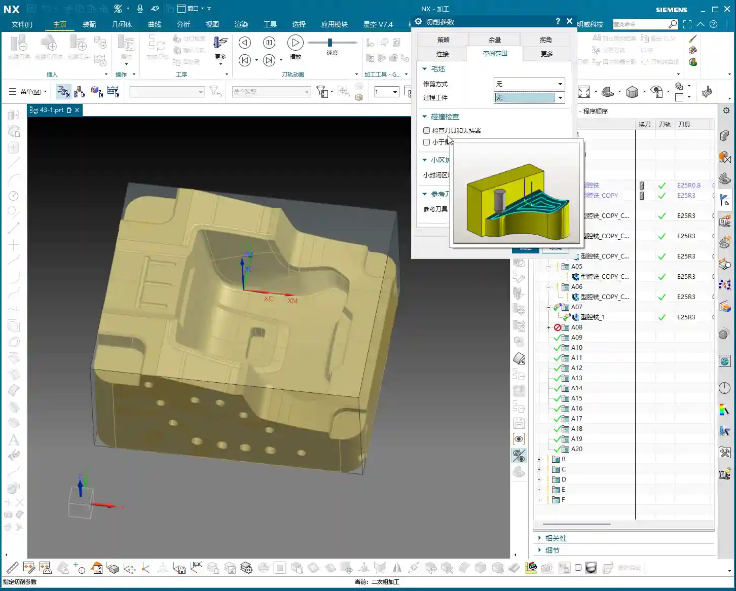
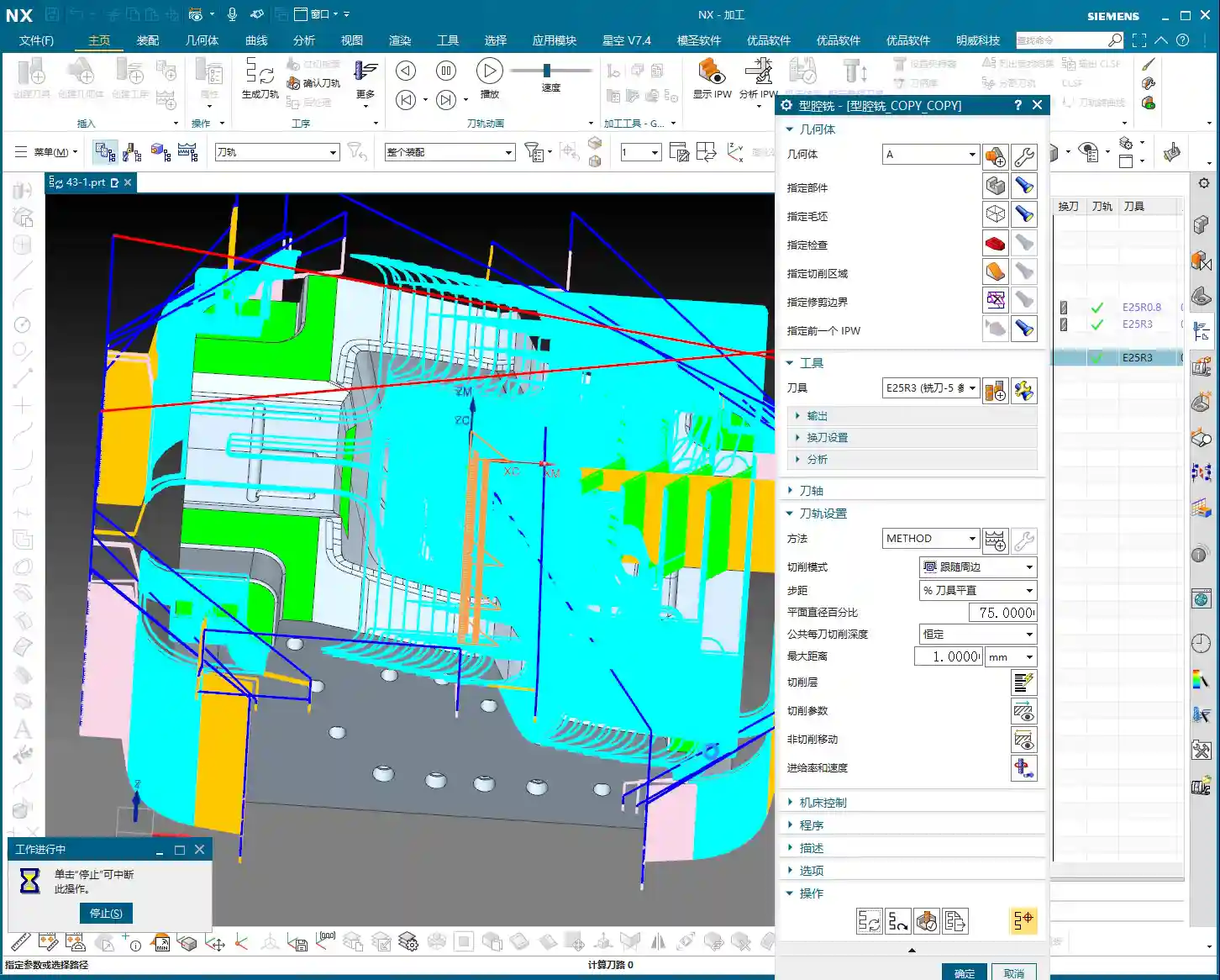
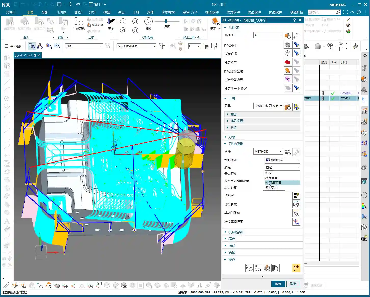
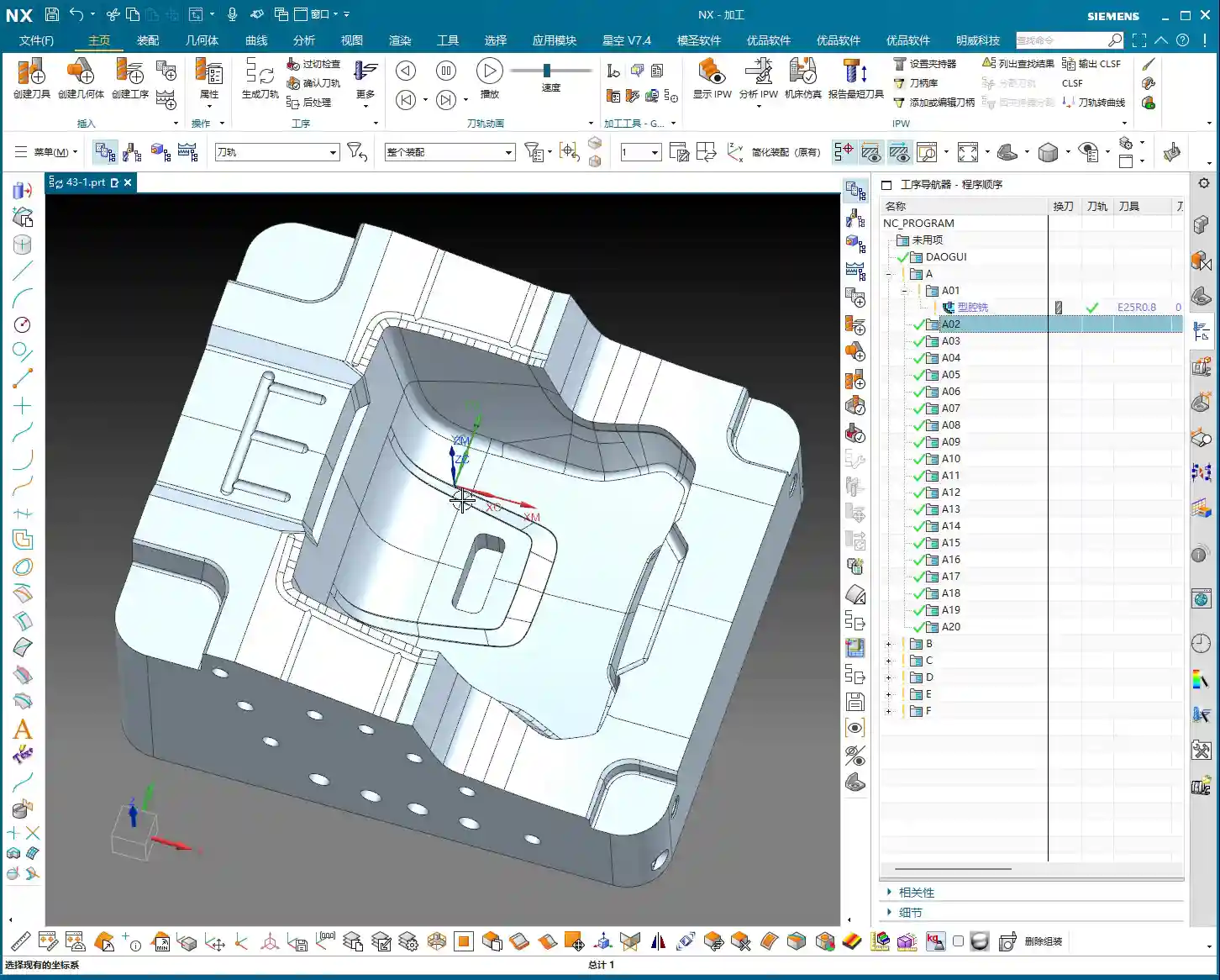
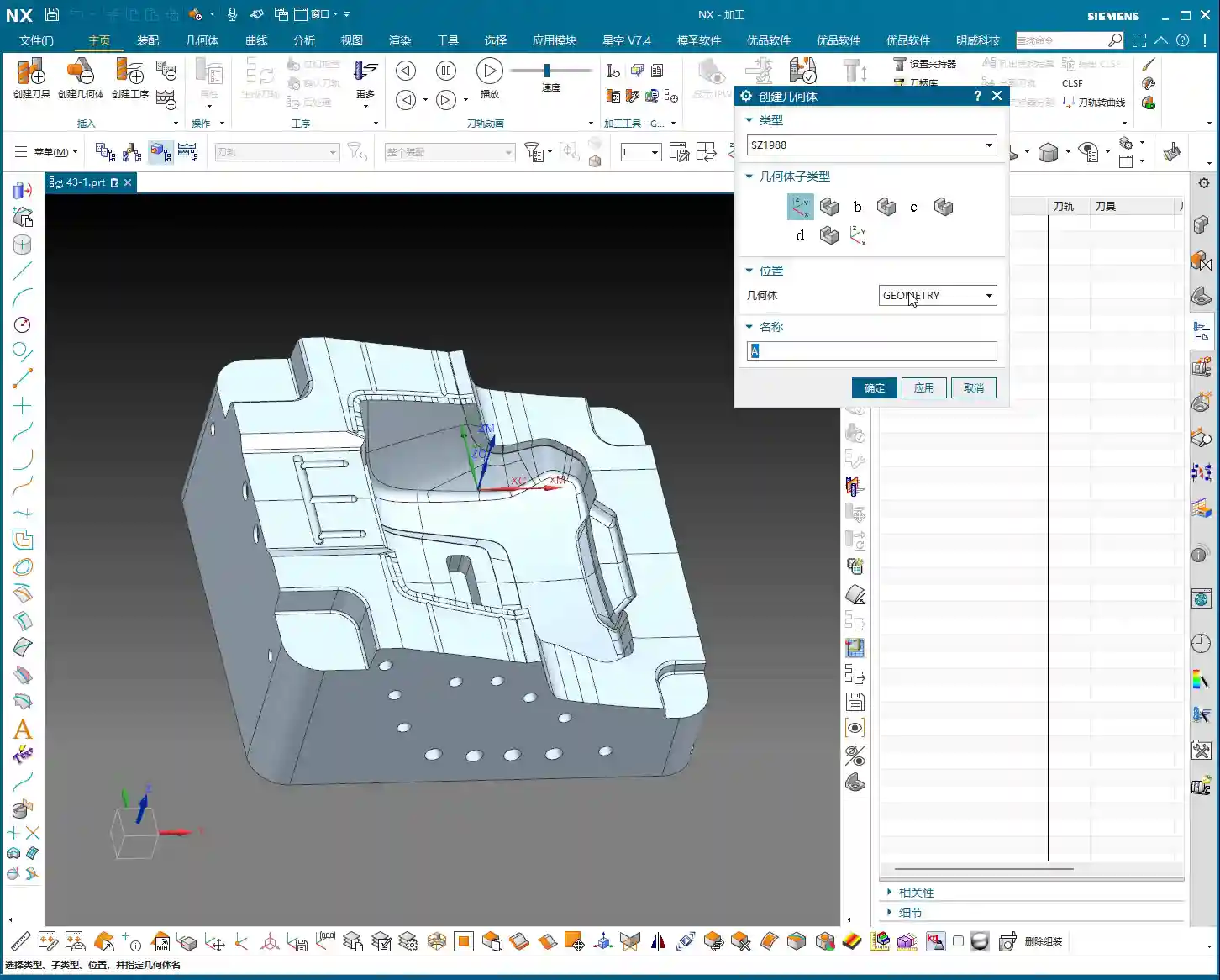
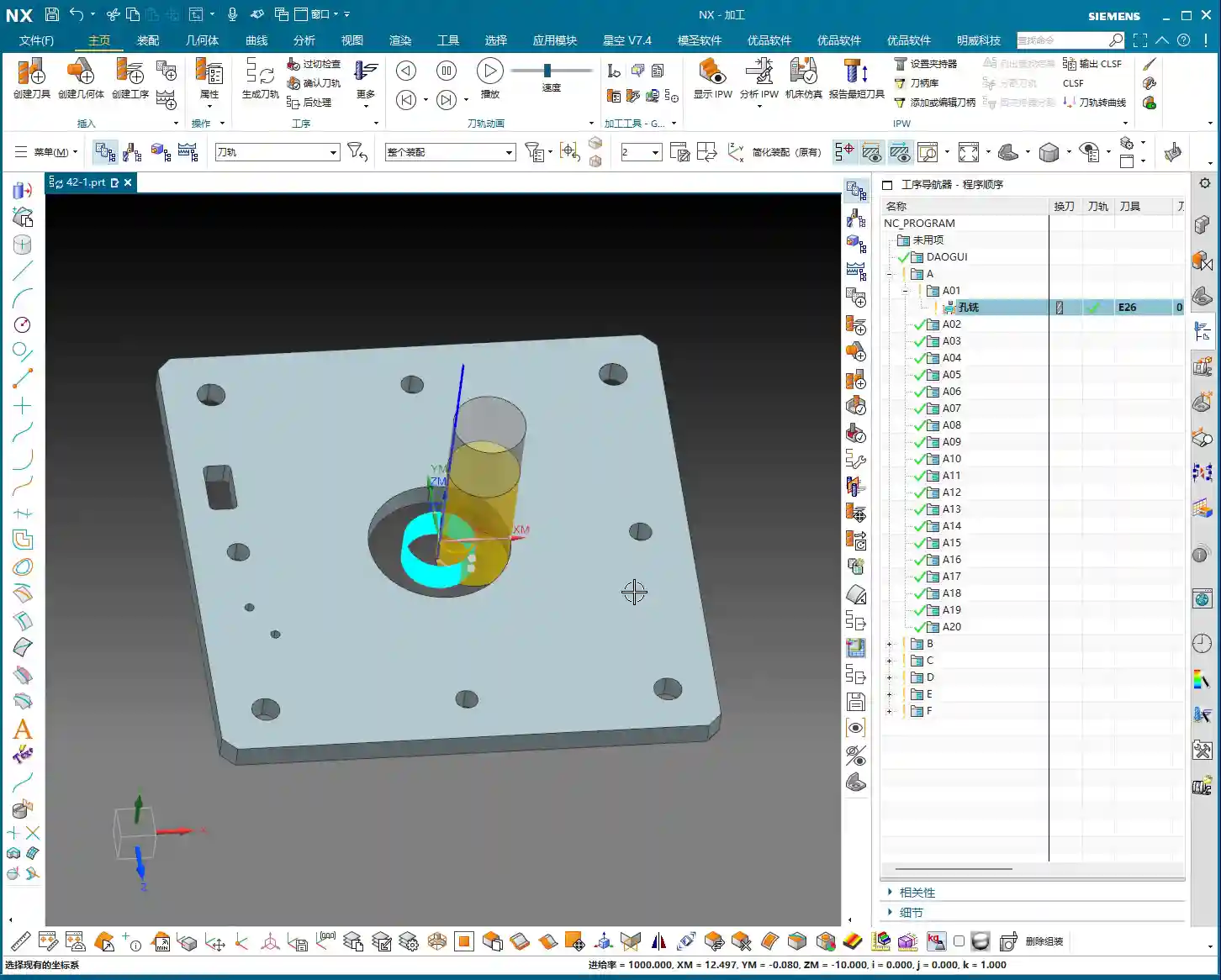
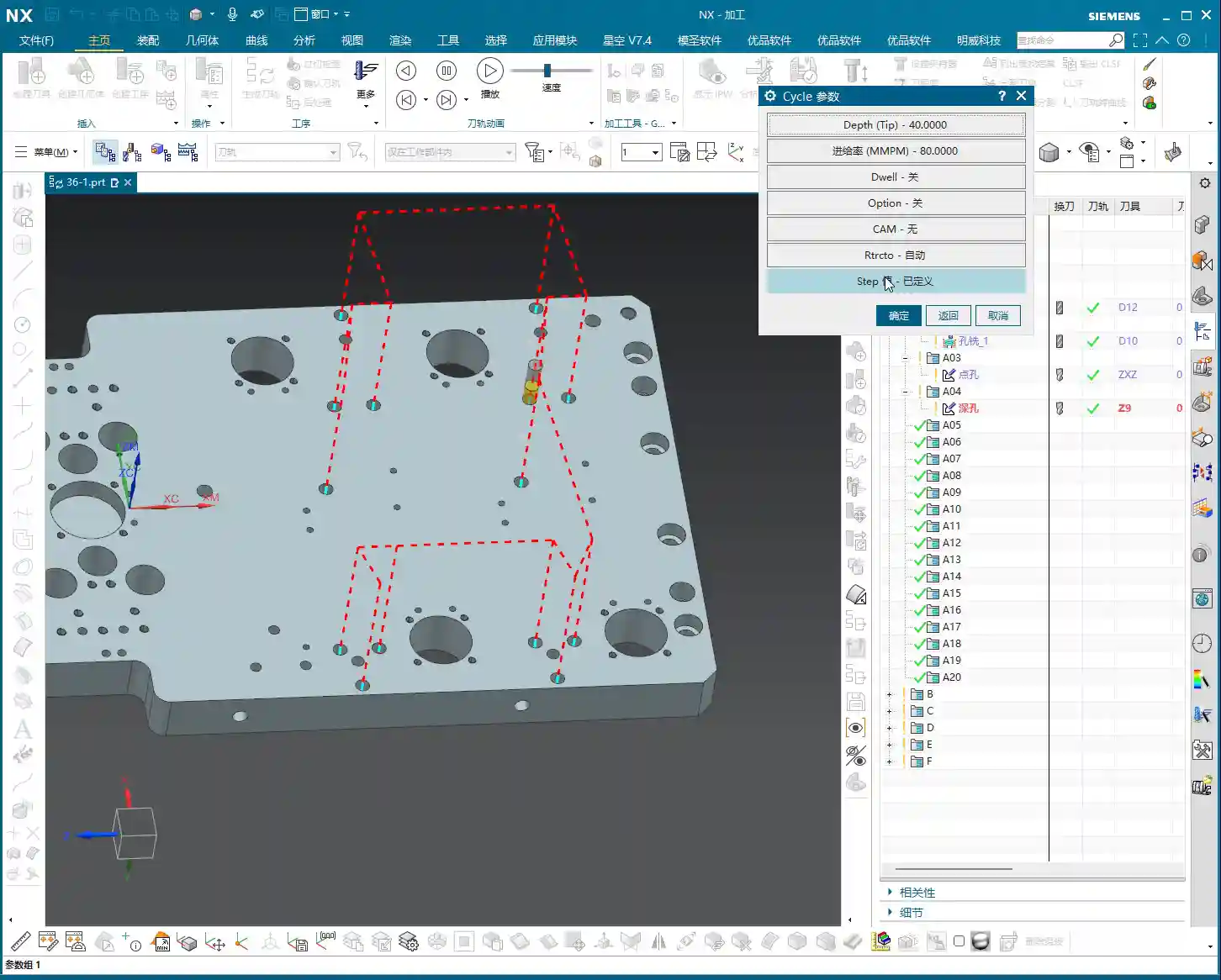
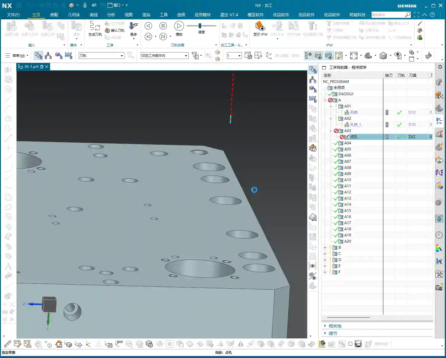
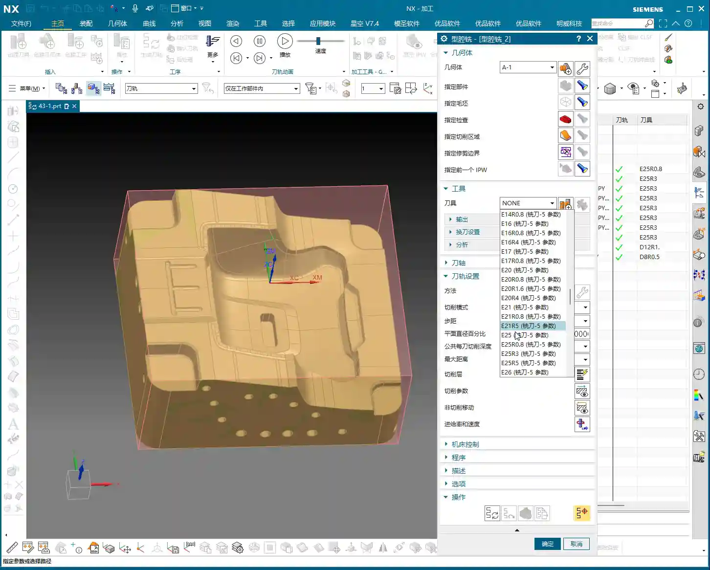
    In Siemens NX, when you’re doing rest roughing in Cavity Milling, besides the “Reference Tool” option, there’s another called “Use 3D” (or a custom name you might have, like my A-20 here, just for differentiation, but it’s the same core function). This “Use 3D” feature has a strict prerequisite: you must first create a Workpiece object. Mark my words, this is mandatory!

    Before, we didn’t really delve into the meaning of the Workpiece, but now, when it comes to Cavity Milling, it becomes absolutely critical. If you want to use “Use 3D” for machining but haven’t set up the Workpiece beforehand, you simply won’t be able to proceed.

    Workpiece Setup and Benefits

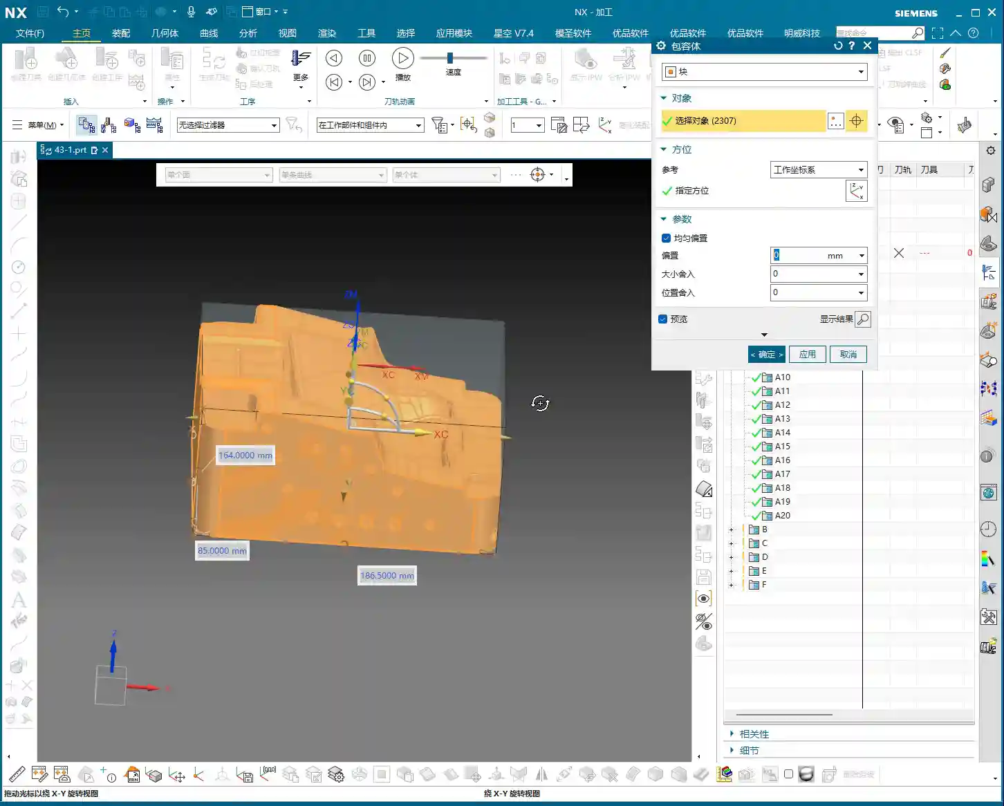
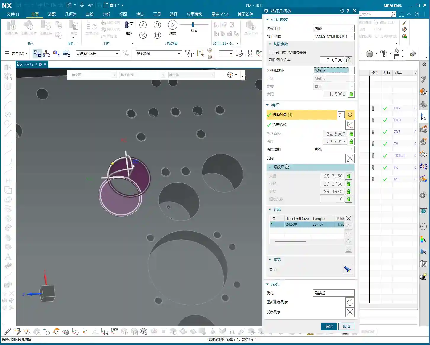
    Open the Workpiece object, and you’ll find two key options: one is Part, and the other is Blank. We often set these in operations before, right? But now, you’re “fixing” them directly within the Workpiece object in advance.

    What’s the benefit? Once you specify the Part and Blank within this Workpiece, when you choose to machine using the “Use 3D” method, for example, operations like A-1 or A-20 as we’re discussing here, it will automatically inherit and recognize the pre-defined Part and Blank from the Workpiece. This saves you the hassle of manually specifying them every time you create an operation, significantly improving programming efficiency, especially for complex parts and multiple operations. Simply put, you do the foundational work upfront, and the rest flows smoothly.

    Two Strategies Head-to-Head: Traditional vs. 3D

    Since we’ve brought up two main approaches, we need to understand their individual characteristics and uses.

    Traditional Reference Tool Machining

    This method is what we’ve used more often – it’s straightforward. When you select “Reference Tool” for roughing, every time you create a new operation, you need to manually specify the Part and Blank. It doesn’t automatically inherit them like “Use 3D.” This approach works fine for simple parts or single operations, but if you have many operations, continually selecting them gets tedious and prone to errors. Furthermore, its precision in handling residual stock is inferior compared to “Use 3D.”

    Advantages of 3D Rest Roughing: Automatic Residual Stock Identification

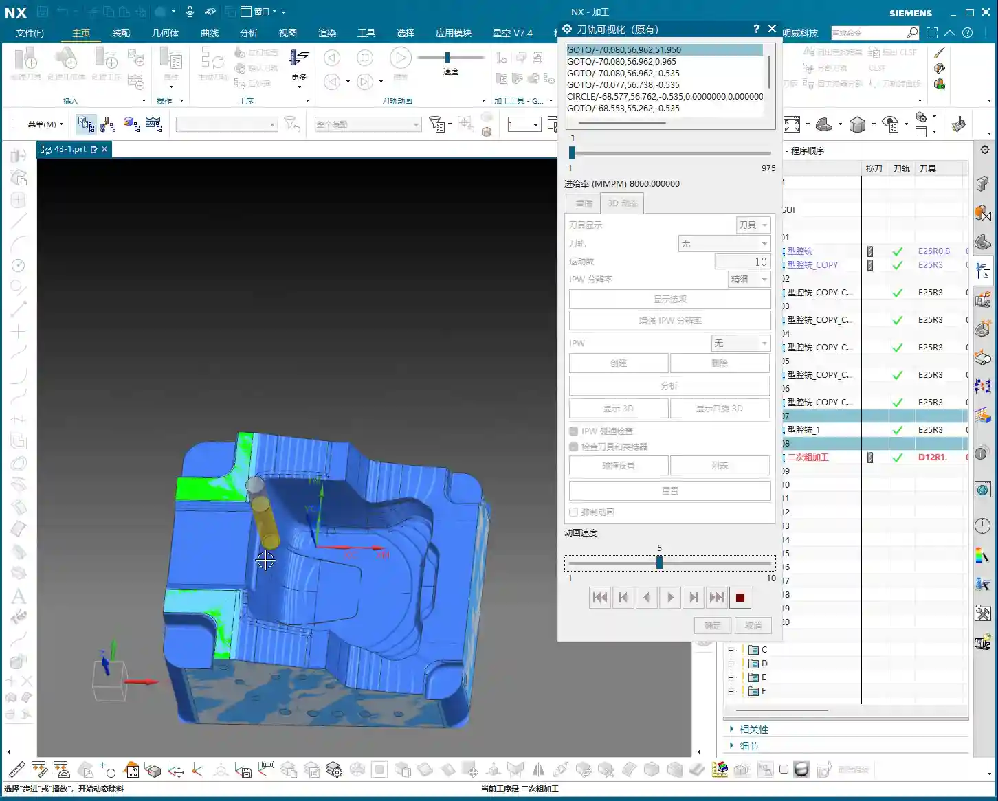
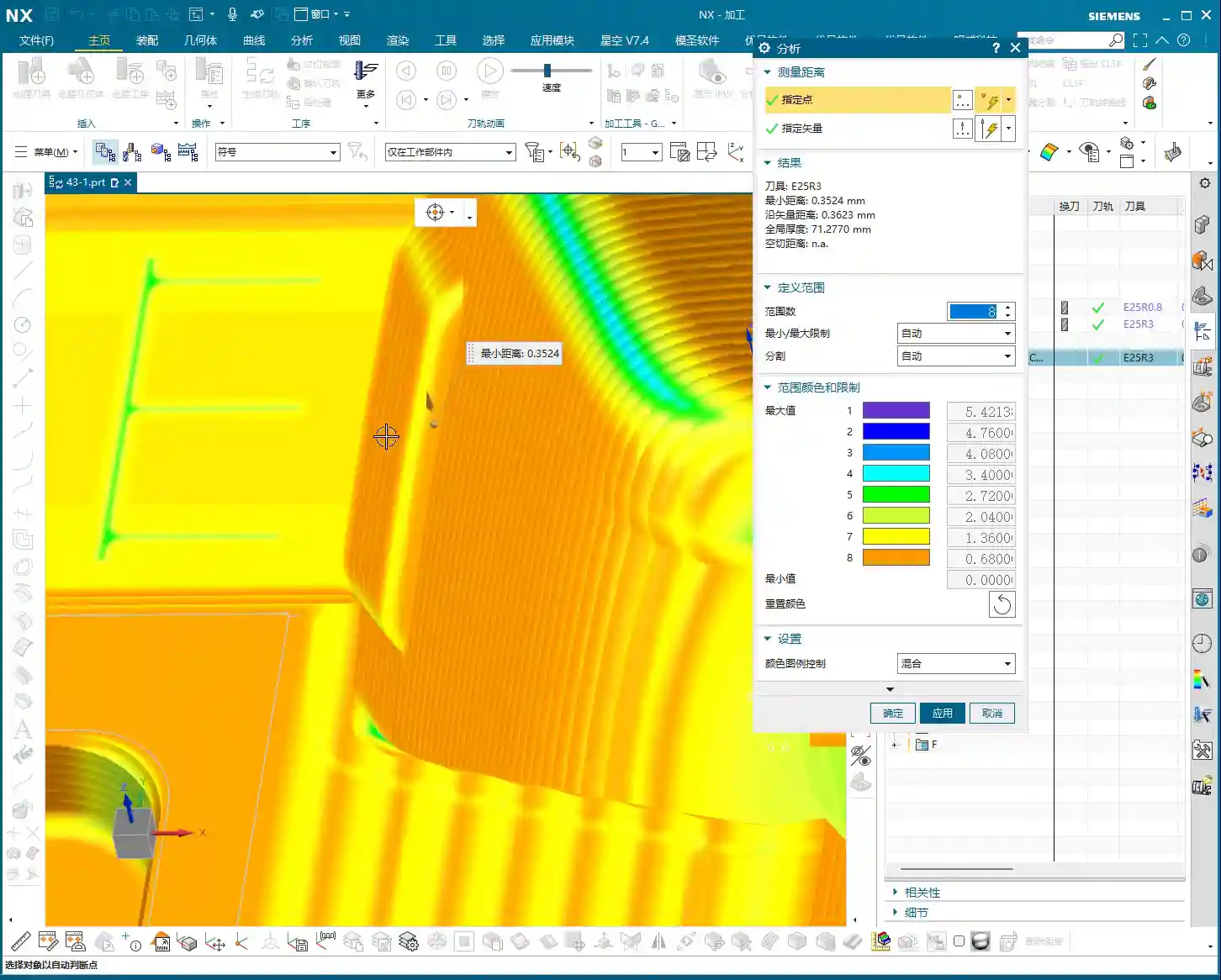
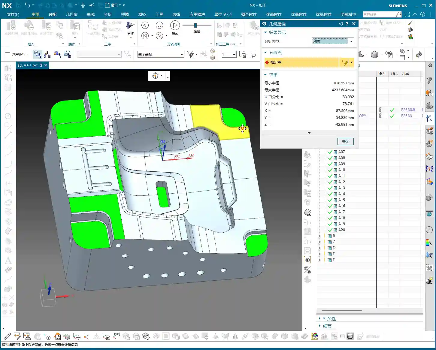
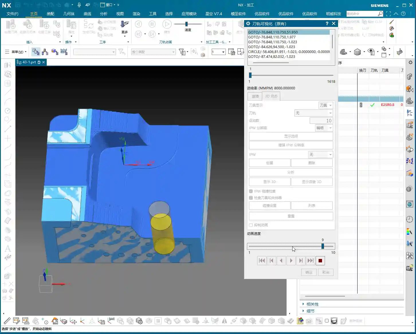
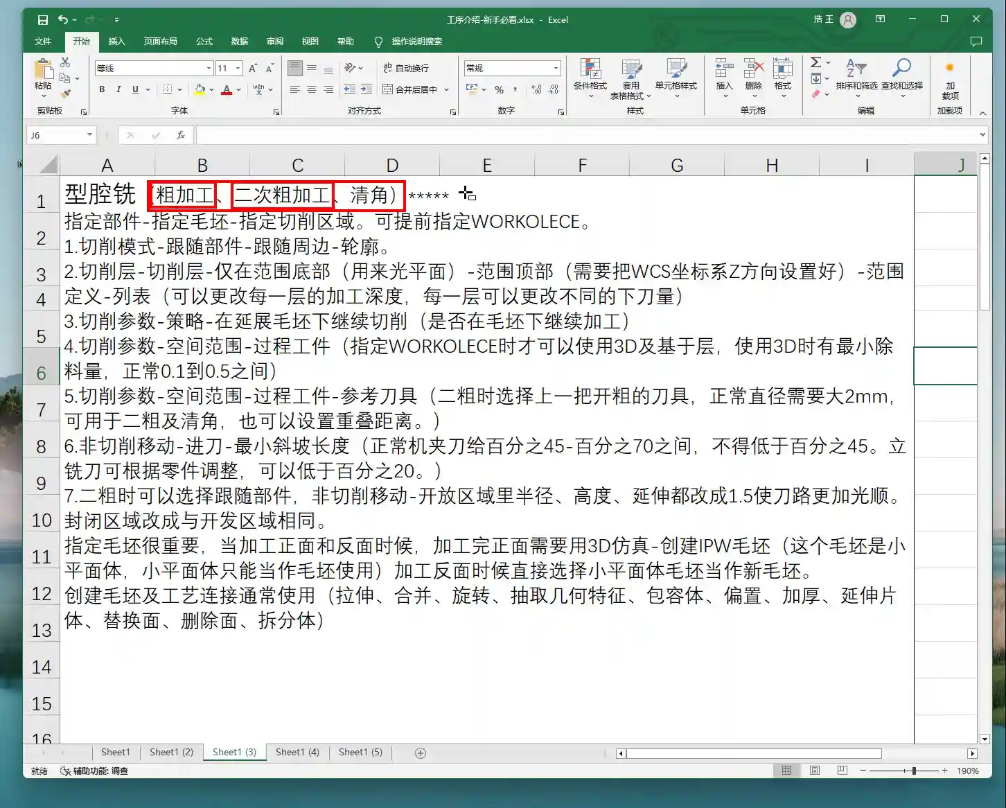
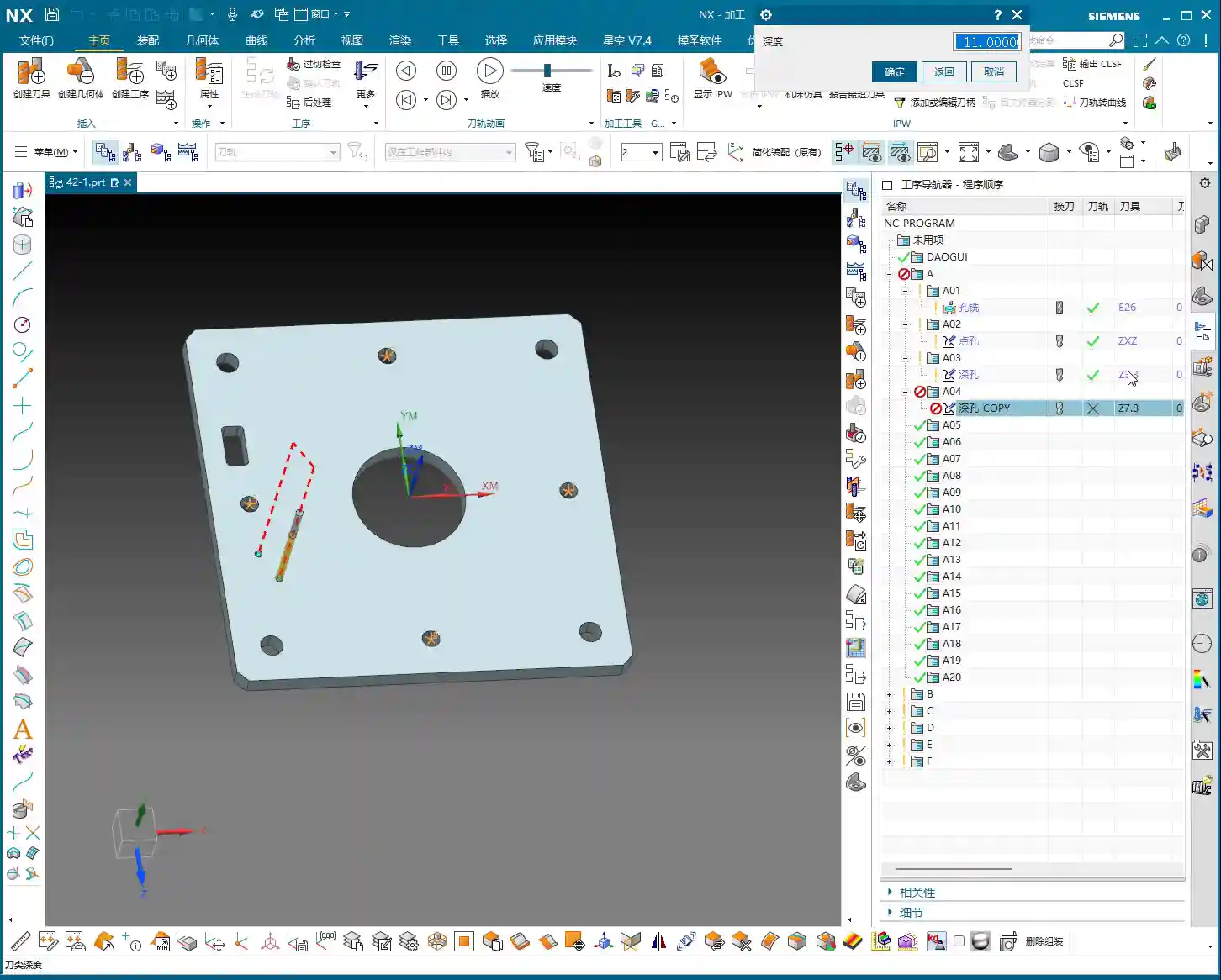
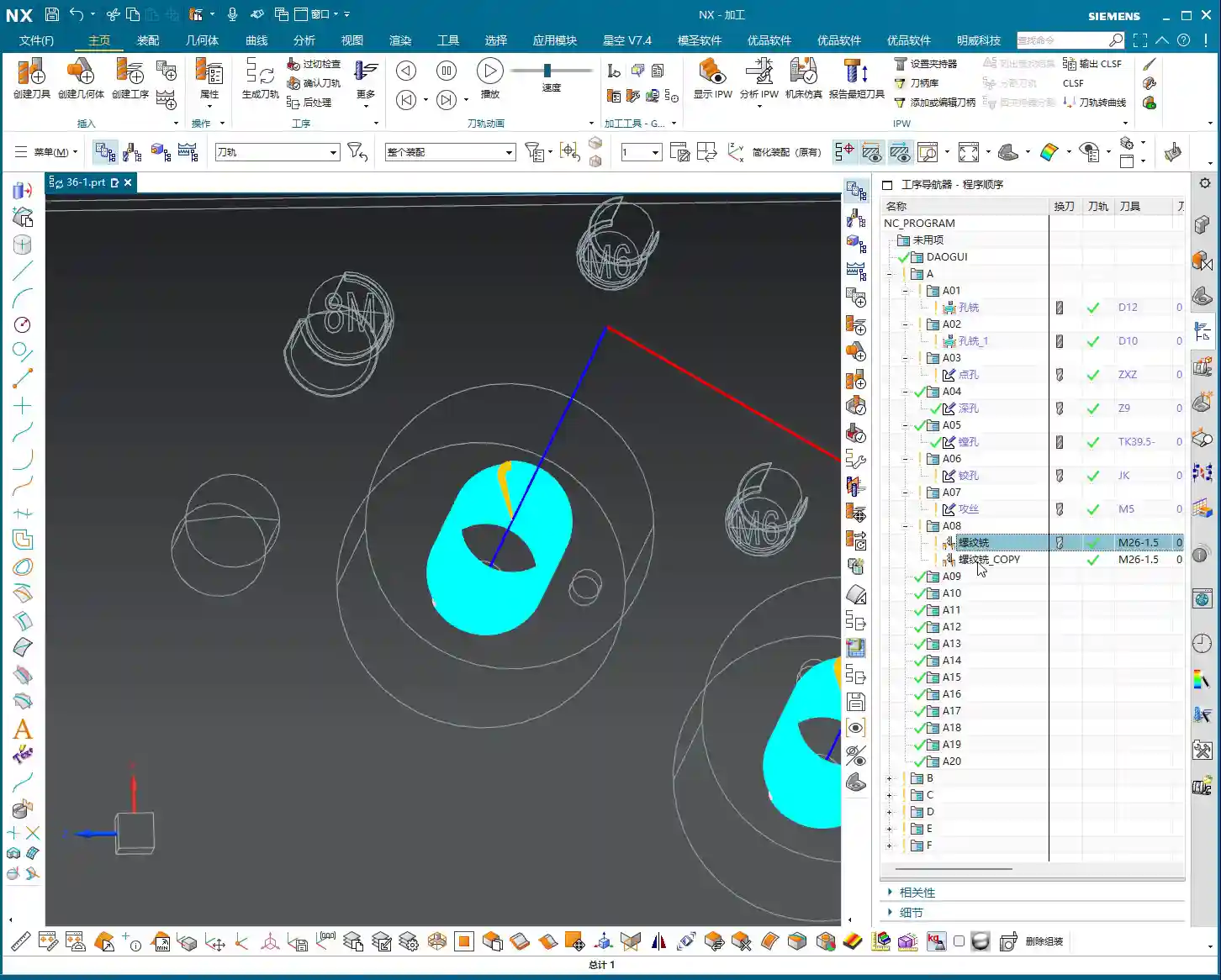
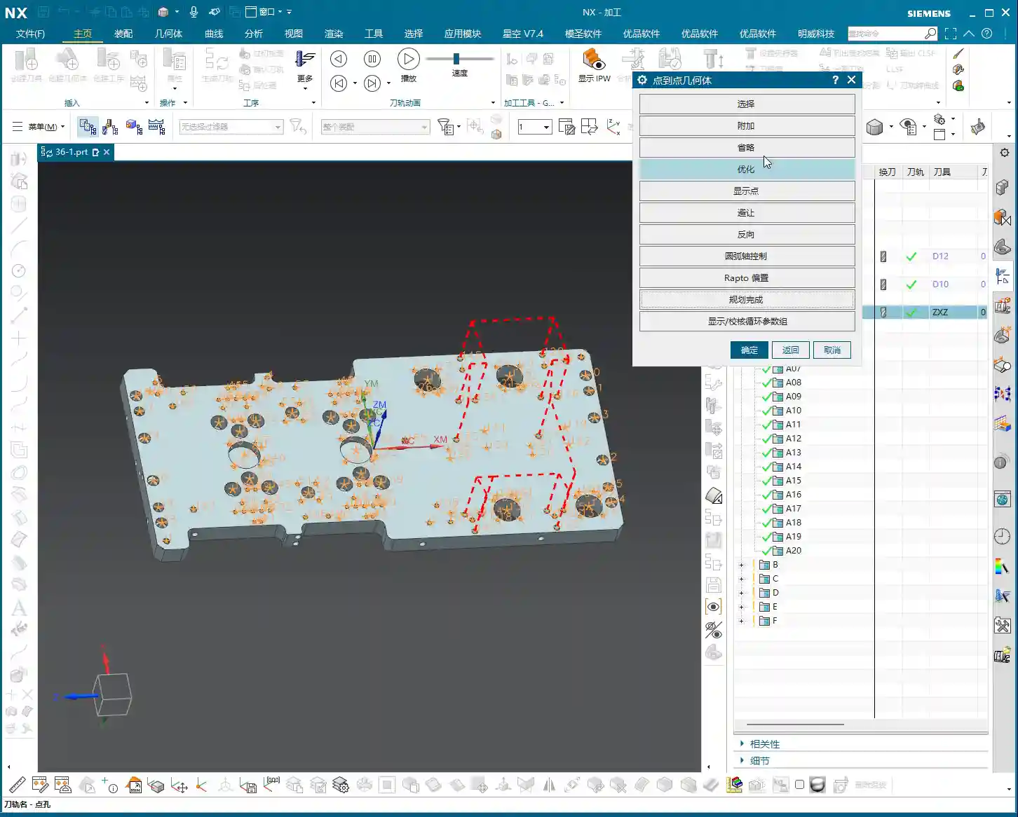
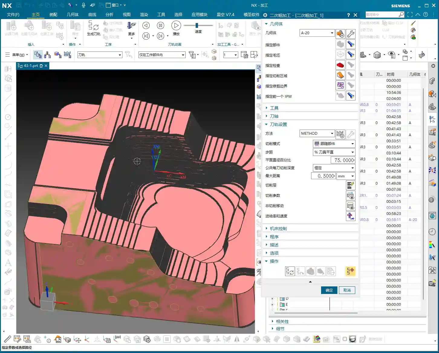
    Here’s the key! When we use “Use 3D” for rest roughing, the most significant advantage is its ability to automatically identify and calculate the residual stock left from the previous operation. You see, when I highlight the blank, it’s no longer a uniform block; it’s the actual shape remaining after the previous roughing pass.

    This is where NX gets smart. It uses the Part and Blank defined in the Workpiece, combined with the machining results from your previous operation, to precisely know where material still remains and where it has already been cleared. This way, you don’t need to manually set the reference tool diameter to simulate the previous machining effect; instead, you rely entirely on the system’s automatic judgment. This is especially effective when machining complex surfaces or deep cavities.

    Refining Toolpaths: Precision and Efficiency in 3D Machining

    “Use 3D” isn’t just about convenience; it also offers unique advantages in toolpath generation and machining quality.

    Precise Handling of Residual Stock

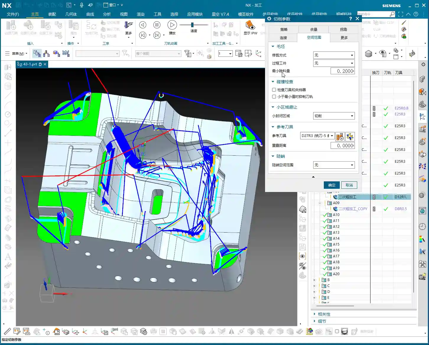
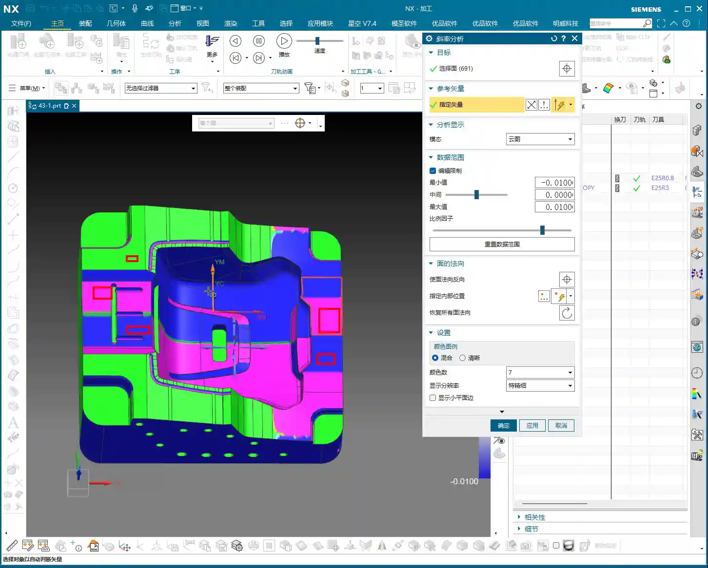
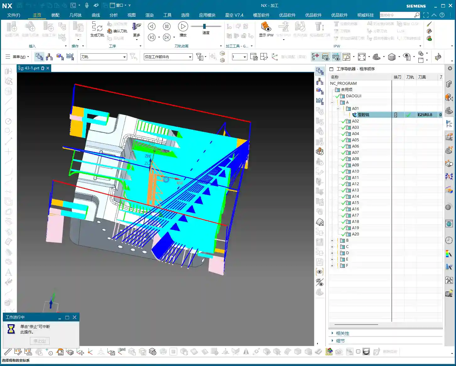
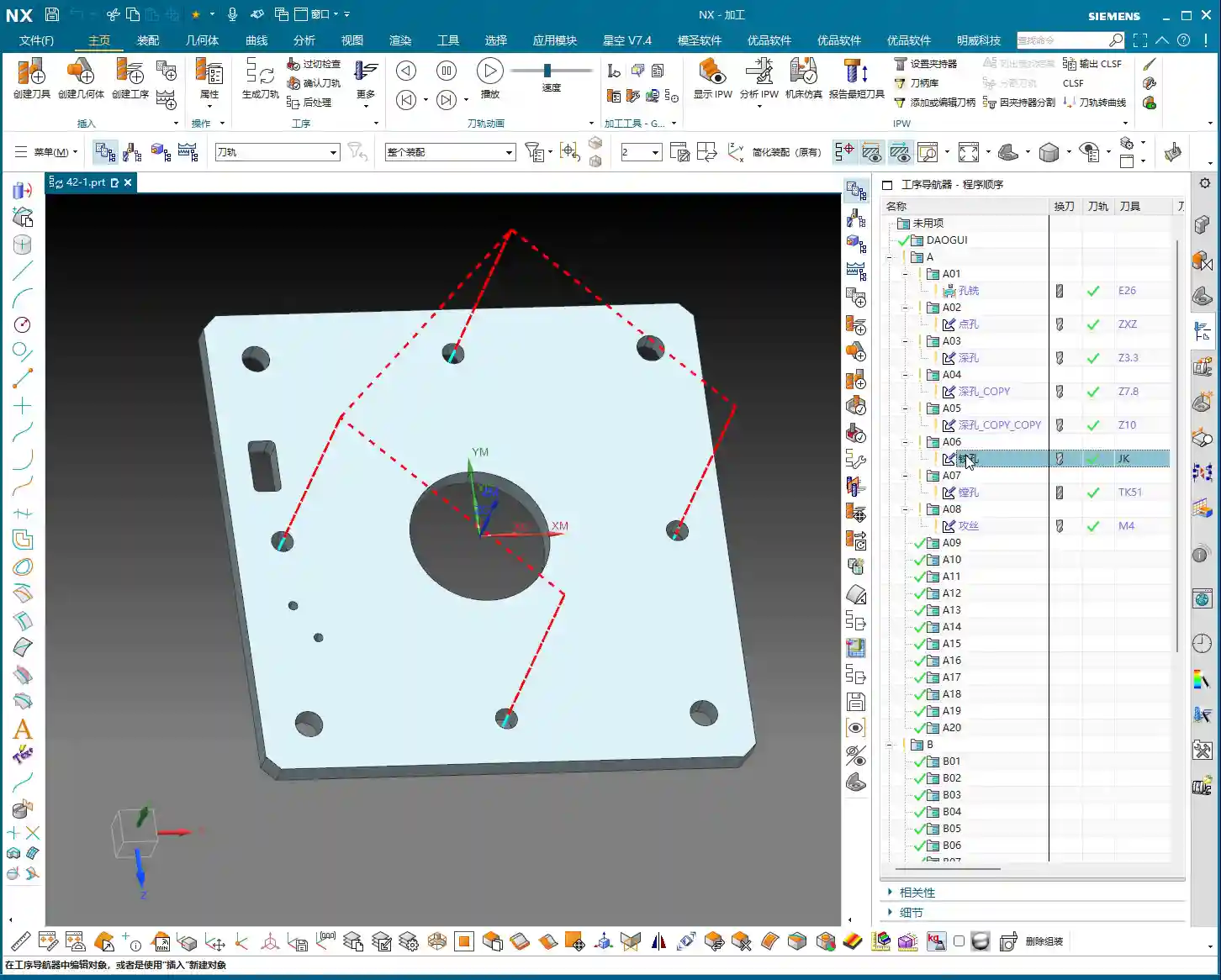
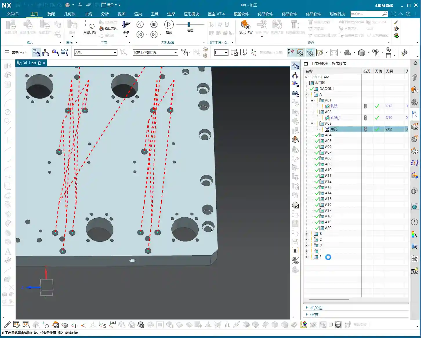
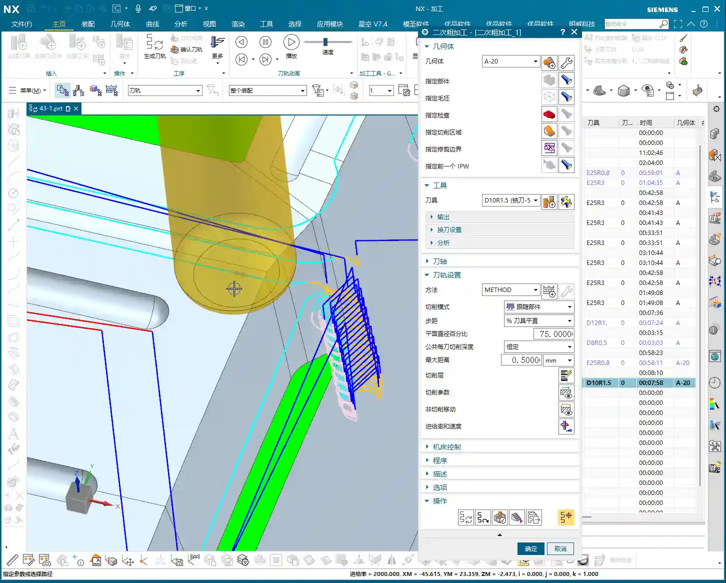
    Traditional machining methods, especially on slopes, small fillet radii, or at the bottom of deep cavities, often leave behind “small triangular areas” or irregular residual stock – places the tool couldn’t completely clear. These areas often pose risks for subsequent operations, potentially increasing the burden of finishing, or worse, leading to gouging, tool chipping, or even scrapping the part.

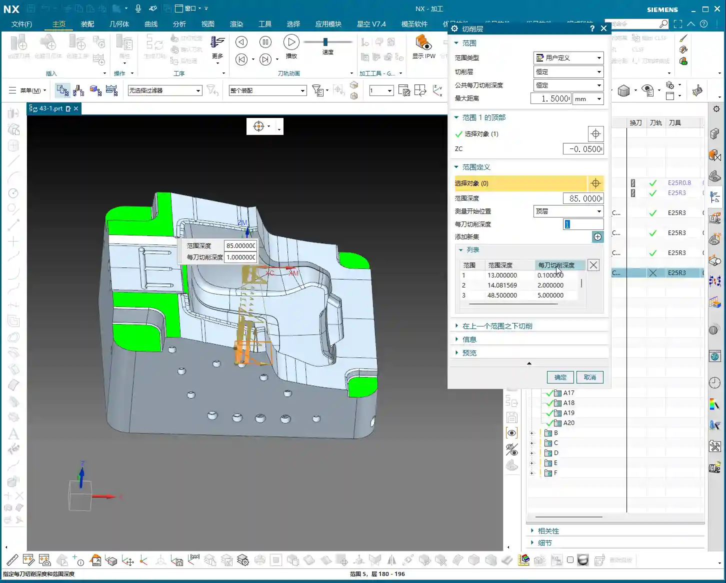
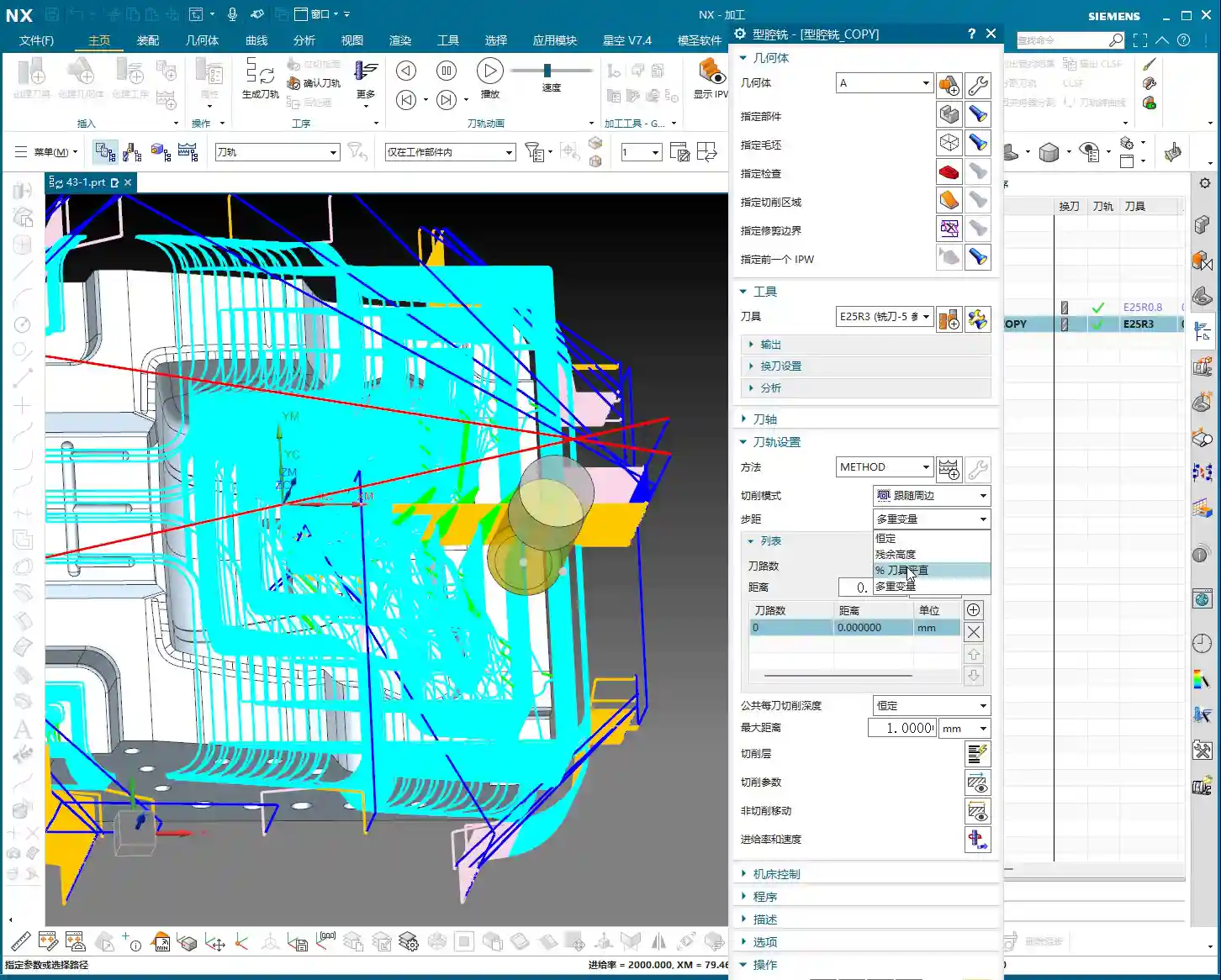
    However, “Use 3D” machining, precisely because it calculates the residual stock, will specifically generate additional cuts for these irregular, unmachined regions when creating toolpaths. For instance, steep slopes that traditional methods might skip over will get an extra pass with 3D roughing to clear that material as well. This results in more uniform residual stock on the part surface, laying a better foundation for subsequent finishing passes. The toolpath might look denser, but it’s genuinely clearing material.

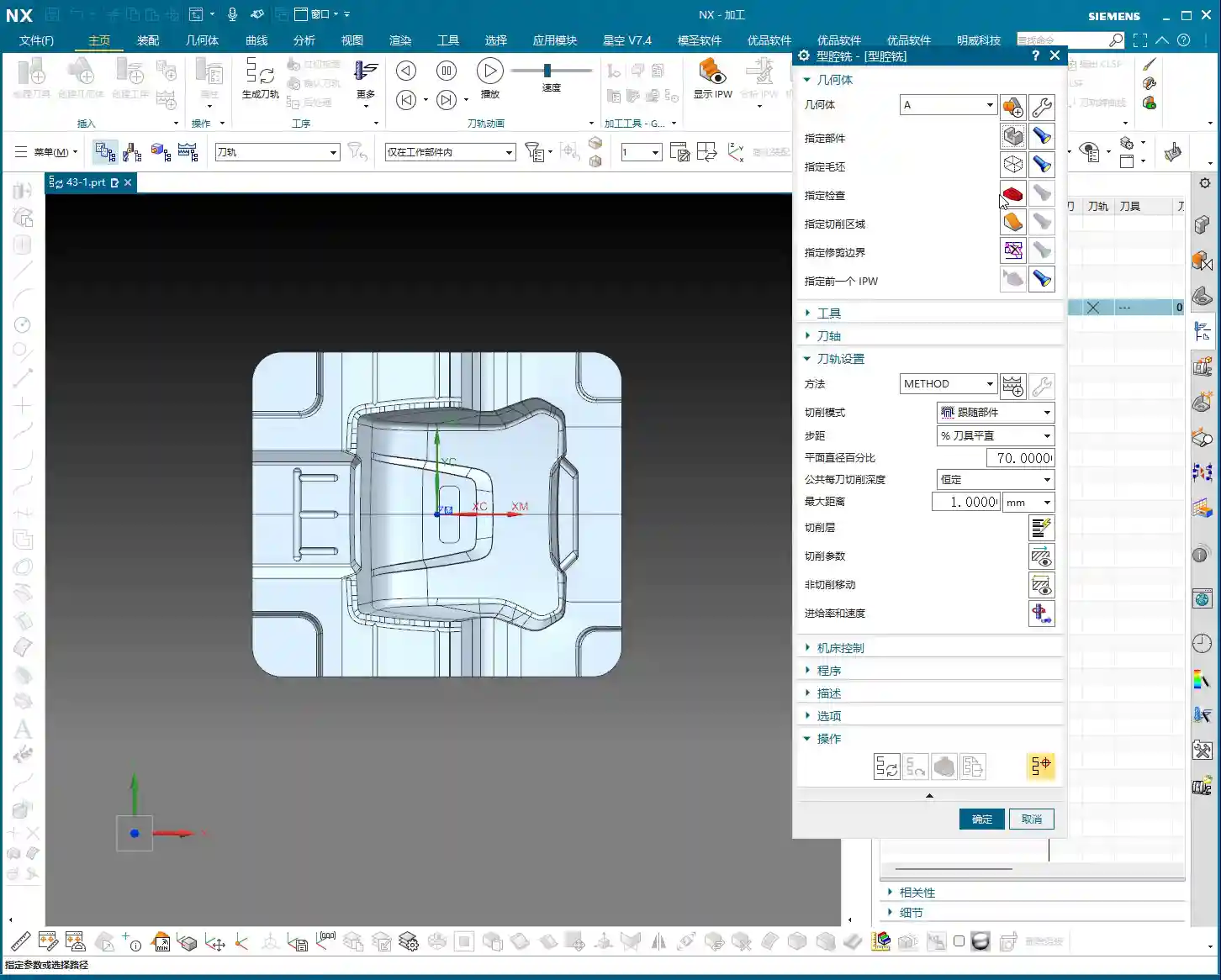
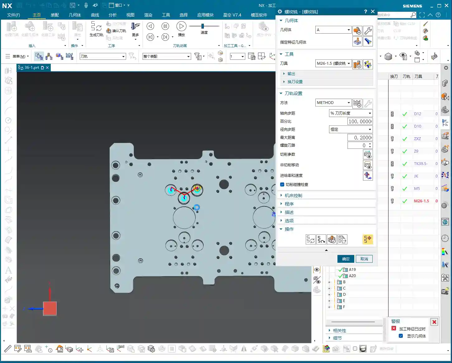
    Optimization Strategies and Computational Considerations

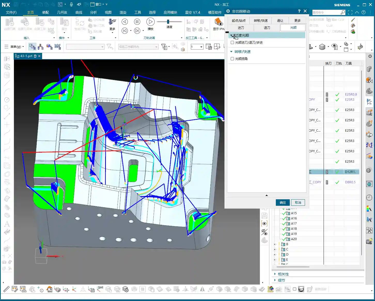
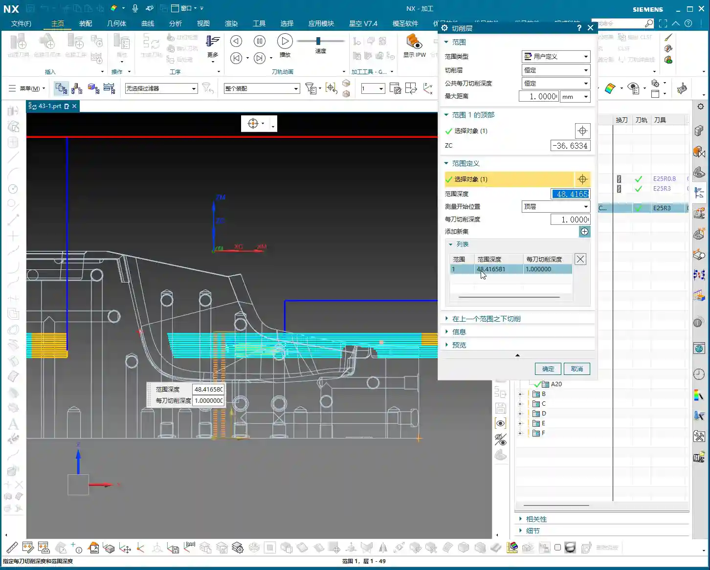
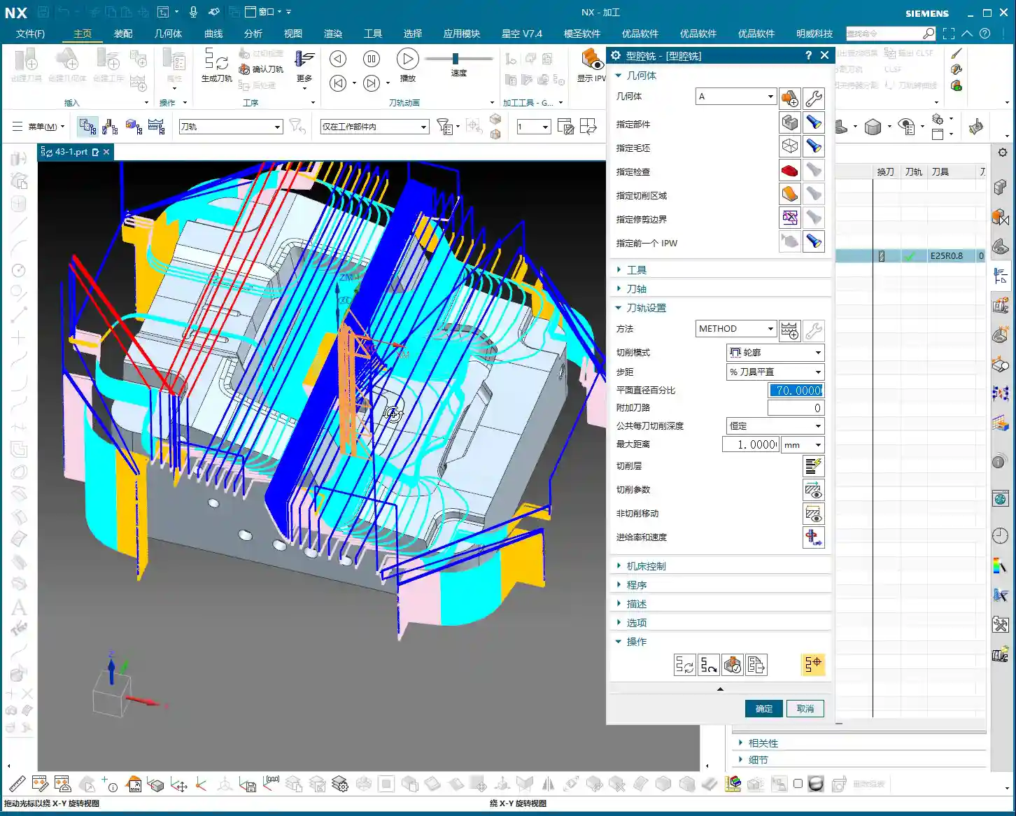
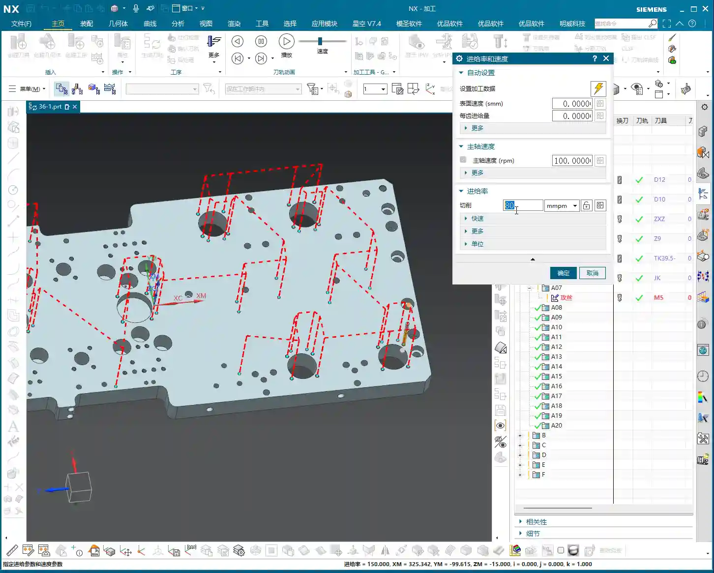
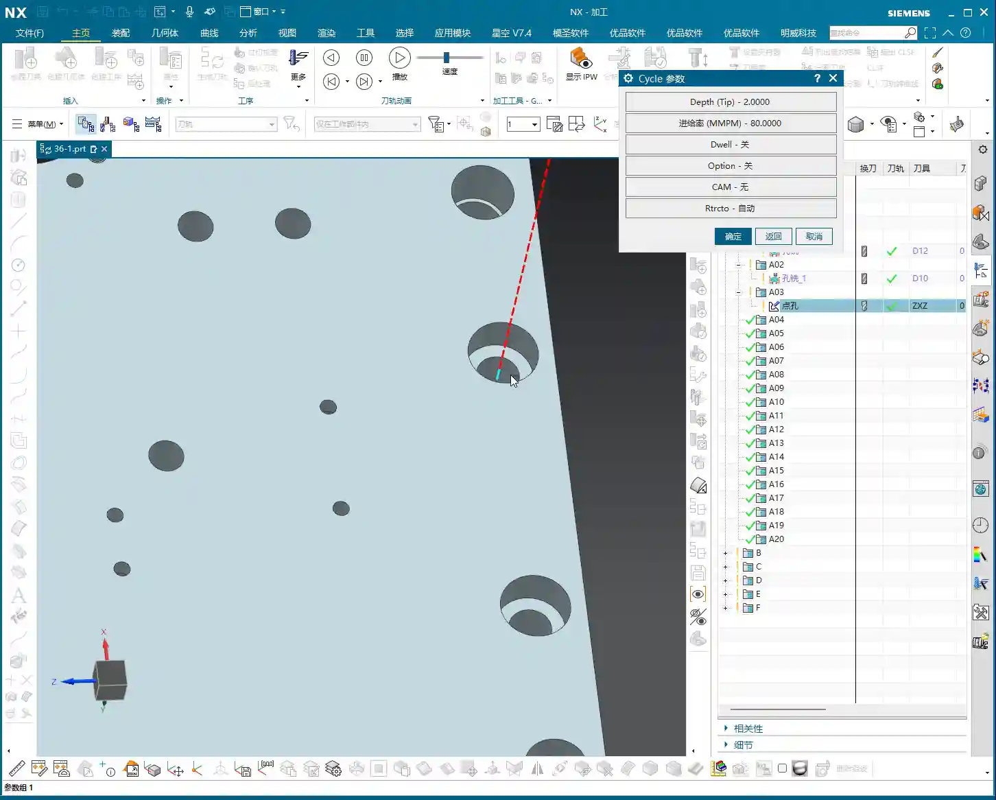
    While “Use 3D” can handle residual stock more precisely, don’t forget it’s computationally more intensive, so program generation time might be longer. But it’s absolutely worth it! To further optimize, we can adjust the parameters.

    For example, for the Depth of Cut (DOC) or Stepover, you can adjust them according to the actual situation. I usually set the stepdown for rest roughing to half of the initial roughing, or slightly smaller based on material hardness and tool wear, such as 0.4mm. This way, while ensuring effective material removal, you can also optimize toolpath density and reduce unnecessary air cuts, improving overall efficiency. Don’t just rely on software simulations; look at the cutting sparks, listen to the machine’s sound – that’s the real validation!

    Summary: Pitfalls to Avoid

    1. Workpiece is Fundamental: Listen up, if you want to use the “Use 3D” function, the first step is always to define your Workpiece, including the Part and Blank. If it’s not set up correctly, everything else is pointless.
    2. Understand Both Methods: “Reference Tool” is suitable for simple parts or beginners, requiring manual selection every time. “Use 3D” is advanced; it automatically inherits and identifies residual stock, significantly improving efficiency and machining quality.
    3. Refined Toolpaths: 3D rest roughing helps clear those “small triangular areas” and irregular remnants, preventing gouging during finishing. But remember, calculation time will be slightly longer; this is normal.
    4. Parameter Flexibility: Don’t rigidly apply default parameters. Stepdown, feed rates, etc., should be adjusted flexibly based on the material, tooling, and conditions of the previous operation. For example, setting the stepdown for rest roughing to half of the initial roughing can effectively optimize toolpaths and reduce air cuts.
    5. Experience is Key: Don’t just stare at the screen watching simulations; go to the machine and observe the actual cutting performance. Are the sparks consistent? Is the machine experiencing unusual vibration? These are the ultimate criteria for judging a good toolpath!
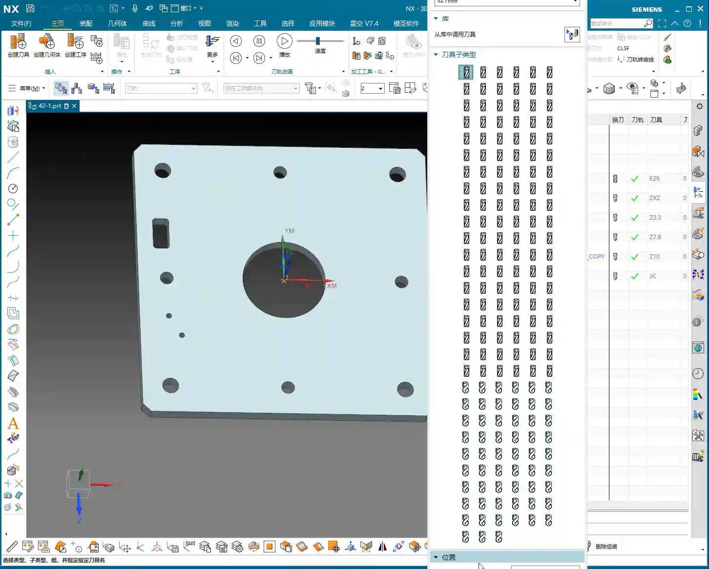
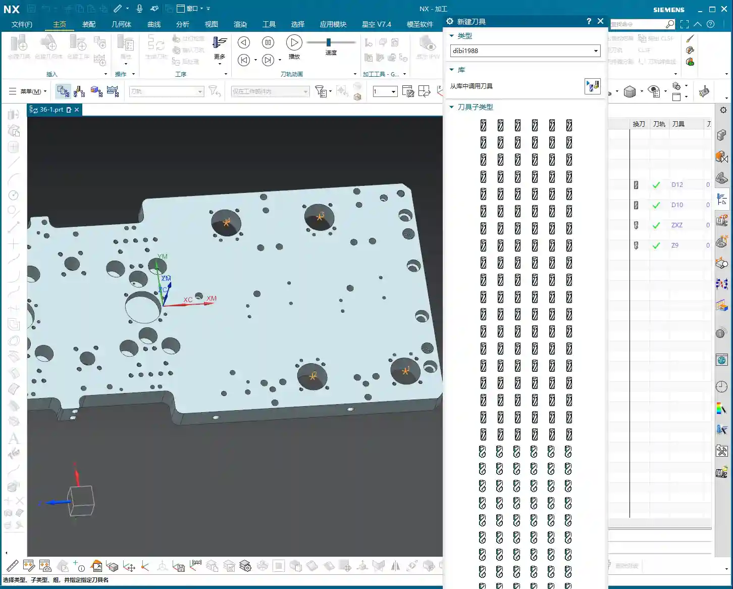
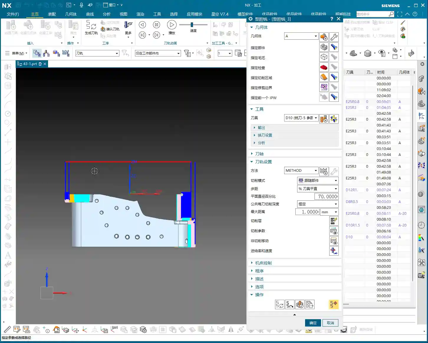
    6. Tool Limitations: Finally, even with 3D rest roughing, if the tool diameter is too large, it still can’t access some narrow areas. Remember, tools are not universal; select them appropriately based on the geometry.

    👤 About the Author:
    The author is a veteran CNC machining professional with 15 years of industry experience, specializing in UG NX programming. This article is an original work representing personal practical insights.

    ⚠️ Copyright Notice: Unauthorized reproduction or distribution without prior communication is strictly prohibited.

  • Siemens NX Cavity Milling Rest Roughing Practice Guide: Master Wang Teaches You Clever Use of Refere

    📝 Key Takeaways: Master Wang personally guides you through practical techniques for Siemens NX cavity milling rest roughing, from correctly selecting commands and setting up stock, to a core explanation of “In-Process Workpiece” and “Reference Tool.” He reveals the “Minimum Residual Material” parameter, helping you optimize toolpaths, efficiently perform corner cleanup, thoroughly eliminate unmachined areas, and achieve high-quality part machining.

    Hello everyone, I’m Master Wang. Last time, we pretty much covered roughing; today, we’ll continue with rest roughing. Don’t underestimate it – when used well, this technique can save you a lot of finishing time and effectively improve the part’s surface quality.

    Rest Roughing Operation: Siemens NX Command Selection and Initial Setup

    Listen closely: for rest roughing in NX, we’ll directly choose the “Cavity Milling Rest Roughing” command. Simply put, it’s a branch of cavity milling, but NX engineers have pre-set some parameters for you, making it more suitable for corner cleanup and processing material left from the previous roughing pass. If you were to use it for initial roughing, it’s not impossible, but you’d have to change a bunch of parameters—why create trouble for yourself? It’s time-consuming, laborious, and not worth it!

    • Operation Entry: Directly select “Cavity Milling Rest Roughing”.
    • Stock and Part: This section is the same as the initial roughing; just click OK, no need to change. The system will default to your previous settings.
    • Tool Selection: Rest roughing, as the name suggests, is used to clear corners unreachable by the large tool during the previous roughing pass. Therefore, you need to select a tool with a smaller diameter, typically a ball end mill or bull nose end mill, and a smaller corner radius (R value) than the roughing tool. For example, if you used a D25R3 for roughing, you might consider a D12R1 for rest roughing.
    • Cutting Parameters:

      • Cut Pattern: Generally, use “Contour Part”; this is the most common method.
      • Depth of Cut (DOC): This parameter is crucial. We typically set it to around 0.5mm, depending on material hardness and tool strength. Don’t make it too large; corner cleanup is not about aggressive roughing, it needs to be stable.
      • Cutting Depth: If there are no special requirements, such as not wanting to mill a deep hole all the way through, or if a specific area has depth restrictions, then usually keep the default. Don’t change it arbitrarily, or the toolpath will be messy.

    Core Secrets: Correct Usage of In-Process Workpiece and Reference Tool

    Alright, now let’s talk about the two most critical points for rest roughing, where many novices often stumble. Listen up!

    “In-Process Workpiece”: The “Eyes” of Rest Roughing

    Why is it that even though you’ve set up rest roughing, the toolpath isn’t calculated? Or it calculates a bunch of redundant toolpaths? The problem lies here:

    • Core Setting: In the rest roughing parameter settings, find the “Geometry” tab, and set “In-Process Workpiece” to “5”! Remember, it’s the number “5”!
    • Principle: Setting it to “5” tells the system: “Hey, I’ve already machined this with a previous tool; now, show me where the unmachined residual material is, and only machine those areas!” If you don’t set it to “5”, the system won’t know what you did before; it will treat it as initial roughing, and naturally, it will get confused, either failing to calculate a toolpath or generating a bunch of useless ones.

    “Reference Tool”: The “Compass” of Rest Roughing

    Just setting “In-Process Workpiece” isn’t enough; you also need to point it in the right direction.

    • Function: The “Reference Tool” tells the system which tool was used previously and its size. Based on the shape and size of this reference tool, combined with the “In-Process Workpiece” instruction, the system can accurately calculate where residual material remains and needs to be cleared by the current smaller tool.
    • Selection Technique:

      • First Rest Roughing Pass: Select the large tool you used for the previous roughing pass. For instance, if you used a D25R3 for roughing, then for the first rest roughing pass, select D25R3 as the reference tool.
      • Multiple Rest Roughing Passes: If you need to perform multi-level rest roughing (e.g., D25R3 → D12R1 → D8R1), then each level of rest roughing must reference the machining tool from its preceding level. For example, when using a D8R1 for rest roughing, the reference tool should be D12R1.
      • Create New Tool: If the corresponding reference tool isn’t in your library, simply create a new one and ensure the parameters are set correctly. The important thing is that the parameters accurately reflect the dimensions of the previous tool.

    • Engagement Strategy: For parameters like “Plunge Engage”, I typically set it to 1mm to ensure stable engagement and prevent excessive cutting impact.

    Striving for Excellence: Toolpath Optimization and Practical Experience

    The Secret of “Minimum Residual Material”

    This parameter is also a critical one; often, an unclean toolpath or mysterious small paths are related to it.

    • Definition: “Minimum Residual Material” means that if the thickness of the material remaining in a certain area after the previous machining is smaller than the value you set, then the current tool will not machine it.
    • Application: For example, if you set it to 0.2mm, then areas with only 0.1mm or less material remaining will be considered by the system as “not necessary to cut, leave it for finishing or the next smaller tool,” and thus ignored.
    • Master Wang’s Experience:

      • This value should typically be set to half of the previous tool’s “Depth of Cut” (DOC), or slightly less than the corner radius of your current machining tool.
      • For example, if the previous tool’s DOC was 1mm, then this value can be set to 0.5mm, or even slightly smaller like 0.4mm or 0.3mm.
      • Setting this value appropriately can effectively prevent the tool from cutting tiny scraps, which wastes time, causes tool wear, and reduces efficiency.

    “Trim Boundaries”: A Great Helper for Streamlining Toolpaths

    Rest roughing toolpaths can sometimes be a bit redundant, especially in less critical areas.

    • Function: Through “Trim Boundaries”, you can manually specify a point or area to make the tool avoid these places and stop generating toolpaths there.
    • Purpose: This helps you optimize the toolpath, making it more streamlined and efficient. Sometimes, the residual material in certain areas doesn’t need to be cleared again, or you want to handle it in another way, so you can trim it.

    Multi-Level Rest Roughing: Layer by Layer, Step by Step

    For complex cavities or high-precision requirements, a single rest roughing pass is often insufficient. We can proceed layer by layer, like peeling an onion, to go deeper.

    • Approach: You can duplicate the current rest roughing operation, then switch to a smaller tool, and simultaneously update the “Reference Tool” to the machining tool from the previous level.
    • Example:

      1. D25R3 roughing.
      2. D12R1 rest roughing, referencing D25R3.
      3. D8R1 rest roughing, referencing D12R1.

      This is called a “Corner Cleanup Sequence”, which ensures every corner is thoroughly cleared, laying a solid foundation for the final finishing pass.

    Allowance Control: Making Toolpaths Smoother

    Here’s another small detail that can make your rest roughing toolpaths “smarter.”

    • Master Wang’s Experience: During rest roughing, the allowance left should ideally be slightly smaller than during initial roughing. For example, if roughing leaves 0.35mm, rest roughing can leave 0.25mm or 0.2mm.
    • Benefit: Doing so prevents the tool from repeatedly cutting areas that have already been cleared, making the toolpath smoother, reducing air cutting, and improving efficiency.

    Machining Simulation and Verification

    NX’s simulation function is very powerful, but don’t just watch it run through once and call it a day.

    • Key Point: During simulation, pay special attention to the tool’s movement in complex areas like corners and deep cavities. Compare before and after rest roughing to see if the residual material in these areas has been effectively removed.
    • Details: Some subtle residual material might only be discovered by zooming in and carefully observing the simulation. Don’t rely solely on software simulation; during actual machining, you also need to observe cutting sparks and listen to cutting sounds—those are the most authentic feedback.

    Master Wang’s Summary: Pitfall Avoidance Guide

    In our line of work, theoretical knowledge alone isn’t enough; practical experience is key. For today’s rest roughing, just remember these points to ensure you take the shortest path to success:

    1. In-Process Workpiece: Always “5”! This is the soul of rest roughing; without it, everything else is moot.
    2. Reference Tool: Absolutely select the tool actually used in the preceding machining level. This is the eyes of rest roughing, telling the system where material still remains.
    3. Minimum Residual Material: Set it appropriately, usually smaller than the previous tool’s depth of cut and the current tool’s radius, to avoid meaningless small cuts, protect the tool, and improve efficiency.
    4. Decreasing Allowance: The allowance for rest roughing should be slightly smaller than the initial roughing pass, making the toolpath smoother and avoiding redundant machining.
    5. Toolpath Optimization: Use “Trim Boundaries” to remove redundant toolpaths, making the program more streamlined.
    6. Multi-Level Corner Cleanup: For complex parts or those requiring high precision, consider using multi-level rest roughing, progressing with tools of different diameters layer by layer to thoroughly remove all residual material.

    These are experiences I’ve accumulated over 15 years of hard work on the front lines; you might not find them in textbooks, but they’ll definitely be useful to you! Go back, digest this, practice more on the machine, and if you don’t understand, come ask me again.

    👤 About the Author:
    The author is a veteran CNC machining professional with 15 years of industry experience, specializing in UG NX programming. This article is an original work representing personal practical insights.

    ⚠️ Copyright Notice: Unauthorized reproduction or distribution without prior communication is strictly prohibited.

  • Siemens NX Cavity Milling Depth of Cut Explained: Master Wang Teaches You How to Control Toolpaths T

    📝 Key Takeaways: ** Master Wang provides an in-depth analysis of NX Cavity Milling’s machining layers, guiding you step-by-step on precise machining depth control, and differentiating between Automatic and User Defined modes. Understand the practical significance of multi-layer cutting, avoid tool wear and workpiece deformation, achieve high-efficiency and high-precision machining, and bridge the gap between theory and real-world application, addressing practical blind spots not found in textbooks. **

    Hey everyone, it’s Old Wang, Master Wang here. Today, picking up where we left off, let’s really dig into what this “Cavity Milling Machining Layer” in NX is all about. Don’t let the name intimidate you. This is crucial for our work, especially when milling deep cavities and hard materials, to boost efficiency, ensure accuracy, and even safeguard your tool’s lifeline! Textbooks might not fully explain it, but after fifteen years on the shop floor, I’m telling you, if you don’t master this, you’re in for some serious trouble.

    Machining Layers: The “Conductor” for Depth Control

    Listen up, what exactly are machining layers? Simply put, it’s how you tell the machine where the tool should start cutting material in the Z-axis direction and where to stop. It’s not just a single cut from top to bottom; instead, it breaks down the entire machining depth into multiple layers. Especially when milling cavities, which can be quite deep, if you blindly try to “get it all done in one go,” your tool certainly won’t be happy.

    Let’s take roughing as an example. If a cavity needs to be machined from the top of the raw stock to a certain depth, and you don’t set up the machining layers properly, or if your settings are unreasonable, the tool might have to struggle to cut all the way down in a single pass. Never mind if the tool can handle it; even the workpiece itself might deform due to excessive cutting forces and poor heat dissipation. What we need to do is use machining layers to break down large jobs into smaller ones, and tackle tough material in smaller chunks.

    Machining Layer Definition and Practical Tips in NX

    In NX, there might seem to be many parameters here, but we’ll focus on the essentials. Once you understand a few core options, you can get to work.

    Setting the Top and Bottom Faces

    For cavity milling, you first need to tell the software where to start cutting the “cavity” and where to finish. These are the Top and Bottom faces. We can either graphically select a face on the model or directly input a Z-axis coordinate value.

    • Top Face: This is typically the top face of the raw stock, or the surface machined in the previous operation. In NX, you can select a face or a point; it will use your chosen reference face or point as the highest machining point.
    • Bottom Face: Listen up, this is where mistakes often happen! The bottom face is the final depth you intend to machine in this operation. Newcomers often just click the absolute bottom face of the model in the graphics area and think they’re done. That’s not always the case! If you’re in “User Defined” mode and only select the top and bottom faces, NX might generate a “single layer” toolpath directly from the top to the bottom! For deep cavities, this can lead to serious problems.

    Master Wang’s personal emphasis: When setting the bottom face, it’s best to open the machining layer list and precisely select the last layer (plane) you want to machine to. That’s the safest approach!

    Choosing Between “Automatic” and “User Defined” Modes

    This is central to machining layer settings and directly determines the toolpath layering strategy.

    • Automatic:

      This is NX’s more “intelligent” mode. When you select “Automatic,” NX will automatically identify all valid planes within your selected machining area and treat them as machining layers. For example, if your cavity has several steps or the top faces of some bosses, NX will recognize them and create machining layers on these planes. This allows the tool to better follow the actual geometry of the workpiece, avoid air cuts, and more intelligently distribute the Depth of Cut. This mode is suitable for roughing cavities with numerous geometric features.

    • User Defined:

      This mode treats you like an experienced operator, giving you more control, but also meaning you bear more responsibility. Under “User Defined,” you can manually add (Add New Level) each machining layer. You can specify where the first layer is, where the last layer is, how many layers to add in between, and how large each layer’s interval should be – you have full control.

      For example, if you want the first Depth of Cut to be 10mm, the second 5mm, and the third 2mm, you can achieve this by manually adding different “levels.” But if you only select the top and bottom faces without manually adding intermediate machining layers, the software will assume you want to cut all the way down in a single pass! This is no joke; many newcomers fall into this trap, breaking tools and scrapping workpieces before realizing their mistake.

    Why So Many Machining Layers? — Practical Know-How Not Found in Textbooks

    Do some of you think, “Can’t I just set a top face, a bottom face, and a stepdown, and be done with it?” Why bother with so many layers and make it so complicated? That’s the difference between experience and theory. Let me break down the real essence for you:

    1. Control Tool Load, Extend Tool Life:

      This is the most crucial point! If a deep cavity is machined in only one layer, the tool has to remove a massive volume of material in a single pass, causing cutting forces to surge instantly. At best, this leads to accelerated tool wear and chipping; at worst, it causes tool breakage, or even damage to the machine spindle. Especially when machining “tough nuts” like titanium alloys and high-temperature nickel-based alloys, controlling tool load is paramount. Layered cutting effectively distributes the cutting forces, allowing the tool to “nibble away” at the material, significantly extending tool life. That’s a tangible cost saving!

    2. Precise Stock Control, Improved Machining Accuracy:

      Layered cutting allows for better control over the remaining stock in each layer. For example, in roughing, you might want to leave a uniform 0.5mm of stock on each layer to be removed during finishing. If the layering is unreasonable, some areas might have excessive stock, leading to heavy depths of cut during finishing, which impacts accuracy and surface quality.

    3. Effective Heat Dissipation, Prevent Workpiece Deformation:

      Large feed rates and deep cuts generate significant cutting heat. If too much heat accumulates, workpieces, especially thin-walled or high-precision parts, can easily experience thermal deformation. Layered cutting, combined with coolant, allows cutting heat to dissipate effectively, reducing the risk of workpiece deformation. When dealing with certain precision parts, I’d rather take several shallow cuts to minimize the risk of deformation.

    4. Avoid Air Cuts, Improve Machining Efficiency:

      In “Automatic” mode, the multiple machining layers identified by NX often correspond to internal geometric features of the cavity (e.g., steps, islands). This allows the tool to engage material only when necessary, reducing air cutting time and indirectly boosting overall machining efficiency.

    5. Optimize Surface Finish:

      During semi-finishing or finishing operations, we can achieve a better surface roughness by setting denser machining layers (smaller stepdowns). This is similar to polishing; gradually grinding layer by layer is what yields a mirror-like finish.

    Summary: Pitfall Avoidance Guide

    • Don’t Just Look at the Model, Check the List: When setting the top, bottom, or any intermediate layer, especially in “User Defined” mode, always open the machining layer list to confirm you’ve selected the exact plane or Z-value you intend, rather than just clicking randomly in the graphics area and assuming it’s correct.
    • “User Defined” is Not a Panacea: If you select “User Defined” mode but only specify the top and bottom faces, NX will, by default, generate a single toolpath, effectively cutting all the way down in one pass. For deep cavities, this is almost a “tool breakage trap”! Unless you are absolutely sure only one layer is needed.
    • Set Stepdown (Depth of Cut) Appropriately: The distance between machining layers is the stepdown. This needs to be determined based on a comprehensive consideration of tool diameter, material hardness, machine rigidity, and your desired machining efficiency and surface quality. There’s no one-size-fits-all parameter. Experiment, observe the cutting sparks and sound, and accumulate experience.
    • Stock Control is a Major Discipline: The Depth of Cut for each layer must account for leaving a reasonable amount of stock for the next operation. Especially the stock on the bottom and sidewalls; it needs to be left uniformly so that the finishing pass can proceed smoothly.
    • Learn to Use “Add New Level”: In “User Defined” mode, if you want to manually control the depth and number of each layer, you must learn to repeatedly use the “Add New Level” function to manually add each layer. While it might be a bit more work, it allows for the most precise control.

    Alright, that’s it for today on NX Cavity Milling machining layers. Remember, software is just a tool; the underlying machining principles and practical experience are your real bread and butter. Practice more, observe more, think more, and you too can become a master craftsman!

    👤 About the Author:
    The author is a veteran CNC machining professional with 15 years of industry experience, specializing in UG NX programming. This article is an original work representing personal practical insights.

    ⚠️ Copyright Notice: Unauthorized reproduction or distribution without prior communication is strictly prohibited.

  • Siemens NX Cavity Milling in Practice: How Does Stepover Affect Toolpaths? Slope Analysis for Precis

    📝 Key Takeaways: Master Wang will guide you through the secrets of stepover settings in Siemens NX Cavity Milling, deeply analyzing the fundamental differences between ‘Constant Stepover’ and ‘Percentage of Tool Flat’ and their impact on toolpaths. We’ll also provide a practical demonstration of how to use slope analysis to accurately identify planar surfaces in parts, laying a solid foundation for developing efficient subsequent machining strategies. Master these techniques, and your toolpaths will become smarter, more efficient, and achieving higher precision will no longer be a challenge.

    Alright lads, Master Wang here! Today we’re diving into some tough stuff in Siemens NX cavity milling: stepover and how to pinpoint the ‘planar surfaces’ in your parts. Don’t underestimate these parameters; if you don’t grasp them, your toolpaths will always be ‘good enough,’ leading to wasted tooling, lost time, and potentially scrapped parts.

    Stepover: A Big Deal in How Your Tool Advances

    Listen up. Simply put, ‘stepover’ is how much the tool shifts sideways after completing each pass. Don’t think it’s simple; there’s a lot to it. Siemens NX offers several stepover modes, but for us on the shop floor, you mainly need to understand these two common ones.

    Constant Stepover: Simple, Direct, Ideal for Roughing

    ‘Constant Stepover’ is straightforward. You set a percentage, say 75%, and it calculates based on the entire diameter of your tool. For example, if you’re using a 25mm diameter tool and set it to 75%, each step will advance 25 * 0.75 = 18.75mm. This method is simple and direct; the tool moves quickly, making it suitable for roughing operations where efficiency is paramount.

    Percentage of Tool Flat: For Precision Finishing and Surface Quality

    Now, ‘Percentage of Tool Flat’ is what we need to focus on for finishing passes. It’s different from ‘Constant Stepover,’ so don’t mix them up!

    Let me give you an example: Say you’re using a Φ25R3 bull nose end mill. The R3 here is the tool’s corner radius. So, how wide is the actual ‘flat portion’ of this tool? It’s the tool diameter minus the two corner radii, which is 25 – (2 * 3) = 19mm.

    If you set ‘Percentage of Tool Flat’ to 75%, then the calculated stepover will be 75% of that 19mm, meaning 19 * 0.75 = 14.25mm.

    See the difference? Both are 75%, but one calculates to 18.75mm, and the other to 14.25mm. The latter has a smaller stepover, meaning more passes, and thus a smaller scallop height (uncut material), resulting in a naturally better surface finish. This is why we prefer ‘Percentage of Tool Flat’ for finishing passes. However, the toolpath will be longer, and machining time will increase – it’s a trade-off between efficiency and quality.

    Normally, you can just default to ‘Percentage of Tool Flat’; it meets requirements in most situations.

    Constant Depth of Cut per Pass: Controlling the DOC

    This setting controls how deep the tool cuts with each downward pass. For instance, if you set it to 1 millimeter, the tool will descend 1 millimeter each time. If set to 5 millimeters, it will, of course, cut faster. But here’s a pitfall: when you encounter a planar surface, this ‘scallop height’ can change. Sometimes you’ll find that even if you set 1mm, it suddenly takes a 5mm or even deeper DOC. What’s going on? This brings us to our next major topic.

    Plane Recognition: Boosting Efficiency with Slope Analysis

    Why does the tool sometimes behave ‘well,’ following a sequential path, while other times it ‘jumps’ to complete a step? This relates to your part’s geometric characteristics – planar versus non-planar surfaces. Identifying planar surfaces in a part is crucial for us to develop efficient machining strategies.

    Why Identify Planar Surfaces? Machining Strategy is Key!

    Listen up! If an area is a planar surface, then we can directly use ‘Face Milling’ or other more efficient strategies. The tool can take large stepovers, or even a flat-end mill can be used for direct clearing. But if it’s a non-planar surface, especially a contoured surface, then you must consider the scallop height (also known as ‘cusp height’). You’ll need to use a ball end mill or the corner radius of a bull nose end mill for finishing, requiring a smaller stepover, and the toolpath will be more complex.

    Therefore, being able to instantly distinguish between planar and contoured surfaces directly impacts your programming approach and machining efficiency!

    Siemens NX Slope Analysis in Practice: No Hiding for Planar Surfaces

    In Siemens NX, we have a great tool called ‘Slope Analysis.’ This feature helps you quickly identify planar surfaces in your part model. It’s quite simple to use:

    1. Enter the analysis function and find the ‘Slope’ option.
    2. Select all the faces you want to analyze.
    3. Choose a ‘Reference Vector.’ Typically, we start by using the Z-axis direction (Z+ or Z-) as the reference.
    4. Check the results! Siemens NX will highlight planar surfaces that are ‘parallel to the reference vector’ (or rather, perpendicular to the reference vector) in green. These are the planar surfaces we’re looking for!

    If some faces aren’t green, but you suspect they might be planar, then change the reference vector direction (e.g., Y-axis or X-axis) and analyze again. This way, you can find planar surfaces in all orientations.

    Property Verification: Constant Z-axis Value is Undeniable Proof

    Just looking at colors isn’t enough; as a master teaching apprentices, I’ll show you how to truly verify. In Siemens NX, select a face you believe to be planar and then check its ‘Properties.’ If all points on this face have a constant Z-coordinate value (for example, all 8.75mm), then congratulations, it’s a genuine planar surface! If the Z-value varies even slightly, say ±0.005mm, then it’s not a standard planar surface; it might be a subtle angled surface or a contoured surface, and your machining strategy will need to change accordingly.

    Through this method, we can not only identify planar surfaces but also determine their respective heights. Some planar surfaces might be at the same height, while others differ. This provides us with the basis for selecting appropriate tools and machining paths later on.

    Scallop Height: We’ll Delve Deeper Next Time

    Today, we’ve thoroughly covered stepover and plane recognition. As for ‘scallop height,’ which I mentioned earlier, that’s another extensive topic. Especially in non-planar areas, how to control tool marks and ensure surface finish – this parameter has many settings, and newcomers can easily get confused. We won’t expand on it in this lesson; in the next class, I’ll personally guide you through mastering ‘scallop height’!

    Now, you lads need to practice diligently. Use ‘Slope Analysis’ to thoroughly examine your part models, find all the planar surfaces for me, and confirm their Z-coordinates. This is fundamental; with a solid grasp of the basics, you’ll be able to learn and effectively apply advanced techniques later on.

    Summary: Pitfall Avoidance Guide

    • Stepover Selection is Crucial: For roughing, choose ‘Constant Stepover’ for efficiency. For finishing passes, always select ‘Percentage of Tool Flat’; it more effectively controls scallop height and improves surface quality. However, understand that its calculation is based on the tool’s flat portion, not its full diameter.
    • Slope Analysis, Your Planar Surface Identification Weapon: Stop relying on guesswork! Make good use of Siemens NX’s ‘Slope Analysis’ function. By combining it with different reference vectors, quickly and accurately identify all planar regions in your model. The green areas are your targets!
    • Z-axis Property, Undeniable Proof for Planar Surfaces: Doubting if a face is planar? Open its ‘Properties’ and check if its Z-coordinate remains constant. Even a tiny variation in the Z-value indicates it’s not a purely planar surface and requires a different machining approach.
    • Machining Strategy, Adapt to the Terrain: Clearly identifying planar versus non-planar surfaces allows you to select the most appropriate machining strategy during programming. This avoids using inefficient contour milling methods on planar surfaces, or aggressive face milling methods that could damage contoured details. It saves both time and tooling, while ensuring quality.
    • Don’t Blindly Trust Default Parameters: All parameter settings must be adjusted based on the actual workpiece, tool, and machining requirements. Don’t just rely on software simulations; pay close attention to actual cutting sparks and tool marks.

    👤 About the Author:
    The author is a veteran CNC machining professional with 15 years of industry experience, specializing in UG NX programming. This article is an original work representing personal practical insights.

    ⚠️ Copyright Notice: Unauthorized reproduction or distribution without prior communication is strictly prohibited.

  • Master Wang Reveals Siemens NX Cavity Milling: A Practical Guide to Cutting Patterns and Pitfalls to

    📝 Key Takeaways:

    Practical Guide to Siemens NX Cavity Milling Cutting Patterns

    Listen up, folks. I’m Old Wang, Master Wang. Today,…

    Listen up, folks. I’m Old Wang, Master Wang. Today, we’re not mincing words. I’m going to break down and clarify all those cutting patterns in Siemens NX Cavity Milling. You won’t learn this stuff from books; it’s all from getting your hands dirty at the machine, watching the chips fly, and figuring things out.

    Cavity Milling: The Foundation of Intelligent Roughing

    Cavity Milling is our workhorse for machining deep, complex cavities. It’s incredibly smart and can save you a lot of hassle, but only if you understand how it operates.

    Quick Generation and Initial Validation

    Typically, when I program, especially for roughing operations like this, I don’t overthink it at first. I just complete these three steps: Specify Part, Specify Blank, and Select Tool. Once those are done, the program is generated. After it’s generated, we can then take our time to fine-tune it.

    You see, I usually generate the program within about three to five steps. For operations like “Cavity Milling,” “Floor and Wall Milling,” or “Planar Milling,” these three steps typically get the job done. Once the program is generated, we click “Verify Tool Path,” run it with “3D Dynamic,” and get a general idea of the tool path. Don’t rush; take your time. Don’t just look at the software simulation; visualize the chips flying and clearly understand how the machine will move.

    Siemens NX Cavity Milling’s Intelligent Recognition: Open vs. Closed Regions

    Many young guys ask me, “Master Wang, when we learned Planar Milling or Floor and Wall Milling, we needed a pre-machining step before simulation, right? Why isn’t that needed for Cavity Milling?” Listen up, that’s where Cavity Milling’s intelligence comes in!

    Because when you set it up, you’ve already specified your blank. It can automatically determine whether a region is “open” or “closed.”

    • If the tool enters from outside the blank, it’s an open region.
    • If the tool must plunge into the blank from within, it’s a closed region.

    NX automatically identifies this and generates the most suitable tool path based on the region’s characteristics. This isn’t just randomly generated; it’s what the software “considers reasonable.” So, don’t underestimate this software; often, it’s more thorough than you young newcomers might think.

    A Veteran’s Essential Advice: Tools and Rest Material

    No matter how smoothly your program runs, if you choose the wrong tool, it’s all for nothing! That’s a lesson learned the hard way.

    Tool Selection is Key: The Lesson of the Large Tool in a Small Slot

    We just finished the simulation, did you notice a problem? Look at that small slot—why wasn’t it machined? Logically, if the program was generated, it should have been machined!

    The problem is right here: you’re using a D25R0.8 tool. Now look at that slot, how wide is it? 10mm!

    Listen up: how can a 25mm tool possibly machine a 10mm wide slot? Isn’t that clearly a case of “large tool, small slot”? The tool is wider than the slot; it simply cannot enter, so naturally, it can’t machine it. If the tool can’t cut here, it won’t be able to machine further down. Otherwise, you’re just asking for an overcut or a crash!

    So, when you see an area that hasn’t been machined, don’t immediately blame the software. First, check if you’ve selected the wrong tool! That’s fundamental common sense.

    Secondary Roughing Strategy: The Secret Weapon for Detail Cleanup

    So, what about those areas where the large tool can’t reach? We can’t just leave rest material, can we?

    This is where our “secondary roughing” comes in. While Cavity Milling might leave some unmachined areas during the initial roughing due to large tool size, it supports secondary roughing (or rest roughing). After the main roughing operation is complete, we can switch to a smaller tool to specifically clean up those corners, small radii, or narrow slots. This is an essential procedure for machining high-precision parts.

    So, if there are areas left unmachined after the first roughing pass, don’t worry, it’s completely normal. This is to protect the large tool and allow it to efficiently handle the work it can do. Those intricate corners and tight spots, we leave for the secondary roughing to clean up.

    In-Depth Analysis of Cutting Patterns

    Cutting patterns are at the core of Cavity Milling. Choose correctly, and you’ll achieve twice the results with half the effort; choose incorrectly, and you might scrap the part or even crash the machine.

    Reject Dogma, Start with Practical Application

    In NX’s “Cutting Patterns” options, there are dozens of choices: “Follow Part,” “Follow Periphery,” “Profile,” “One-Way,” “Zig-Zag”… it’s dizzying. Some books explain them elaborately, but in practice, they might not work as advertised. We’ll focus on the most common and practical ones.

    Follow Part and Follow Periphery

    These are the two most common patterns for Cavity Milling, each with its own advantages.

    • Follow Part: The tool path closely follows the shape of your part. The advantage is a relatively intuitive tool path, but the disadvantage is also very clear: there will be more retractions (air cuts). Especially in areas with complex shapes, it frequently retracts to conform to the part contour, which inadvertently increases machining time and reduces efficiency.
    • Follow Periphery/Boundary: The tool path moves in concentric loops along the outer boundary of the machining area, either inward or outward. Its main characteristic is fewer air cuts (retractions) and better tool path continuity. For materials like aluminum or those with less stringent cutting force requirements, this pattern often leads to higher machining efficiency. It allows the tool to maintain continuous cutting as much as possible, reducing unnecessary engagements, disengagements, and retractions.

    From the recent demonstration, for our aluminum part, Follow Periphery is clearly much better than Follow Part. It has fewer retractions, and the tool path is more logical.

    The Clever Use of Profile Mode

    The “Profile” mode, as its name suggests, only machines the contour of the part. So, is it useless? Absolutely not!

    Of course, it’s not suitable for hollowing out a deep cavity from a large block of raw material; that would be too slow and prone to problems. However, if your part is a casting or forging that is already very close to its final shape, and only requires removing a small amount of material from a single side, or just a single roughing pass with a large tool, then the “Profile” mode is highly efficient. It can quickly trace the part’s exterior, removing excess material without generating air cuts. So, don’t generalize; you need to consider the state of your blank.

    Warning Against Inappropriate Patterns: One-Way, Zig-Zag

    NX also has “One-Way” and “Zig-Zag” patterns, but for cavity roughing, these two modes are generally unsuitable in most situations.

    • One-Way: This tool path pattern causes frequent retractions. After each cutting pass, the tool retracts back to the starting point to plunge again. This is extremely inefficient, it’s just “ridiculous”! Machining time will double with no real benefit.
    • Zig-Zag: While it has fewer retractions than One-Way, for complex cavities, it still generates many unnecessary air cuts and redundant paths, making it also unsuitable for efficient roughing.

    Therefore, we generally don’t consider these two patterns for Cavity Milling. They might have their uses in other machining methods, but for cavity roughing, they are a waste of time.

    How to Choose the Most Suitable Cutting Pattern?

    Part Features Determine the Machining Strategy

    Which cutting pattern is best? There’s no single answer. It mainly depends on your part’s features and the blank condition.

    • If your part is being machined entirely from solid material, requiring significant material removal, then Follow Periphery and Follow Part are the primary choices.
    • If your part is a near-net shape casting or forging, and only requires removing a small amount of material from one side or refining the exterior, the Profile mode might be more efficient.

    Efficiency First: Focus on Air Cuts and Machining Time

    If you’re really unsure, then I’ll teach you the most practical method: Generate both and compare!

    Go ahead and generate one program using “Follow Part,” then another using “Follow Periphery.” Then, run a simulation for both. See which program has fewer retractions (fewer air cuts), which has a shorter total machining time, and which looks like a smoother tool path, better suited for your part. That’s the one you should use. This is the most direct and reliable way to decide.

    Remember, NX is just a tool. Ultimately, it must serve your machining efficiency and cost control. Don’t be fooled by flashy theories; real-world testing and comparison are key.

    Summary: Pitfall Avoidance Guide

    • Tool and Size Mismatch: Always remember, a large tool cannot machine small features. If you see rest material, first check if the tool diameter and corner radius can enter the area.
    • Rest Material Management: It’s normal for initial roughing not to remove all rest material. Don’t force the first roughing pass to clean everything; use secondary roughing (with a smaller tool) to address it.
    • Cutting Pattern Selection:

      • For roughing from solid material: Follow Periphery and Follow Part are preferred. In practice, Follow Periphery often reduces air cuts and increases efficiency.
      • For near-net shape castings/forgings: Consider the Profile mode for single-side material removal.
      • Avoid One-Way and Zig-Zag patterns for cavity roughing; they are typically inefficient with excessive retractions.

    • Practical Experience is Key: When faced with an uncertain cutting pattern, don’t hesitate to generate and compare. Use the one that has fewer air cuts and higher machining efficiency. Don’t just memorize theories; make your decisions based on the actual part and machine performance.

    👤 About the Author:
    The author is a veteran CNC machining professional with 15 years of industry experience, specializing in UG NX programming. This article is an original work representing personal practical insights.

    ⚠️ Copyright Notice: Unauthorized reproduction or distribution without prior communication is strictly prohibited.

  • Siemens NX Cavity Milling: Master Wang’s Hands-On Guide to Precise Roughing and Efficient Blank Spec

    📝 Key Takeaways: Master Wang explains Siemens NX Cavity Mill operations and blank definition. He emphasizes the importance of 3D Roughing with Cavity Milling, especially for complex surface parts. Detailed guidance is provided on how to correctly specify the part and create the blank, with a focus on “net-size blanks” applications. Key analysis covers Roughing, Re-Roughing, and Corner Cleanup functions, along with practical tips for avoiding fixtures and effectively using check geometry. He advises beginners that specifying the blank usually eliminates the need for additional cut area definition, preventing unnecessary complexity. Understanding the blank logic is crucial for improving machining efficiency and preventing tool collisions.

    Hello everyone, I’m Master Wang. We’ve pretty much covered all the 2D operations by now. I’ll find an opportunity to go over some of the less commonly used commands later. Starting today, we’re getting serious and diving straight into 3D. 3D machining is a completely different beast from 2D; it’s several times more complex and requires much more attention to detail. Listen up: the first critical command in 3D machining that we’ll discuss today is Cavity Mill.

    Master’s Insights: Why Learn Cavity Milling?

    You need to know that Cavity Mill is a powerful roughing tool in 3D machining, especially when dealing with oddly shaped, complex surface parts. It’s perfectly suited for the initial machining of mold cavities, castings, and forgings. Why? Because it can efficiently and quickly remove excess material, laying a solid foundation for subsequent finishing passes.

    Think back to the 2D milling operations we discussed, like Floor Wall Mill and Planar Mill. What can they do? They handle simple tasks involving planar surfaces and straight walls just fine. But if your part has an angled surface, a radius, or even an irregular freeform surface, those two operations are useless; they can’t handle the roughing. So, when you encounter 3D irregular parts, Cavity Mill is your go-to choice.

    (Master Wang demonstrates by opening a complex part model in the NX interface while speaking.)

    Coordinate System and Part Confirmation: Laying a Solid Foundation

    First step in any job: lay a solid foundation. You need to set up the Work Coordinate System (WCS) correctly. I usually pick a few points to quickly check if it’s centered on the part and if the Z-axis direction is correct. Even if the Z-axis isn’t perfectly upward, it’s fine as long as the general direction is correct and the program can be generated. Don’t just focus on how perfectly drawn it is in CAD; real machines aren’t always that accommodating.

    Next, we need to tell NX which part you’re machining, which means Specifying the Part. It’s simple: just select your workpiece.(Master Wang demonstrates quickly checking the coordinate system using a “point-to-point” method and selecting the model as the part.)

    You rookies, when you’re analyzing a part, don’t just look at whether the model looks nice or not. I habitually use the measurement tools to roughly gauge the part’s length, width, and height, so I have a mental reference. You need to have a good sense of the job’s size to decide what tool size to use. For example, if this part is around 100-plus millimeters in length, width, and height, it’s not particularly large, so you have a good starting point.

    Cavity Mill Core Functions: Roughing, Re-Roughing, Corner Cleanup

    This Cavity Mill command primarily handles three tasks: Roughing, Re-roughing, and Corner Cleanup.

    Roughing: The First Step to Remove the Bulk!

    This is the most basic step, what we call “roughing”. You use a large tool to quickly remove the majority of the material, milling out the part’s general shape. Don’t underestimate this step; if roughing isn’t done well, subsequent finishing passes will be a nightmare, and tool wear will be excessive.

    Re-roughing: Don’t Underestimate Its Importance!

    “Re-roughing” sounds like it only happens twice, but that’s not the case. It refers to using smaller tools than the first roughing tool to clean up areas that the larger tool couldn’t reach or couldn’t effectively cut. For example, after roughing with a Φ20 tool, if some small corners or radii still have uncleared material, you’ll need to switch to a Φ10 tool for re-roughing. If the Φ10 isn’t enough, then switch to a Φ6. This “re-” can be three, four, five, or even more passes. The key is to gradually reduce the tool diameter to clear the remaining material and leave a uniform stock for finishing. If this step is done well, finishing passes will be much easier.

    Corner Cleanup: Attention to Detail is Key

    This is even more detailed. As the name suggests, it’s specifically for cleaning up internal corners of the part. It ensures all internal corners meet the design requirements for surface finish and dimensional accuracy. Especially in mold machining, if internal corners aren’t properly cleaned, it can be a critical failure.

    The Utmost Importance: Correct Blank Specification and Underlying Logic

    Listen closely, here’s one of the most important aspects of Cavity Milling: you “must define the part and blank geometry.” Without a blank, where do you expect the software to start roughing? It has no idea how large the raw material you’re working with is. Therefore, blank definition is paramount!

    Specify Part: Your Target!

    As we discussed earlier, this is the final part model you intend to machine. It tells NX what your ultimate goal looks like.

    Specify Blank: Raw Material – Get It Right!

    The blank is the raw material you’re starting with. You need to tell NX what this raw material looks like and how large it is, so it knows where to begin cutting and how much to remove. In NX, blanks are typically created using a “Bounding Body,” such as a block or cylinder. I’ll directly select “Bounding Body,” choose “Block” as the type, and set the offset to 0.

    Why an offset of 0? Because the material I have on hand is a net-size blank. This means the material might already be a precision casting, a precision forging, or has undergone prior roughing operations, so its external dimensions are very close to the final part’s shape, or rather, it is the part’s actual size. Of course, if your raw material is oversized compared to the part, you’ll need to set the offset accordingly, for example, leaving a 1mm allowance all around. But for today’s example, we’ll treat it as a net-size blank.

    (Master Wang creates a bounding body blank in NX and selects it.)

    So, however large the material you actually have, that’s how large you should create and select your blank. This reflects the most realistic machining scenario; don’t just imagine it.

    Specify Check Geometry: Stay Clear of Collision Zones!

    Collision risk is high here! Think about it: when you machine a part, don’t you often use fixtures and clamps to hold the workpiece? You definitely don’t want the cutting tool to hit them, right? At this point, you need to model these fixtures and clamps, then specify them as Check Geometry. This way, when NX calculates the toolpath, it will automatically avoid these areas, ensuring your tool doesn’t collide with the fixtures. It saves you headaches and effort.

    You could also include the fixture models within “Specify Part” to make the tool avoid them, but using Check Geometry is clearer and more logical. Whichever method you use, the goal is clear: no tool collisions – that’s the absolute bottom line!

    Specify Cut Area: Unnecessary Complication or Valuable Addition?

    What does “Specify Cut Area” mean? It tells the software precisely where you want the tool to cut. But my apprentices, you must remember this: if you’ve already defined the blank, absolutely do not easily go and specify the cut area!

    Why? Because once you’ve specified the part and the blank, NX already clearly understands where there’s material to remove and what the finished part looks like. It figures out the cut area itself. If you manually specify it again, especially by selecting the entire part, how is that different from not specifying a blank at all? It can easily mess up your toolpaths and even cause issues.

    Typically, selecting either Specify Blank or Specify Cut Area is sufficient. Personally, when I’m working, in 90% of roughing scenarios, I only specify the blank. This is because the blank represents the actual incoming material, and it most accurately defines where excess material exists. Only in very specific situations, such as when you only need to machine a small region of the part, should you consider specifying a cut area. But that’s a topic for another time. For now, don’t overthink it, just remember my experience.

    Summary: Pitfall Avoidance Guide

    • Don’t just rely on software simulations; watch the cutting sparks! No matter how brilliant your programming is, the final result depends on the machine. Spend more time on the shop floor, observing actual cutting, listening to the sounds, and watching the sparks – that’s where true skill lies.
    • Blank definition is the cornerstone of Cavity Milling; understanding it will yield twice the results with half the effort. The blank is the raw material you start with; it dictates where the tool begins “eating away” material. Define it accurately, and your toolpaths will naturally be logical and efficient.
    • After specifying the blank, avoid unnecessarily specifying the cut area unless there’s a special circumstance; it only adds complexity. The software is smart; once you provide the blank, it knows where to cut and where not to cut. Don’t overcomplicate things.
    • Always avoid fixtures, either by using check geometry or by planning your process in advance. This is basic safety common sense. One tool collision can waste days of work, or even damage equipment and tooling.

    👤 About the Author:
    The author is a veteran CNC machining professional with 15 years of industry experience, specializing in UG NX programming. This article is an original work representing personal practical insights.

    ⚠️ Copyright Notice: Unauthorized reproduction or distribution without prior communication is strictly prohibited.

  • Siemens NX Hole Machining: Master Wang’s Hands-on Guide to Drilling, Tapping, and Slot Milling, Achi

    📝 Key Takeaways: Master Wang guides you through practical Siemens NX hole operation programming, covering the complete workflow from Work Coordinate System (WCS) setup to drilling, tapping, slot milling, and chamfering. He provides detailed explanations on tool selection, depth control, stock allowance, and precision compensation, addressing machining challenges not typically found in textbooks to ensure high precision and efficiency.

    Hello everyone, this is Master Wang. Today, no fluff, just practical insights! We’ve got a part here with various holes – through holes, blind holes, threaded holes – plus a long slot. Don’t let the simplicity of holes fool you; there’s a lot to them. Today, I’ll walk you through the machining processes and Siemens NX programming tips for these holes.

    Process Overview: Preparation is Key

    Listen up, before we start, you need to have a clear plan. For the holes on this part, we first need to categorize them and define the machining sequence. After reviewing, here are the main types:

    1. One center slot, 51mm wide, 9.5mm deep.
    2. Four M4 threaded holes, requiring a pilot hole to be drilled first, then tapped.
    3. Four Φ8 clearance holes (counterbore holes), for screw assembly.
    4. Several Φ10 through holes.

    My plan is to first mill the slot, then spot drill for positioning, followed by drilling the pilot holes, chamfering, and finally tapping. And don’t forget the intermediate cleanup and finishing passes.

    Coordinate System Setup: Building a Solid Foundation

    In Siemens NX, the first step is to set up the Coordinate System. Get this wrong, and everything else is a waste of time. I usually set it at the center, or on a critical datum face of the part. This time, we’ll set it directly in the center of the part.

    • Create new geometry, then click OK.
    • Select ‘Plane’ for the Work Coordinate System and directly input Z-axis 100mm, then OK. This Z100 is your safety clearance, making toolpath visualization easier and preventing tool crashes.

    Hole Position Measurement and Planning: Know Your Numbers, Work Confidently

    In Siemens NX, you need to know how to use the measurement tools. Don’t just rely on eyeballing the blueprint; a quick measurement in the software will give you the exact dimensions.

    • Center Slot: Width 51mm.
    • M4 Threaded Holes: Pilot hole diameter 3.3mm (M4 standard pitch 0.7mm). Tapping depth should be slightly deeper than the effective thread depth.
    • Φ8 Clearance Holes: Actual drill diameter we set at 7.8mm, leaving 0.2mm stock allowance for later finishing or to improve surface quality.
    • Φ10 Through Holes: Diameter 10mm.

    You need to engrave these figures in your mind so you won’t get flustered during programming.

    Hands-on Practice: Siemens NX Programming and Machine Operation

    Rough Milling the Center Slot: Aggressive Machining for Initial Material Removal

    For this slot, we’ll use ‘Hole Milling,’ which is essentially Slot Milling. Since it’s roughing, we can use a larger tool, but you must consider chip evacuation and cutting forces.

    • Insert operation, select HOLE_MILLING.
    • Specify feature hole, select our center slot.
    • Tool: I’ll choose a Φ26 end mill. To mill a 51mm wide slot with a Φ26 tool, you’ll need multiple passes or multiple levels to ensure smooth chip evacuation and prevent excessive cutting forces.
    • Cutting depth: The blueprint shows 10mm, but for stability and final accuracy, we’ll rough mill to 9.5mm. This leaves a 0.5mm stock allowance for subsequent finishing, resulting in less workpiece deformation and a better surface finish.
    • Optimize toolpath: Remember to adjust the entry method – helical or ramp entry. Don’t plunge straight down; that can lead to aggressive engagement and break the tool!

    Master Wang’s Tip: Don’t just trust the software simulation; you need to observe the actual cutting sparks and listen to the sound to make judgments. Excessive sparks or a dull, heavy sound definitely indicate aggressive cutting. Adjust your feed rate and spindle speed immediately!

    Spot Drilling for Positioning: Precise Start for Drilling, Preventing Runout

    Spot drilling creates a guide for the drill. Without it, the drill is prone to wandering, especially for holes with a high length-to-diameter ratio. It’s a simple step, but never skip it.

    • Insert operation, select SPOT_DRILLING.
    • Specify feature hole, select all remaining round holes except the slot we just milled.
    • Tool: Use a center drill, typically 60- or 90-degree.
    • Depth: A 2-3mm depth is sufficient; its main purpose is positioning.

    Drilling Operations: Appropriate Depth and Judicious Stock Allowance

    Drilling is a core operation. Holes of different diameters and purposes require different drilling strategies.

    M4 Thread Pilot Hole (Φ3.3)

    • Copy the spot drilling operation, change to DRILLING.
    • Select the M4 threaded hole locations.
    • Tool: Use a Φ3.3 twist drill.
    • Depth: To ensure effective tapping, we’ll drill slightly deeper than the design depth, for example, to a depth of 11mm (design depth 9mm).

    Φ8 Clearance Hole Pilot Hole (Φ7.8)

    • Copy the M4 drilling operation.
    • Select the Φ8 clearance hole locations.
    • Tool: Use a Φ7.8 twist drill. Pay close attention here: I’ve left a 0.2mm stock allowance. Why? Because Φ8 clearance holes might have higher precision and surface quality requirements. Leaving some allowance facilitates subsequent reaming or boring for finishing. If high precision isn’t critical, a direct Φ8 drill bit would also work.
    • Depth: Drill slightly deeper, for example, 11mm. Since it’s a through hole anyway, a slight over-drill won’t cause issues.

    Φ10 Through Holes

    • Copy the Φ8 drilling operation.
    • Select the Φ10 through hole locations.
    • Tool: Use a Φ10 twist drill.
    • Depth: Similarly, drill slightly deeper to 13mm to ensure complete penetration.

    Master Wang’s Tip: When drilling deep holes, always enable chip evacuation, also known as peck drilling. Parameters must be set appropriately. The Stepdown per peck shouldn’t be too large; otherwise, the drill bit can easily break, and the hole might drift. The G83 command on the machine is precisely for this purpose.

    Chamfering: Aesthetic and Functional

    Chamfering not only makes the part look better but also removes burrs and facilitates assembly. It’s a small task, but don’t overlook it.

    • Insert operation, select CHAMFER_MILLING.
    • Specify feature hole, select all holes requiring chamfering.
    • Tool: Use a chamfer tool, I typically use an 8mm one.
    • Depth: Depending on the chamfer size, a chamfer depth of approximately 1mm is usually sufficient. If the hole depth is 9mm and the chamfer depth is programmed to 11mm, the chamfer tool will travel deep into the hole, ensuring all burrs are removed from all holes.

    Finish Milling / Boring the Center Slot: Achieving Dimensions, Ensuring Precision

    The previous hole milling was roughing. Now we need to perform finishing to ensure the slot’s dimensions and surface quality.

    • Insert operation, select BORING. Although this is a slot, the boring operation in Siemens NX can also be used for slot finishing.
    • Specify feature hole, select the center slot.
    • Tool: For finishing, use a Φ51 T-slot cutter or end mill for side milling, or a suitably sized flat-bottom end mill for the finishing toolpath. Since it mentions a Φ51 boring operation, we’ll proceed with that concept.
    • Depth: Set to 10mm, which is 0.5mm deeper than the rough milling depth of 9.5mm, to remove the remaining stock allowance.

    Master Wang’s Tip: You need to be aware of tool wear during finishing operations. Even slight wear can lead to dimensional deviations. Therefore, regularly inspect your tools and apply compensation when necessary. In Siemens NX post-processing, you must know how to use the G41/G42 tool compensation commands; these are crucial for ensuring precision!

    M4 Thread Tapping: Even Force for Intact Threads

    Tapping is a delicate operation; a poor job will ruin the hole. For M4 threads, the pitch is 0.7mm.

    • Insert operation, select TAPPING.
    • Specify feature hole, select the M4 thread pilot hole locations.
    • Tool: M4x0.7 tap.
    • Pitch: 0.7mm. Siemens NX will automatically calculate the feed rate.
    • Depth: Slightly deeper than the drilled depth, for example, 11.5mm, to ensure complete threads.

    Master Wang’s Tip: Tapping speed should not be fast, especially for blind holes. Use slow feed and retract speeds to ensure proper chip evacuation. If you’re tapping aluminum, you can go a bit faster. For steel, it’s safer to go slower. Tap material and coolant selection are also crucial factors affecting tap life and thread quality.

    Process Verification and Saving: Critical Final Steps

    Once all operations are programmed, you must run a simulation to check for overcuts, air cuts, or unreasonable toolpaths. Run the simulation in Siemens NX to visualize the toolpath and cutting process. Once everything looks good, save your work immediately!

    • Right-click on the operation, select 3D Dynamic Simulation, and simulate the entire machining process.
    • Check if the toolpath is smooth and if there’s any interference.
    • Confirm that all stock allowance has been properly removed.
    • Finally, save the file! Don’t let a system crash wipe out all your hard work.

    Summary: Pitfall Avoidance Guide

    1. Accurate WCS Positioning is Crucial: The Work Coordinate System is the foundation. If it’s wrong, all subsequent toolpaths will be useless. Always carefully indicate the part and confirm your zero point.
    2. Tool Selection and Parameter Matching: For different materials and operations, the tool’s material, coating, and geometry must be correctly chosen. Cutting parameters (spindle speed, feed rate, Depth of Cut, Stepover) cannot be simply copied; they must be adjusted based on actual conditions. It’s better to be conservative than to take risks.
    3. The Art of Stock Allowance: Always leave a reasonable stock allowance between roughing and finishing passes. If the allowance is too small, the finishing tool won’t have enough material to engage; if it’s too large, the finishing tool will be overloaded, leading to deflection or breakage.
    4. Depth Control is Key: Especially for blind holes and threaded holes, depth must be precise. Drill slightly deeper during drilling, and ensure sufficient effective thread depth during tapping.
    5. Never Blindly Pursue Speed: Production efficiency is important, but quality is paramount. Improve efficiency by optimizing toolpaths, minimizing air cuts, and selecting appropriate cutting parameters, rather than simply increasing speed.
    6. Simulation is Essential: Always perform a simulation after completing each programming task. Don’t be lazy; this step can help you uncover many potential problems, preventing machine crashes and scrapped workpieces.
    7. Accumulate Experience: Book knowledge is fundamental, but the challenges encountered in actual operation are the best teachers. Observe, record, and reflect constantly, turning every lesson learned into your personal wealth.

    👤 About the Author:
    The author is a veteran CNC machining professional with 15 years of industry experience, specializing in UG NX programming. This article is an original work representing personal practical insights.

    ⚠️ Copyright Notice: Unauthorized reproduction or distribution without prior communication is strictly prohibited.

  • Siemens NX Hardcore Thread Milling Practice: Master Wang’s Secrets to Tool Path Optimization and Pre

    📝 Key Takeaways: Master Wang provides a hands-on guide to hardcore Siemens NX thread milling. Starting with an M26x1.5 fine pitch thread case study, this guide details tool creation, parameter settings, multi-pass cutting techniques, and the advantages of climb milling. It also reveals exclusive tips for troubleshooting NX program errors and achieving precision control, helping you move beyond textbook knowledge to tackle real-world machining challenges and produce high-accuracy threaded parts.

    Hello everyone, I’m Master Wang. Today, we’re diving into something hardcore: the final piece of 2D machining, and a common stumbling block for many novices—thread milling.

    Listen up. If you’ve mastered the commonly used commands we’ve covered, what I’m going to explain today will be much easier to grasp. We’ll save the less common ones for later, once your fundamentals are solid; otherwise, it’ll be pointless.

    Thread Milling Tool Creation and Parameter Setup

    Let’s get straight to it. What are we doing? Thread milling! In NX, select “Thread Milling” and confirm.

    Why Choose Thread Milling?

    Many newcomers get confused when they see “Thread Milling.” But in essence, it follows the same principles as Hole Milling, with a similarity of up to 90%. Don’t let the name intimidate you; as long as you’ve mastered the tricks for hole milling, you’ll quickly pick up thread milling. It simply focuses more on the unique geometry and machining requirements of threads.

    Today, let’s discuss a real-world job: an M26×1.5 fine pitch thread, with an actual outer diameter of 24.5mm. This isn’t just a random example; it’s an actual production task.

    Thread Milling Cutter Selection and Naming

    The first step is to create the tool. Here’s a pitfall: NX templates typically do not include thread milling cutters. Don’t waste your time looking for one there. Instead, switch to “System” and find “Thread Mill.”

    Once created, the naming must be standardized. Listen up: just name it M26×1.5. It’s simple and clear; at a glance, you’ll know exactly what it’s for, saving you from any confusion.

    Optimal Tool Diameter and Pitch Combination

    For the tool diameter, we can choose 16 mm. Why 16? Look, for an M26 thread using a 16 mm tool, there’s about a 3 mm gap between the inner and outer diameters. This clearance is perfectly sufficient for an M26×1.5 thread. This is practical experience; textbooks might not teach you this calculation.

    Next is the core parameter: pitch. As we mentioned at the start, this is an M26×1.5 thread, so the pitch here must be 1.5. Dare to enter one wrong digit, and you’ll produce scrap—don’t say I didn’t warn you!

    You can ignore the number of tool flutes for now; it looks pretty much like a T-slot cutter, nothing special.

    Precise Thread Profile and Length Settings

    Regarding the thread profile type, listen up: it must be metric! If you dare to select inch, the resulting thread will be scrap and won’t match the actual product. Leave other parameters alone for now; the most critical one is the pitch, you must ensure it is absolutely correct.

    For the tool length, we generally don’t need to be overly precise; just ensure it’s sufficient for normal machining. The key, I’ll emphasize again, is the pitch, which must be 1.5. Once the tool is created, you’ll have a thread milling cutter that resembles a T-slot cutter.

    Thread Milling Process Flow and Parameter Optimization

    Now that we have the tool, it’s time for the program. For geometry selection, simply select the hole you want to thread mill, just like with hole milling.

    Geometry Selection and Thread Size Recognition

    For setting thread dimensions, here’s a shortcut: don’t choose “from table.” Those are theoretical data and too rigid. Instead, select “from model.” NX will automatically determine the major diameter of the thread, saving you the trouble of manual measurement and providing greater accuracy.

    This differs slightly from hole milling. Thread dimensions are critical.

    Empirical Values for Major Diameter, Minor Diameter, and Machining Depth

    Listen carefully: for the major diameter here, we need to manually adjust it to 26. NX’s automatic recognition might not be accurate. The minor diameter is 24.5.

    Here’s the crucial point: for the thread length (depth), we cannot mill directly to the exact required depth. A thread milling cutter is not a drill; it cannot cut to full depth in one pass! The thread cutter is prone to heavy cutting and chipping at the bottom, so always leave an allowance. For instance, if we need to mill 25 mm deep, we’ll set the actual machining depth to 25, but you must remember that this 25 mm is where the tool finally reaches, and the actual effective thread depth might only be 23 mm. This gives the tool some breathing room and helps ensure thread quality. Remember, it’s better to cut a little shallow than to ruin the tool by going full depth.

    Multi-Pass Cutting: The Secret Weapon for Roughing

    For feed rate properties, just set it to 100% and don’t worry about it.

    Now, let’s look at a very important parameter: Max stepover distance. What does this mean? This is the essence of multi-pass cutting during roughing! If you set it to 0.2, it means the tool will take a 0.2 mm radial cut per side per revolution. Since it’s thread milling, the tool completes a full revolution around the thread, so the actual material removed per pass is 0.4 mm (0.2 mm per side × 2). Consider that an M26×1.5 thread has a pitch of 1.5 mm; if you don’t use multi-pass cutting, one single pass will ruin it! Especially for raw blanks, multi-pass cutting is essential. Take small bites; don’t try to hog it all at once! This is a golden rule for protecting your tools and ensuring machining quality.

    Climb Milling: The Preferred Direction for Thread Machining

    In the cutting parameters, why should you choose climb milling? Listen up! When thread milling, we almost always use climb milling, moving from top to bottom. Conventional milling isn’t necessarily wrong, but it cuts from bottom to top, which can lead to chatter, faster tool wear, and a poor surface finish. My experience dictates: choose climb milling, cutting from top to bottom! This ensures stable cutting, longer tool life, and high-quality threads. When you set up your NX templates, you should make this the default setting to establish good habits.

    Tool Path Extension and Material Allowance Management

    Regarding tool path extension, it’s similar to hole milling: top extension, bottom extension, adjust according to actual conditions, generally without major changes. Allowance control is also simple: roughing must leave an allowance, for example, 0.5 mm. For finishing, set the allowance to zero to cleanly machine the thread.

    Program Duplication and Common Issue Resolution

    Once the roughing program is done, how do you handle finishing? The easiest method is to copy and paste, then modify the parameters. For finishing, change the allowance to 0. But there’s a pitfall here, listen up!

    Pitfalls of Program Duplication and Correction

    After you duplicate a program, the tool path generated for the new program sometimes still reflects the old one. Strange, right? This is a minor quirk in NX. The correct approach is to: first click on the old program above it to deselect it, then click on the new finishing program. Only then will it truly refresh the tool path. Otherwise, you might think you’ve changed the parameters, but the tool path remains the old one, and all your efforts will be wasted! Don’t be fooled by the software’s illusion; this can lead to major problems during actual machining.

    Regarding cutting passes here, for roughing, we typically use “no cutter compensation” or “cutter compensation” strategies to enable multi-pass cutting. For finishing, this isn’t necessary; just go for a single pass to final size.

    Practical Application of Thread Go/No-Go Gages

    Remember this: After machining a thread, you must use thread Go/No-Go gages! Don’t expect to machine it to final size in one pass; that’s wishful thinking! Especially for roughing, first leave some allowance. For example, use the Go gage to check if it fits. If it doesn’t, mill a tiny bit more. If it’s too large, it’s scrap and you’ll have to start over! Never rush; take your time. Ensuring accuracy is the top priority.

    Solution for ‘Red’ NX Programs

    Finally, let me teach you about a minor quirk in NX, especially in operations like hole milling and thread milling: your program keeps turning red, isn’t that annoying? That indicates it needs approval. Don’t panic! Simply right-click on the red program, select “Object,” then click “Approve”, and it will no longer be red! This is just how the software behaves; you need to work with it, don’t fight it, or it will just keep showing you red.

    Summary: Pitfall Avoidance Guide

    1. Standardize Tool Naming: Name tools by thread specification (e.g., M26x1.5) for clarity.
    2. Pitch is Key: Whether for the tool or the thread dimensions, the pitch must match the actual requirements; otherwise, the thread will be scrap.
    3. Metric Priority: The thread profile type must be metric. Do not select inch, or it will be scrap.
    4. Leave Allowance for Depth: A thread milling cutter cannot cut to full depth in one pass. The machining depth should be slightly shallower than the actual thread depth to prevent heavy cutting and chipping at the bottom.
    5. Multi-Pass Roughing: Utilize the “Max stepover distance” parameter for multi-pass cutting to protect the tool and enhance machining stability, especially for raw blanks.
    6. Prefer Climb Milling: Thread milling typically uses climb milling (from top to bottom) to reduce chatter and ensure surface quality and tool life.
    7. Exercise Caution When Duplicating Programs: After duplicating a program, you must first deselect the old program, then select the new program and regenerate the tool path to ensure parameter updates take effect.
    8. Go/No-Go Gages are Paramount: After thread machining, you must use thread Go/No-Go gages for inspection. Do not blindly trust the program, especially for roughing, leave an allowance for trial cuts before finishing.
    9. Don’t Panic if Program Turns Red: Right-click “Object” -> “Approve” to resolve the minor quirk of NX programs turning red.

    👤 About the Author:
    The author is a veteran CNC machining professional with 15 years of industry experience, specializing in UG NX programming. This article is an original work representing personal practical insights.

    ⚠️ Copyright Notice: Unauthorized reproduction or distribution without prior communication is strictly prohibited.

  • Master Wang’s Hands-On Guide: Siemens NX CNC Machining – Practical Essentials and Pitfall Avoidance

    📝 Key Takeaways: Master Wang personally shares the practical essentials of Siemens NX CNC drilling, boring, reaming, and tapping. He delves into the programming and operational keys for each hole machining process, from G-code and Q-value chip evacuation to feed rates, spindle speeds, and tool selection. He thoroughly analyzes the F=S*P calculation for M5 tapping, emphasizing the critical importance of pilot hole accuracy, tool rigidity, and chip evacuation. Rejecting theoretical talk, the focus is on practical machine operation and cost efficiency, helping you avoid common pitfalls like tool breakage and scrapped parts, thereby improving machining accuracy and efficiency.

    Hello everyone, I’m Master Wang. Today, we’re diving deeper into some core machining processes: drilling, boring, reaming, and tapping. Don’t underestimate these fundamental operations; each step holds significant intricacies. A misstep can lead to scrapped parts, or even broken tools. Listen closely. Today, I’ll break down the practical insights I’ve gathered over years of hands-on experience.

    Drilling: The First Step in Part Machining

    Drilling is the starting point for part machining. In Siemens NX, you’ll select Sense or Drill – the name isn’t as important as understanding its function. Setting the hole position and depth in NX is similar to spot drilling. However, drilling introduces a critical parameter: the Q-value, which is the pecking depth, used for chip evacuation. Especially for deep holes, an incorrectly set Q-value can lead to poor chip breaking, severe chip packing and tool breakage, or even damage to the hole wall!

    When setting the depth in NX, like the 40mm shown in the video, remember it’s just an example. In actual machining, the depth must account for the tool tip angle. For instance, if you’re drilling an M8 hole with an effective depth of 20mm, when setting the depth in NX, you need to add the length of the tool tip to ensure the full hole diameter is achieved at the required depth. Siemens NX’s G83 cycle (deep hole drilling) repeatedly pecks in and retracts to evacuate chips using the Q-value. With each retraction, make sure the chips are fully cleared. Don’t just rely on software simulations; observe the cutting sparks and the actual chip formation!

    Practical Tips

    • Tool Selection: High-speed steel (HSS) and carbide drills each have their characteristics. Carbide is suited for high-speed, high-efficiency operations but has slightly less rigidity and higher machine requirements. For tough materials like titanium alloys and high-temperature nickel-based alloys, specialized custom drills with specific coatings and geometries are essential.
    • Feed and Spindle Speed: Listen up, it’s better to go a bit slower than to rush too fast. Especially when drilling blind holes, decelerate as you approach the bottom to prevent chipping the cutting edge. Chip evacuation must be prompt, and coolant should be generously supplied, directed right into the cutting zone.
    • G-code: The Siemens NX post-processor will output G83 Z-Depth R-Retract Plane Q-Peck Depth F-Feed rate. Note that the Z-value must include both the safety distance and the tool tip length.

    Boring: The ‘Scalpel’ for Precise Hole Sizing

    Boring, simply put, is the secondary machining operation for drilled holes to achieve higher precision and surface finish. Drills are for roughing; boring tools are for finishing. In Siemens NX, you select Boring, and the resulting G-code is typically G86 (spindle stop and retract) or G85 (spindle forward and retract) – pay attention to their differences. Choosing the correct boring tool and cycle determines the final quality of the hole.

    The key to boring is tool rigidity and overhang length. Shorter, thicker boring bars offer better rigidity, resulting in higher hole precision and less susceptibility to chatter. For deep holes, where depth exceeds three times the diameter, specialized anti-vibration boring bars or even tungsten carbide boring bars are necessary. When setting up boring tools in Siemens NX, precision in dimensions is crucial. For instance, if the video shows a 39.5mm hole, I’d create a 39.5mm boring tool. However, in actual machining, especially for finish boring, Tool Offsetting is extremely important. If you need to bore to an H7 tolerance, adjusting the tool offset by ±0.005mm (approx. ±0.0002 inch) should be routine for you.

    Practical Tips

    • Multi-Stage Machining: Finish boring typically involves two steps: rough boring and finish boring. Rough boring uses larger stock removal and faster feeds; finish boring uses minimal stock removal, slower feeds, and higher spindle speeds, with the goal of achieving a superior surface finish.
    • Tool Naming: While you can select any tool type in Siemens NX, the post-processed program’s tool name must correspond to the actual physical tool. Otherwise, if the operator sees a D100 boring tool in the program but you’ve loaded a D10 tool, you’re asking for major trouble! This is a practical pitfall not taught in textbooks.
    • G-code: G86 Z-Depth R-Retract Plane F-Feed rate. Note that G86 stops and orientates the spindle at the bottom of the hole before rapid retract, preventing tool marks. G85, on the other hand, retracts with the spindle still rotating forward.

    Reaming: Ensuring Both Dimensional Accuracy and Surface Finish

    Many people confuse reaming with boring. Boring can correct hole diameters and eccentricity, offering broader applications. Reaming is primarily used for final finishing of pre-drilled or pre-bored holes, making the final push for dimensional accuracy and surface roughness. It cannot correct positional errors, but it improves the hole’s roundness, cylindricity, and surface quality.

    In Siemens NX, select Reaming, and the generated G-code is typically G85. Remember, the stock allowance for reaming must be small, typically 0.05-0.15mm (approx. 0.002-0.006 inch) per side. Too much allowance can lead to reamer wear, chipping, or even oversized holes. The feed rate should be slow, and the spindle speed high. This differs somewhat from drilling and boring. Too slow, and you risk chatter marks; too fast, and the reamer won’t properly cut the allowance, resulting in a poor surface. Coolant must be abundant to ensure chip evacuation and cooling.

    Practical Tips

    • Reamer Selection: Reamers come in hand reamer and machine reamer types, as well as straight flute and helical flute designs. Select the appropriate reamer based on the hole type and material. Pay special attention to the chamfer on the leading edge, as it directly impacts reamed hole quality.
    • Siemens NX Programming: Remember to properly set the reamer’s entry and exit paths to ensure smooth tool engagement and retraction, preventing secondary scratches on the hole wall.
    • G-code: G85 Z-Depth R-Retract Plane F-Feed rate. G85 maintains forward spindle rotation at the bottom of the hole and retracts with the spindle still rotating forward, which prevents tool marks on the hole wall, making it suitable for finishing operations.

    Tapping: Adding Threads to Your Part

    Tapping is the process of machining threads into a hole, preparing it for assembly. Here, two parameters are paramount: pilot hole size and pitch.

    In Siemens NX, select Tapping. The standard tapping cycles are G84 (right-hand thread) or G74 (left-hand thread). Most modern machines support Rigid Tapping, where the spindle and feed are synchronized, resulting in high accuracy and reduced tap breakage.

    Practical Tips

    • Calculating the Pilot Hole: Taking an M5 thread as an example, with a pitch of 0.8mm. The pilot hole diameter is generally the nominal diameter minus the pitch. For an M5 thread, this would be 5 – 0.8 = 4.2mm (approx. 0.165 inch). This pilot hole size is critical; get it wrong, and the part is scrap! Too small, and the tap will easily break; too large, and the thread depth will be insufficient, failing to meet strength requirements.
    • Setting the Feed Rate (F-value): F = Spindle Speed (S) × Pitch (P). If S is 100 RPM and the pitch is 0.8mm, then F would be 80 mm/min. Don’t just blindly input parameters in Siemens NX; this formula must be second nature! Otherwise, if the tool wears down and the F-value isn’t adjusted accordingly, you’re looking at tap breakage.
    • Siemens NX Programming: Ensure the correct tap tool is selected and verify the tapping depth. When tapping blind holes, always leave chip clearance; don’t drill to the absolute bottom. The tap should also slightly lift at the bottom to prevent chip accumulation leading to tap breakage.
    • Cooling and Lubrication: Tapping is a heavy cutting operation, especially for steel. Ensure ample coolant is supplied to significantly extend tap life and improve thread quality.
    • G-code: G84 Z-Depth R-Retract Plane F-Feed rate S-Spindle Speed. Remember, the F-value must match S and P, otherwise tap breakage is inevitable.

    Summary: Pitfall Avoidance Guide

    Listen closely, whether it’s drilling, boring, reaming, or tapping, always remember these Master Wang’s Ironclad Rules for Avoiding Pitfalls:

    • Material is Fundamental: Different materials require corresponding adjustments to tooling, spindle speed, feed rate, and coolant. For high-hardness, high-toughness materials, don’t just think about brute-force speed. First, ask yourself: Is this a specialized tool?
    • Fixturing is a Prerequisite: The workpiece must be securely clamped and fixtured with sufficient rigidity. Vibration is the enemy of both accuracy and tool life! No matter how perfect your Siemens NX model looks, if it’s not stable on the machine, it’s all for nothing.
    • Tooling is Core: Selecting the appropriate tool and sharpening it properly are fundamental skills. Grinding custom tools is an expertise for experienced machinists like us – learn and ask more! Don’t use one tool for every job; that’s working foolishly, not cleverly.
    • Parameters are the Soul: Feed rates, spindle speeds, depths, and Q-values in Siemens NX programming aren’t set arbitrarily. They must be adjusted based on experience, tool manufacturer recommendations, and actual machine conditions. Don’t just rely on software simulations; observe the cutting sparks, listen to the cutting sound, and even smell the cutting chips – that’s real expertise!
    • Precision is Lifeline: When facing ±0.005mm (approx. ±0.0002 inch) level precision issues, don’t immediately blame the machine. Check your fixturing, tool wear, coolant, and tool offset settings. Often, process adjustments can resolve the problem.

    Finally, remember that machining efficiency and cost are always critical considerations. While ensuring quality, you must continuously think about how to optimize tool paths, minimize air cuts, and extend tool life. Alright, that’s all for today. Go digest this information thoroughly, and next time we’ll discuss something even more in-depth!

    👤 About the Author:
    The author is a veteran CNC machining professional with 15 years of industry experience, specializing in UG NX programming. This article is an original work representing personal practical insights.

    ⚠️ Copyright Notice: Unauthorized reproduction or distribution without prior communication is strictly prohibited.

  • Siemens NX CNC Programming: Master Wang Teaches Spot Drilling, Top Surface, and Depth Settings – Say

    📝 Key Takeaways: ** This time, Master Wang will personally guide you through practical Siemens NX spot drilling techniques. Key analysis on how to “Specify Top Surface” to control the machining start point, preventing misaligned drilling; how to accurately set “Spot Drill Depth” and “Minimum Clearance Distance” to ensure machining efficiency and safety; and emphasizes the empirical rules for adjusting cutting parameters reasonably based on the material. Don’t just rely on software simulations, observe the cutting sparks! **

    Listen up, this is what real spot drilling looks like!

    Hello everyone, I’m Master Wang. We’ve pretty much covered all the selection methods for “Specify Hole” in previous sessions. Today, we’ll continue by discussing several critical parameters within the “Spot Drilling” operation, especially the “Top Surface” and “Depth” – topics rarely covered in textbooks but indispensable in real-world machining.

    Listen closely, spot drilling might seem simple, but there’s a lot to it. If this operation isn’t done correctly, it can range from impacting surface quality to scrapping the entire workpiece, which translates to tangible costs.

    Specify Top Surface: Determining Where Your Tool Engages the Work

    What does “Specify Top Surface” mean? Simply put, it tells NX from which plane your drill will start drilling downwards. Don’t underestimate this small setting; it’s crucial for determining the starting point of your toolpath. Otherwise, for the selected hole feature, the software might default to starting the drill from its Z-axis position, which can easily lead to excessive Depth of Cut (DOC).

    Let me give you an example. For instance, if you have a part with a counterbore (or spot face), you first need to machine the counterbore, then spot drill and drill at its bottom. If you don’t “Specify Top Surface” and directly select that hole, NX might default to using the bottom surface of the counterbore as your starting Z-zero for the operation. This is where trouble starts: when your tool reaches the bottom of the counterbore, it might plunge directly at the programmed feed rate, instead of rapid positioning to the counterbore bottom first and then engaging with a normal feed rate. If this happens by accident, it can lead to chatter or, worse, tool breakage, and potentially damage the counterbore bottom surface.

    Therefore, when selecting a hole for a spot drilling operation, if there are other features above the hole, or if your machining start point is not the very top surface of the model, you absolutely must “Specify Top Surface.” Once you’ve accurately selected this face, the software will use it as your reference plane for tool entry. The tool will first rapid position above this plane, and then slowly feed downwards, which is much safer.

    In NX, “Specify Top Surface” has a “None” option. Selecting “None” means you’re leaving the decision entirely to the software; it will use the Z-coordinate of the geometric point you clicked as the machining zero point. In most cases, this is fine, but in complex scenarios like those I just described, or when you need to machine the lower section of a stepped hole, you absolutely must manually specify it – no cutting corners! This is the kind of practical knowledge you won’t find in textbooks.

    Spot Drill Depth: Not Just Any Arbitrary Number Will Do

    Spot drill depth, as the name suggests, is how deep your drill will penetrate. Many new programmers think spot drilling is just making a mark, so they casually set the depth to 2mm. It’s not that simple! This depth isn’t a fixed rule; it depends on the situation.

    In NX, there are generally two common types of depth settings for spot drilling: “Tip Depth” and “Model Depth”. For spot drilling, we typically use “Tip Depth”. This Tip Depth refers to the distance the drill tip penetrates downwards. For example, if you set a 10mm Tip Depth, the drill tip will go to the -10mm position from the specified top surface.

    So, you might ask, what’s the appropriate depth to set? This needs to be determined based on the actual situation. The purpose of spot drilling is usually to provide guidance for subsequent drilling, preventing the drill from drifting, and also to ensure sufficient bearing surface for countersunk screws or rivets. Generally, 1mm (approx. 0.04 inch), 2mm (approx. 0.08 inch), 3mm (approx. 0.12 inch), 4mm (approx. 0.16 inch) are common spot drill depth values.

    • If you just need to establish a pilot point for subsequent drilling, and the hole diameter isn’t large, a Tip Depth of 1-2mm (approx. 0.04-0.08 inch) should be sufficient.
    • If the hole diameter is larger, or if the subsequent hole requires high precision, you might need to use 3-4mm (approx. 0.12-0.16 inch) to provide a more stable guide for the drill.
    • Don’t just rely on software simulations; observe the cutting sparks! During actual machining, you need to observe chip formation and tool wear to determine if the depth is appropriate. If the depth is too shallow, the subsequent drill can wander; if it’s too deep, it’s just wasted effort and unnecessary.

    This depth also relates to the type of “cycle” you choose. For spot drilling, we generally use the G81 standard drilling cycle. If you need to drill deep holes later, that would be the G83 deep hole drilling cycle, where depth settings and retraction strategies become much more complex.

    Minimum Clearance Distance: The “Safety Line” for Tool Entry and Retraction

    In NX, there’s a parameter called “Minimum Clearance Distance,” and it’s also crucial. It refers to the distance the tool will rapid move (G00) from above the retract plane (or specified top surface) down to this safe clearance, and then from there, it will start cutting downwards at a normal feed rate (G01). For example, if you set it to 3mm (approx. 0.12 inch), the tool will first rapid down to 3mm above the top surface, and then slowly feed in.

    In G-code, this “Minimum Clearance Distance” typically corresponds to the R-value. For example, in G81 X… Y… Z-10.0 R3.0 F…, the R3.0 means the tool will rapid down to 3mm above the machining top surface, and then begin cutting at feed rate F. The significance of this parameter lies in improving both efficiency and safety.

    • If your workpiece surface is flat and the fixturing is stable, this clearance distance can be set smaller, for example, 1mm (approx. 0.04 inch), to reduce air cuts and improve efficiency.
    • However, if the workpiece surface is uneven, or if there’s raw casting or forged stock allowance, then this clearance distance should be appropriately increased, for example, to 3mm (approx. 0.12 inch) or even 5mm (approx. 0.20 inch), to prevent the tool from colliding with the workpiece during rapid moves and causing accidents.

    Setting these parameters isn’t about rote memorization; it requires comprehensive consideration of your actual workpiece, material, machine tool performance, and even tool condition. This is the kind of insight a master passes on to an apprentice, the “tricks you won’t learn from a textbook.”

    The “Art of Compromise” in Drilling Cycles and Parameters

    NX offers many “cycle” options, such as “Standard Drill,” “Deep Hole Drill,” “Chip Break Drill,” etc. These correspond to different G-code commands; for instance, G81 is for standard drilling, and G83 is for deep hole drilling. For spot drilling, we generally use the simplest “Standard Drill.” Don’t be overwhelmed by the multitude of parameters; most of them you can leave at their default settings.

    The essence of spot drilling is tool entry, making a spot, and tool retraction. Therefore, besides “Specify Top Surface” and “Spot Drill Depth” which we’ve discussed, other parameters like “Feed Rate” and “Spindle Speed” must be determined based on the material. Aluminum can be cut faster, while tough materials like stainless steel and titanium alloys require a more cautious approach. Too fast, and you risk excessive tool wear; too slow, and it’s simply a waste of time and uneconomical.

    Here’s a quick tip: when you select multiple holes for spot drilling, NX will, by default, machine all of them. However, sometimes we might not need to spot drill certain small holes or holes in specific locations. In such cases, within the graphical interface, you can roughly position your mouse over the holes you don’t need to machine and click once; they will be deselected. No need for pinpoint accuracy, a general location is fine. This allows for flexible control over which holes are spot drilled and which are not, avoiding unnecessary machining.

    Remember, the fundamentals remain constant. Spot drilling is a relatively simple operation, but you must thoroughly understand these three points: Top Surface, Depth, and Clearance Distance, to ensure your spot drilling is executed cleanly and provides a solid foundation for subsequent drilling.

    Summary: Pitfall Avoidance Guide

    • Don’t Blindly Trust Default Values: Especially for “Specify Top Surface,” in situations involving stepped holes or secondary operations, always specify it manually. Otherwise, the tool might start cutting from an unexpected position, leading to collisions or scrap parts.
    • Be Flexible with Depth: “Spot Drill Depth” is not fixed; set the “Tip Depth” according to hole diameter, material, and subsequent machining requirements. Generally, 1-4mm (approx. 0.04-0.16 inch) is the common range. Too deep wastes time, too shallow won’t provide adequate guidance.
    • Minimum Clearance Distance is Essential: The “Minimum Clearance Distance” relates to the efficiency and safety of tool entry and retraction. For raw stock or workpieces with uneven surfaces, appropriately increase the clearance distance (G-code R-value) to prevent tool collision during rapid traverse.
    • Cutting Parameters Must Be Rational: Spindle Speed (S) and Feed Rate (F) are determined by material characteristics, tool material, and diameter; they shouldn’t be too fast or too slow. This requires accumulated experience, so observe cutting sparks and chip formation.
    • Spot Drilling is Minor, But Details Determine Success: Mastering these practical tips will steadily improve your machining efficiency and product quality.

    👤 About the Author:
    The author is a veteran CNC machining professional with 15 years of industry experience, specializing in UG NX programming. This article is an original work representing personal practical insights.

    ⚠️ Copyright Notice: Unauthorized reproduction or distribution without prior communication is strictly prohibited.