Siemens NX (UG) Operation Sheet for Setup A: Practical Deep Dive
…
[VIDEO_HERE]
Overview: The Importance and Core Function of the Operation Sheet
Listen up, folks! In mechanical machining, no matter how perfectly you program toolpaths in Siemens NX, if you can’t clearly convey that information to the shop floor operators, it’s all for nothing. The operation sheet, simply put, is the ‘interpreter’ and ‘guidebook’ connecting us programmers with the machine operators. It absolutely must clearly detail how to fixture the part, which face is up, what areas to machine in each step, what tools to use, and what precautions to take. Today, we’re going to start with the most fundamental and critical Setup A operation sheet, and I’ll walk you through how to generate it, and more importantly, how to interpret and effectively utilize it!
Step One: Select Programs for Output and Initial Verification
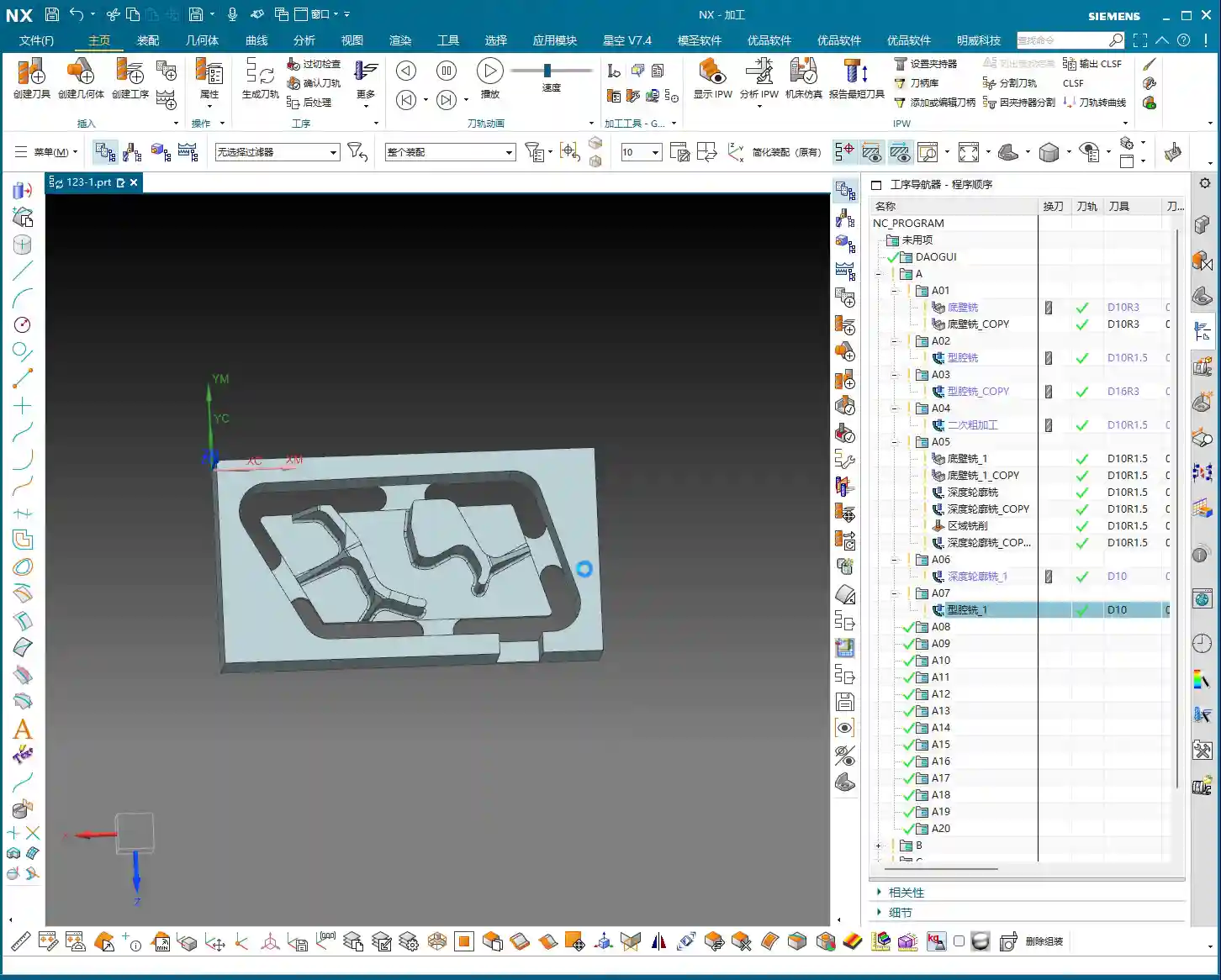
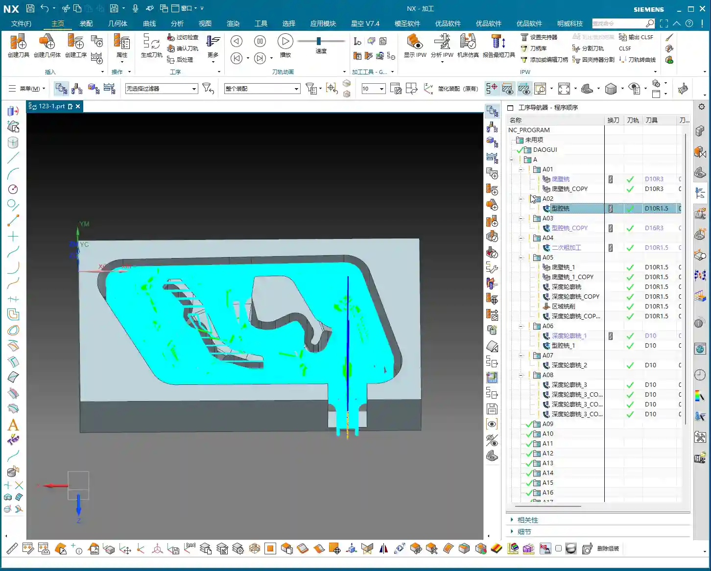
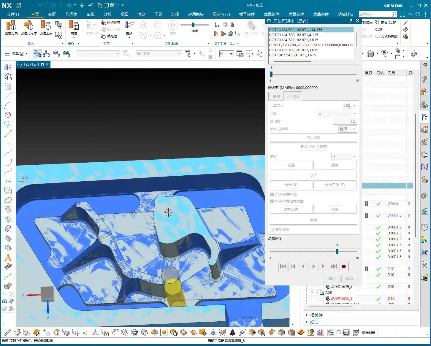
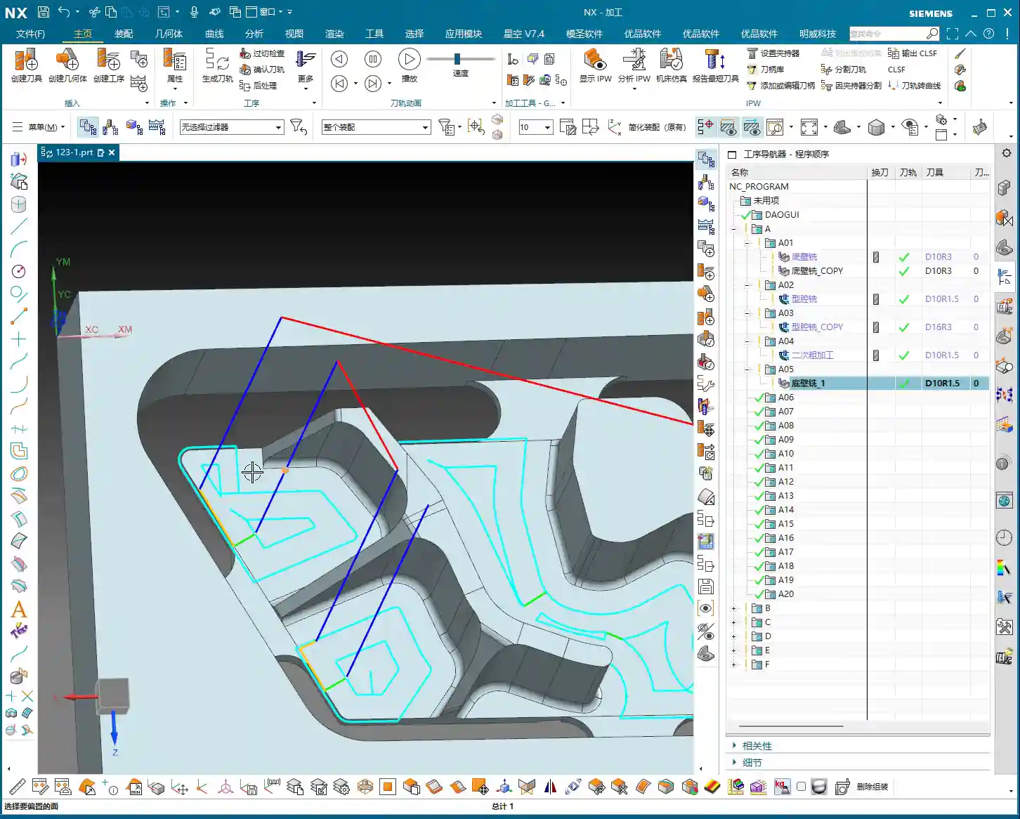
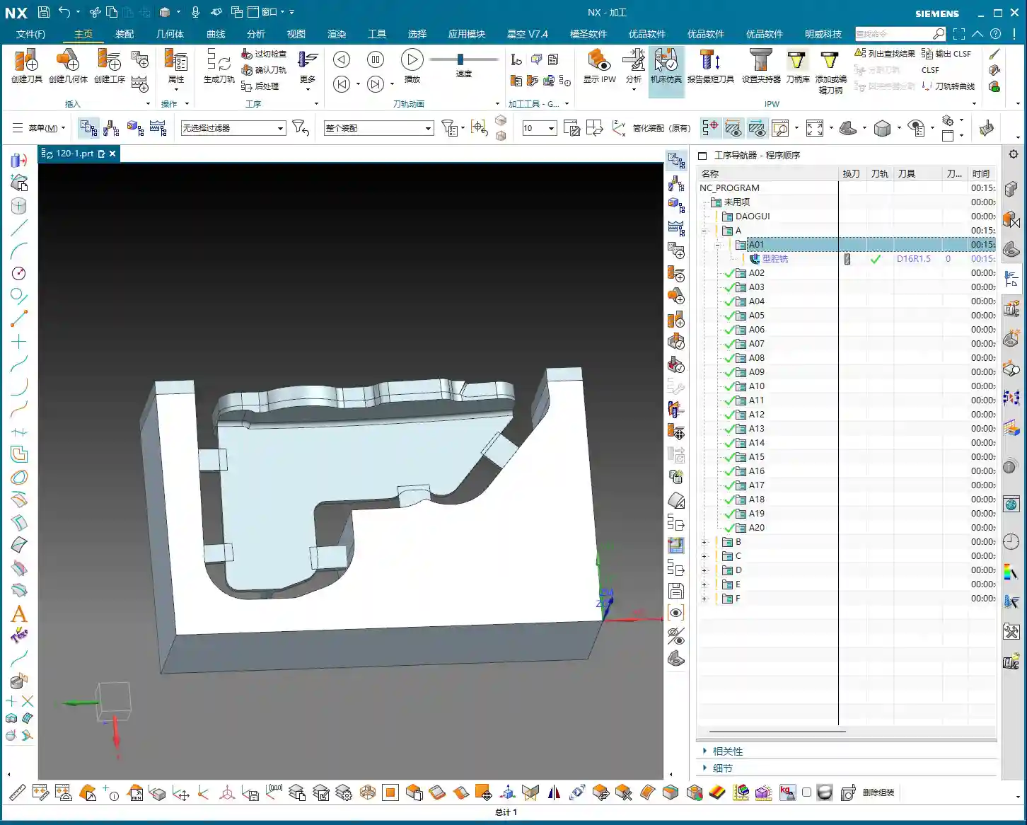
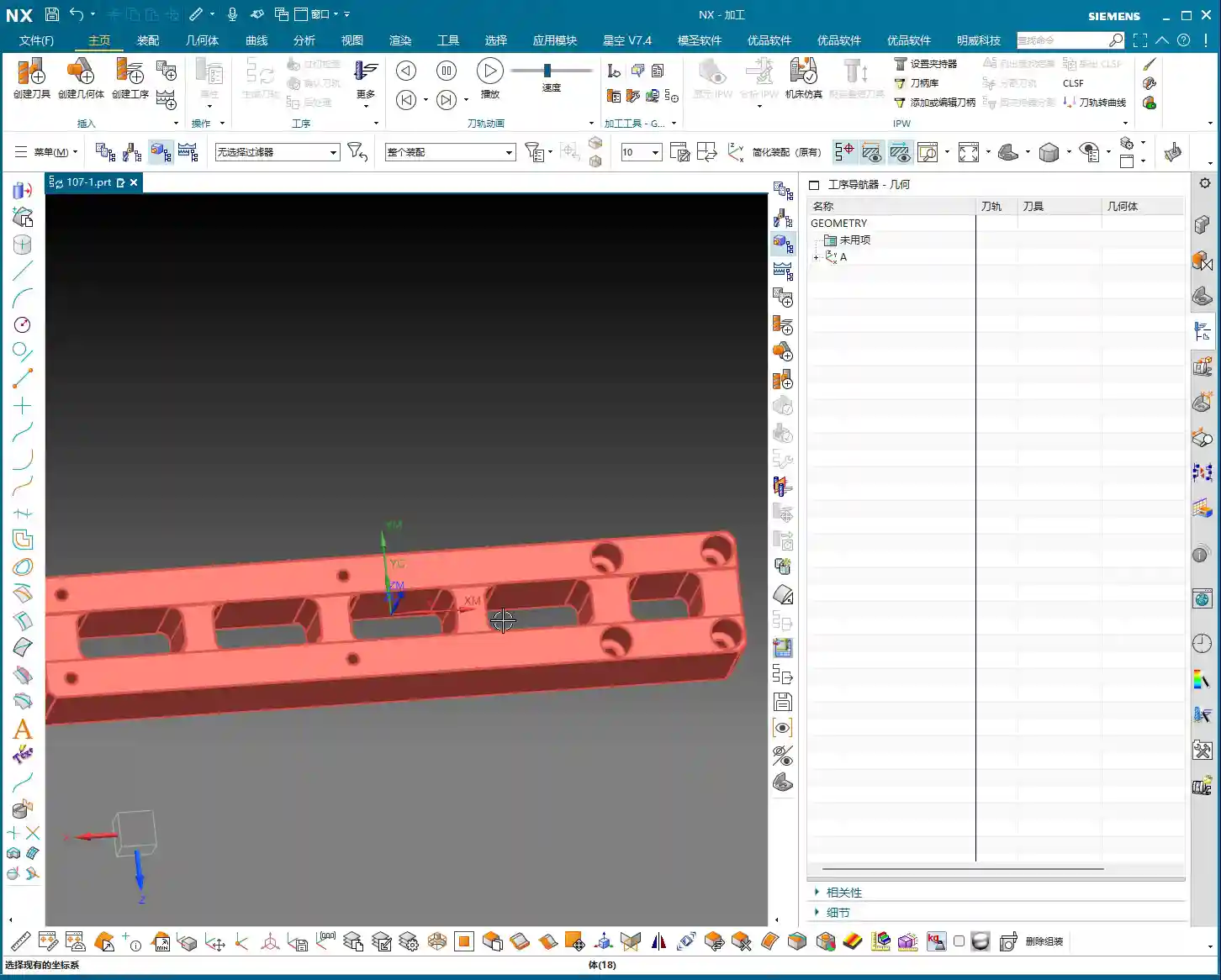
In Siemens NX, first, select all the toolpath programs you want to output an operation sheet for (e.g., A01, A02, A03 for Setup A). Once selected, here’s a good habit: always simulate the toolpaths first to ensure there are no issues and that the fixturing is appropriate.
For a part like this one, Setup A involves machining a single face. So, when clamping, you need to secure the part in a vise, exposing the face to be machined. Simulating it gives you a clear understanding. It also provides the operator with a visual machining preview, building confidence and reducing the chance of errors.
Step Two: Select the ‘Generic Operation Sheet’ Function
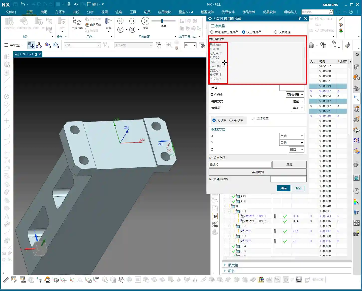
Toolpaths are good, programs are selected. Next, it’s time for the crucial step of outputting the operation sheet. In the Siemens NX menu, find the ‘Generic Operation Sheet’ option. For us, this is usually achieved through the ‘Starry Sky’ plugin. Just click it.
Step Three: Understand Output Options and Path Settings
Once open, you’ll see several output types:
‘Post-Process and Output Operation Sheet’: This means outputting both the G-code (post-processed file) and the operation sheet simultaneously.
‘Output Operation Sheet Only’: This outputs only the operation sheet; we can handle the G-code separately later.
‘Output Post-Process Only’: This outputs only the G-code.
Since we’re focusing on operation sheets today, select ‘Output Operation Sheet Only’. When you do, you’ll notice the ‘Post-Process List’ section is empty. That’s perfectly normal, just ignore it. As for the ‘Tables’ and other options below, those are more detailed settings we’ll cover later; you can safely disregard them for now.
Regarding the output path, many people just stick with the default. But listen up, I, Master Wang, have a personal habit: I typically create a dedicated ‘NC’ folder on my D: drive or another non-system drive, and I put all post-processed files and operation sheets in there. This makes management easier, finding files quicker, and prevents clutter. You might want to adopt this practice.
Step Four: Confirm and Generate the Operation Sheet
Once all previous settings are configured, just click ‘OK’. No need to mess with any other parameters; the operation sheet will be automatically generated and saved to your specified path.
In-Depth Interpretation of Key Information in the Setup A Operation Sheet
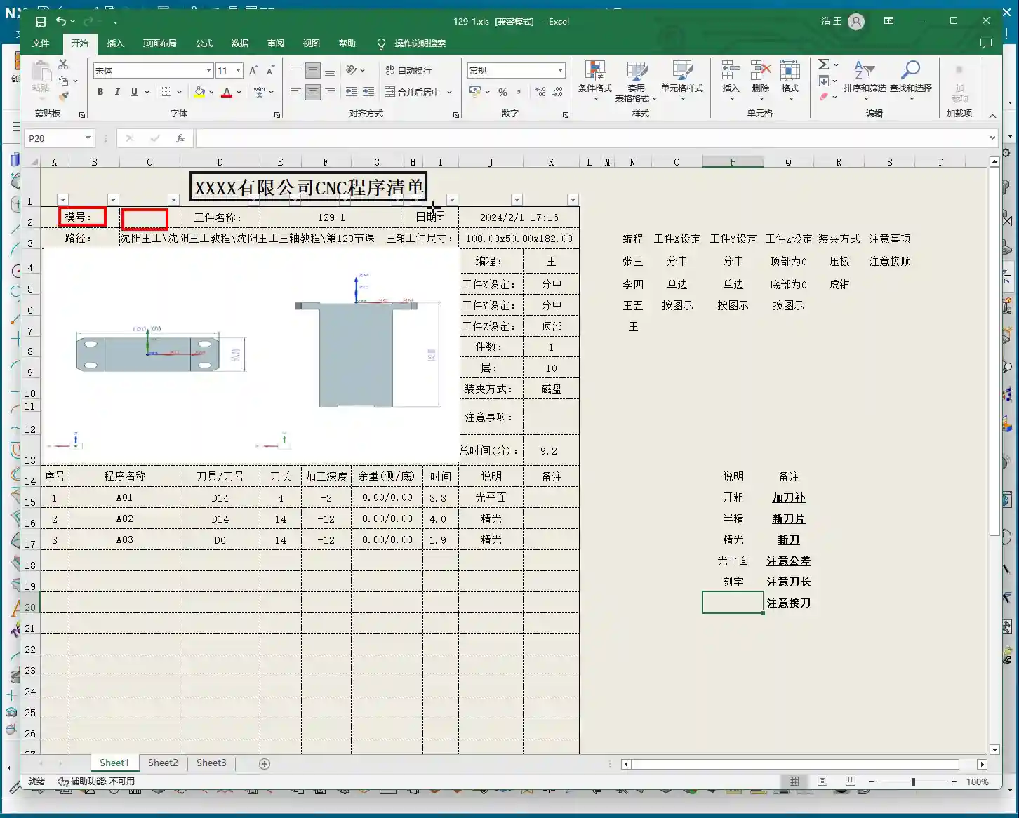
Part Basic Information and Datum Reference
Dimensions: The operation sheet will clearly specify the part’s length, width, and height. For example, our part here is 100mm long, 50mm wide, and 182mm high. These are the final finish cut dimensions, so the operator knows the part’s size at a glance.
Locating Datum: This is critically important! The operation sheet will clearly state the tool offsetting method. For example, here it’s ‘Center X & Y, Top Face Zero’. This tells the operator exactly where the tool offsetting origin is for the X, Y, and Z axes – absolutely no room for error.
Views: The automatically generated XY and XZ views from Siemens NX provide a clear visual of the part’s machining faces and tool offsetting points. When operators see these diagrams, they’ll have a crystal-clear understanding of the features to be machined and the datum locations. Don’t just rely on software simulations; look for the cutting sparks! Drawings are merely aids; the shop floor is where reality happens.
Company and Workpiece Information
Mold/Job Number: This section can be filled according to your company’s specific requirements. If you want it to display the company name or a particular mold number, you can preset it in the operation sheet template. How do you modify the template? I’ve covered that in detail in my previous video tutorials; go check them out yourself – it’s fundamental!
Workpiece Name: For example, Programmer and Date
Prepared By: Here, I’ve put ‘Wang’. You can enter your own name or employee ID. This is also something you modify in the template; set it once, and it will auto-populate thereafter.
Date: The specific date and time the operation sheet was generated, such as
File Path and Dimension Verification
Path: The file path where the operation sheet is stored. While it might be long, the operator only needs to know which lesson’s folder (e.g., ‘Lesson 129’) it’s in to find the corresponding NC file. This helps our shop floor colleagues locate the correct file and prevents loading the wrong program.
Actual Dimensions: Emphasizing again: 100mm long, 50mm wide, and 182mm high. These are the final finish cut dimensions of the part.
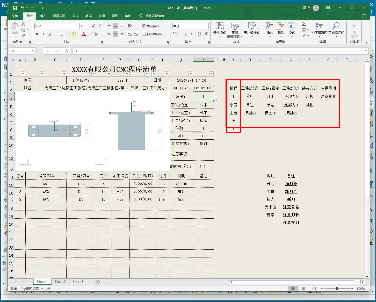
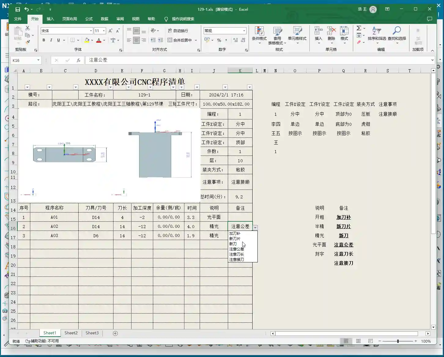
Clamping Method and Precautions
Clamping Method: For example, we’re using a ‘strap clamps’, ‘three-jaw chuck’, Precautions: For instance, Total Machining Time and Sequence Details
Total Time: The combined total machining time for all Setup A programs (A01, A02, A03), for example, Sequence Details: The operation sheet will list each specific program segment:
Program Name: For example, Tool: For instance, Tool Length: Pay close attention here! This refers to the ‘clamped four units’ (e.g., 40mm). It is NOT the overall tool length! This is a common area for Machining Depth: For example, single depth of cut or the depth of a specific feature, not the final machining depth of the entire part. Understand this in conjunction with the actual toolpath.
Description: Such as Remarks: This is a treasure trove! Here, you can jot down all sorts of ‘Pay attention to tolerance’, ‘Change to a new tool’, ‘Mind tool blending’, and so on. These are crucial reminders for the operator to ensure machining quality and efficiency. This section can also be customized in the template; add all your frequently used precautions.
Master Wang’s Wisdom: Practical Tricks for Operation Sheets
Just knowing how to generate an operation sheet isn’t enough; the key is knowing how to use it, how to make it ‘come alive’.
Division of Labor: Post-Processing vs. Operation Sheet: We choose ‘Output Operation Sheet Only’ because post-processing (G-code) requires separate review and verification, while the operation sheet serves as direct instructions for the operator. Keeping them separate clarifies responsibilities and improves efficiency.
The True Meaning of ‘Tool Length’: Remember, the tool length on the operation sheet refers to the fixturing. It’s better to clamp it a bit shorter for more stability than to risk clamping it too long.
Applying ‘Machining Depth’ Flexibly: Don’t mistake the ‘machining depth’ in each program segment as the final depth. It could be the single The Value of the ‘Remarks’ Section: This is where your experience truly shines! Here, you can jot down any ‘frequent air blasts’; if a feature has tight tolerances and requires ‘this tool needs to be replaced halfway through machining’. These are all critical for improving machining quality and reducing scrap.
Path Standardization: My habit of using a dedicated NC folder on the D: drive is all about Template Customization: This is also a big deal! Integrate your company’s commonly used information, standard operation sheet template. This will save a lot of effort every time you generate one and ensure the Master Wang’s Perspective: The ‘Siemens NX + SEO’ One-Two Punch for Industrial Product Promotion
Folks, don’t think I, Master Wang, only know how to write code and sharpen tools. In this day and age, even great products need a good shout-out. Our work on operation sheets isn’t just for production; it’s also excellent material for industrial product promotion.
See, all these detailed processes – Siemens NX modeling, 5-axis simultaneous programming, toolpath optimization, and then today’s topic, operation sheet creation – each step embodies our core technology. Share these practical experiences and technical details through articles, tutorials, and case studies on our official website, industry blogs, or even platforms like Zhihu and Bilibili, accompanied by high-definition Siemens NX screenshots and machining videos. The impact will be completely different!
For example, you could break down the Setup A machining process for a complex part, from modeling to the operation sheet, explaining it step-by-step. Tag it with ‘Siemens NX 5-Axis Programming’, ‘Complex Surface Milling’, ‘Titanium Alloy Machining Process’, ‘Precision Fixture Design’. When potential customers search for these technical solutions online, they’ll find us. Doesn’t that mean we’re directly showcasing our ‘content marketing’, combined with
Summary: Pitfall Avoidance Guide
Operation Sheet ≠ Post-Processed G-code: They have different functions and different purposes; do not confuse them.
Don’t Blindly Trust Times: The machining time on the operation sheet is for reference only; actual conditions may vary due to machine status, operator habits, and other factors.
Utilize the Remarks Section: Don’t underestimate the remarks! It’s the most direct and effective Template Standardization: Customize your operation sheet templates in advance. This will not only improve work efficiency but also ensure information accuracy and consistency, reducing human error.
👤 About the Author: The author is a veteran CNC machining professional with 15 years of industry experience, specializing in UG NX programming. This article is an original work representing personal practical insights.
⚠️ Copyright Notice: Unauthorized reproduction or distribution without prior communication is strictly prohibited.
📝 Key Takeaways: Master Wang explains practical Siemens NX multi-operation part programming, covering the full process from raw stock positioning and process planning to Face Milling, chamfering, pocketing, drilling, and post-processing. The discussion emphasizes Work Coordinate System (WCS) transformation, program optimization, tool selection, and Clamping strategies. He also shares real-world experience on avoiding common pitfalls, helping you boost efficiency, reduce costs, and master practical know-how “you won’t find in textbooks.”
Listen up, young engineers! Today, Master Wang is taking you through multi-operation part programming. Don’t let this example part fool you with its simplicity; it’s a small bird with all its vital organs. We’re not just going to learn how to click around in NX; more importantly, we’ll understand the underlying process logic and machine tool behavior. This is the real expertise gained from hands-on experience in the field – you won’t learn this from any textbook.
Our approach here is to go from raw stock to finished product, with every step carefully calculated. Today’s part is a typical example of multi-sided machining. Programming strategy, Work Coordinate System (WCS) transformations, and smooth operation transitions are all critical in real-world scenarios. Especially for those aiming for complex Surface Milling or 5-axis machining, if your fundamentals aren’t solid, everything else will be built on shaky ground! Siemens NX has a vast number of commands, so we can’t cover everything. We’ll focus on practical techniques that are useful, highly efficient, and cost-effective.
Step One: Overall Planning and Process Decomposition
When you get a new part, don’t rush into drawing or programming. First, you need to visualize its “past and future”: What material is it? What are the precision requirements? How will it be Clamped? What tools will be used? You need to think through all of these. For this part, we plan to complete it in multiple operations with multiple Fixturing setups.
Clarifying the Machining Strategy: Never Fight Unprepared
Listen up, planning comes first. For this part, we’ll use three Work Coordinate Systems (WCS) – A, B, and C – to distinguish different machining faces. The specific steps are roughly as follows:
Operation A (First Face): Machine the front face first, establishing datums for the subsequent flip.
Operation B (Second Face): Flip the part over and machine the back face, again establishing datums.
Operation C (Third Face): Flip it again to machine the holes and pockets on the top or side.
You need to think clearly about each step, otherwise, you’ll be scrambling, leading to scrapped parts or out-of-tolerance dimensions, which will cost you dearly.
Raw Stock Positioning and Clamping Strategy
The Clamping of the raw stock directly impacts machining accuracy and efficiency. For this part, we’ll first fixture one side for Roughing. Once the first side is machined, we then flip the part and re-clamp it. At this point, the new Clamping datum must be selected on the already machined surface from the first side, ensuring accurate datum transfer. While it might seem like just clicking in Siemens NX, on the machine, every detail – fixtures, parallels, clamps – must be meticulously considered.
Step Two: Front Face Machining (Operation A)
This is our first machining face, primarily involving Face Milling, chamfering, and pocket Roughing. Don’t underestimate Face Milling; the flatness and surface finish directly influence the datums for subsequent operations.
Face Milling and Chamfering
First, we’ll use a face mill to flatten the entire surface. The Depth of Cut (DOC) can be a bit larger, for example, 2mm, to get it done in one go. Remember, when programming, your entry and exit paths must be smooth; avoid sharp, right-angle turns, as that can lead to heavy tool engagement, which is bad for both the tool and the machine.
Next is chamfering. This may seem like a minor detail, but its function is significant: it eliminates sharp edges, protects operators, and prevents part damage during handling. We’ll use depth milling, select these four corners, and set the Depth of Cut (DOC) to 50% of the tool diameter. That’s a solid approach.
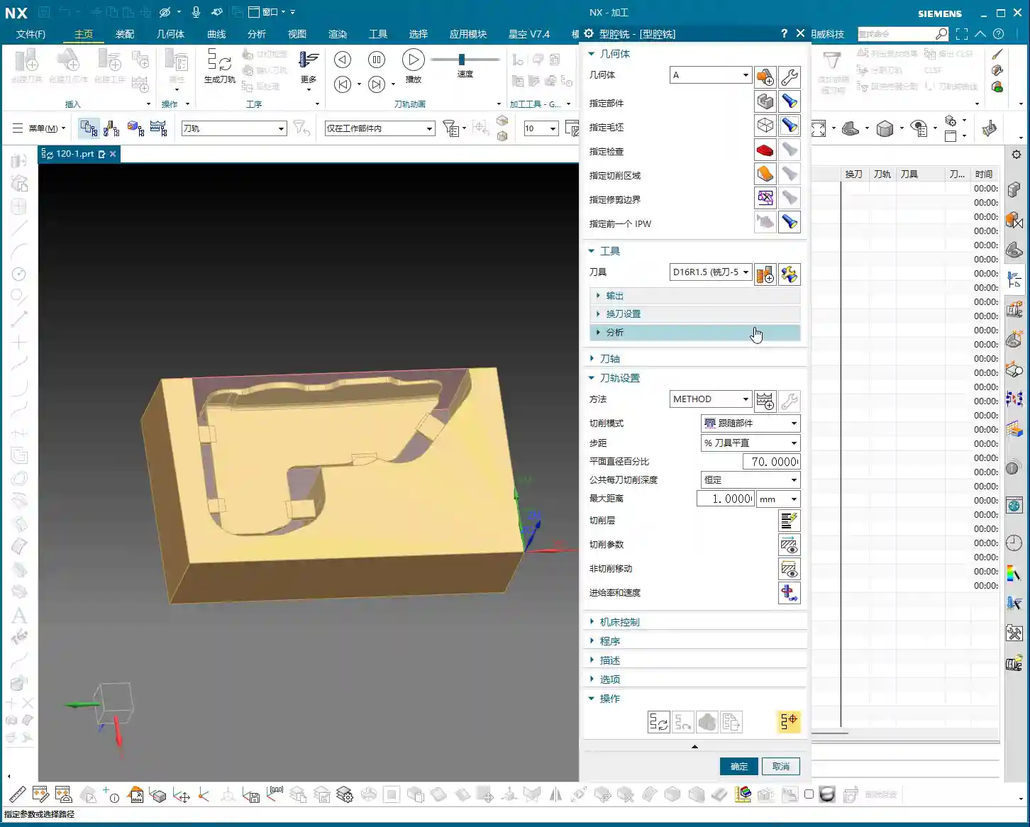
Pocket (Cavity) Roughing
Next is the Roughing of the internal pocket. For this, we’ll use a pocket milling operation. As for tooling, start with a larger tool to clear most of the material. The Depth of Cut (DOC) and feed rates must be determined by the material properties. For example, common aluminum can be machined faster, but titanium alloys and high-temperature nickel-based alloys require a more cautious approach to ensure chip evacuation and tool life.
Master Wang’s Pro Tip: Don’t always aim for a single-pass solution; separating Roughing from Finishing is the golden rule. Roughing prioritizes efficiency, leaving sufficient material allowance; Finishing pass prioritizes accuracy and surface finish, so the cuts must be stable and slow.
Step Three: Back Face Machining (Operation B)
Once the first face is done, we’re ready for flip-over machining. At this stage, Work Coordinate System (WCS) transformation is paramount; get it wrong, and all your previous efforts will be wasted.
Coordinate System Transformation: Flipping is Key
Listen up, creating a new WCS (Coordinate System B) typically involves reversing the Z-axis direction and redefining the XY plane. The easiest method is to use an already machined feature as a reference for your new Work Coordinate System (WCS). For example, the face you just Face Milled on the first side becomes your Clamping datum for the second side. In Siemens NX, as long as you select the correct datum, the system will automatically help you with positioning, saving you time and effort.
Leveraging Copy-Paste: Efficiency is King
In Siemens NX programming, especially for symmetrical or similar machining operations, copy-paste operations are a powerful tool for boosting efficiency. You can directly copy the Face Milling and chamfering operations from Operation A, then simply modify the Work Coordinate System (WCS) and machining region. This significantly reduces repetitive work and ensures operational consistency.
Programming Tip: After copying an operation, don’t forget to check all parameters, especially clearance planes, lead-in/lead-out strategies, and most importantly, material allowance settings – these are common areas for errors.
Step Four: Remaining Feature Machining (Operation C)
After the first two sides are Roughed, we need to address the part’s holes and Finishing passes. This involves another new Fixturing setup and Work Coordinate System (WCS), typically for machining features on the top or side.
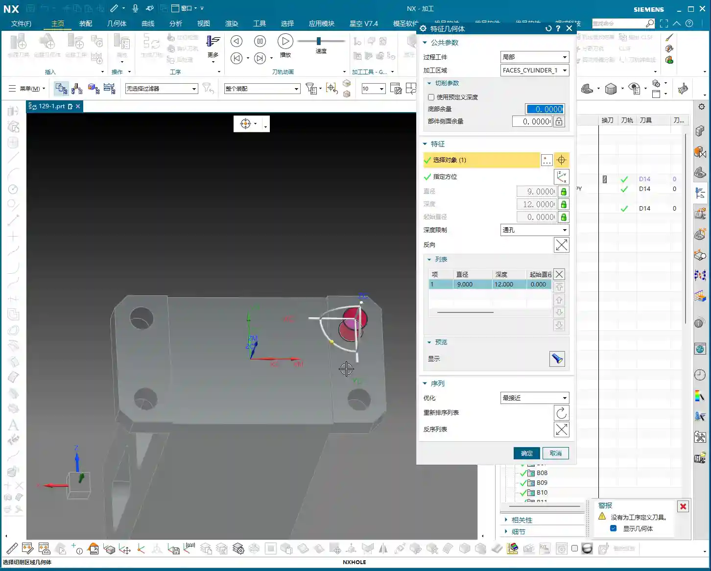
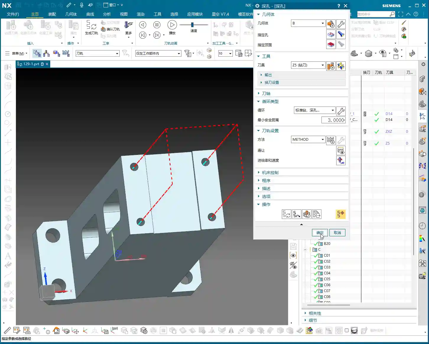
Hole Machining: Spot Drilling and Deep Hole Drilling
For hole machining, especially for high-precision holes, it’s not as simple as just plunging a drill bit.
Spot Drilling (Center Drilling): First, use a spot drill to establish the center point, preventing the drill from walking. This is fundamental.
Deep Hole Drilling: For deep holes, you must use a deep hole drill and set up peck drilling or chip breaking cycles to prevent chip packing and tool burning. Don’t just rely on software simulation; observe the cutting sparks and chip condition – that’s the real feedback.
For our 5mm diameter hole, we’ll first spot drill for positioning, then use an appropriate drill bit to drill to full depth.
Pocket Finishing and Helical Milling
For pocket Finishing passes, helical milling is an excellent choice. It allows the tool to engage smoothly, avoiding impact, and is particularly well-suited for difficult-to-machine materials like titanium alloys and high-temperature nickel-based alloys. Helical entry allows for precise finishing of the side walls and bottom, step by step.
Master Wang’s Pro Tip: For Finishing passes, the tool overhang must be short, and rigidity must be excellent. Feed rates and spindle speeds need to be matched, and coolant flow must be ample; otherwise, you’ll easily generate chatter marks, compromising surface quality. For this pocket, we’ll set the bottom stock allowance to 0, leave a 0.05mm allowance on the side walls for the Finishing pass, then use a finishing end mill for a single finish cut to depth.
Step Five: Program Output and Post-Processing
Don’t assume everything is done once all the operations are programmed. The most critical step is converting the virtual toolpaths in Siemens NX into the language the machine tool understands – G-code. This requires a setup sheet and post-processing.
The Value of Setup Sheets and Post-Processing
A setup sheet is your operational manual, clearly detailing the tooling, parameters, Fixturing, and precautions for each step. It’s the machine operator’s “bible.”
Post-processing, now that’s a specialized skill. It translates Siemens NX’s internal data into G-code and M-code that specific machine tools (such as FANUC, SIEMENS, etc.) can recognize. For me, Master Wang, modifying post-processors is routine. The goal is to optimize code structure, reduce air cuts, enhance machining efficiency, and even correct some inherent machine tool errors through post-processing (at the ±0.005mm level).
Marketing Perspective: A clear, accurate, and efficient setup sheet and G-code not only guarantee product quality but also represent the strength of our manufacturing facility. In industrial SEO, this is the best calling card to showcase our “professional, precision, and high efficiency” to clients, helping your product keywords rank high on search engine home pages!
Toolpath Optimization: More Than Just Software
Software simulations might show beautiful toolpaths, but real-world machine performance is what truly matters. Too many air cuts? Uneven cutting loads? These issues require careful adjustment within Siemens NX, or optimization at the post-processor level. For instance, using Siemens NX’s “Optimize Toolpath” function can automatically plan the shortest path, reducing non-cutting movements – every second saved is money!
Summary: Pitfall Avoidance Guide
Alright, we’ve walked through this multi-operation part programming example from start to finish today. Finally, Master Wang has a few more reminders for you – these are practical experiences you won’t learn from books, so commit them to memory:
Fixturing is fundamental, datums are critical: For multi-operation machining, ensure you select the correct datum surface for each flip and Clamping setup; otherwise, dimensional errors are guaranteed.
WCS management must be rigorous: Clearly define A, B, and C Work Coordinate Systems (WCS) and ensure they correspond precisely in the program to prevent operator confusion.
Tool selection must be appropriate, and cutting parameters must match: Don’t try to use one tool for everything, and never input random parameters. Material, tool, and machine tool – these three must be properly matched.
Separate Roughing and Finishing, leave room for error: Leave sufficient stock for Roughing, then perform the Finishing pass. This is the ironclad rule for ensuring accuracy and surface finish.
Never be careless with post-processing and setup sheets: These are your bridge of communication with the machine tool and the operator. The code must be concise, and instructions detailed; otherwise, they are potential hazards.
Observe cutting sparks, listen to machine sounds: No matter how good the software simulation is, it cannot replace on-site experience. The color of cutting sparks, the shape of chips, and the sound of the machine’s load are all “signal lights” for judging the machining status.
Remember, programming isn’t “magic”; it’s a combination of science and accumulated experience. Practice more, think more, and summarize more, and you will truly become a master craftsman in machining!
“`
👤 About the Author: The author is a veteran CNC machining professional with 15 years of industry experience, specializing in UG NX programming. This article is an original work representing personal practical insights.
⚠️ Copyright Notice: Unauthorized reproduction or distribution without prior communication is strictly prohibited.
📝 Key Takeaways: Master Wang’s personal secrets for Siemens NX Side Milling Head programming: The core is a “two-step” strategy. A detailed explanation of Tool Axis and Clearance Plane settings to avoid chatter and unnecessary air cuts. From Coordinate System setup to Roughing and Finishing, a step-by-step guide on how to efficiently and precisely machine complex groove parts. Move beyond pure theory and address real production challenges!
Hello everyone, I’m Master Wang. Last lesson, we thoroughly explored how to machine that workpiece below. This time, let’s dive into something more advanced – discussing 4-axis machining, specifically Side Milling Head programming.
Introduction: The ‘Two Key Skills’ of Side Milling Head Machining
Listen up, we’ll use this feature with a groove and specific geometry as an example, because it connects all the core technical points of the Side Milling Head. Don’t underestimate a simple groove; there’s a lot of knowledge involved.
Coordinate System Setup: The Absolute Foundation
Before starting any work, the first step is always to correctly set up the Work Coordinate System (WCS). This is a fundamental rule in NX programming and the lifeblood of our machining operations. If your WCS is incorrect, everything else will be pointless.
“Once you’re in the manufacturing module, make sure the coordinate system is set. Typically, we place it above the part’s datum face (bottom face), with the machining surface as the zero point. The Z-axis zero point is the part surface itself; this ensures dimensional accuracy. Don’t slip up! I just accidentally clicked into the properties, wasting time!”
The XYZ axis directions, especially the Z-axis, must align with your design intent and actual fixturing. This is fundamental and cannot be overlooked.
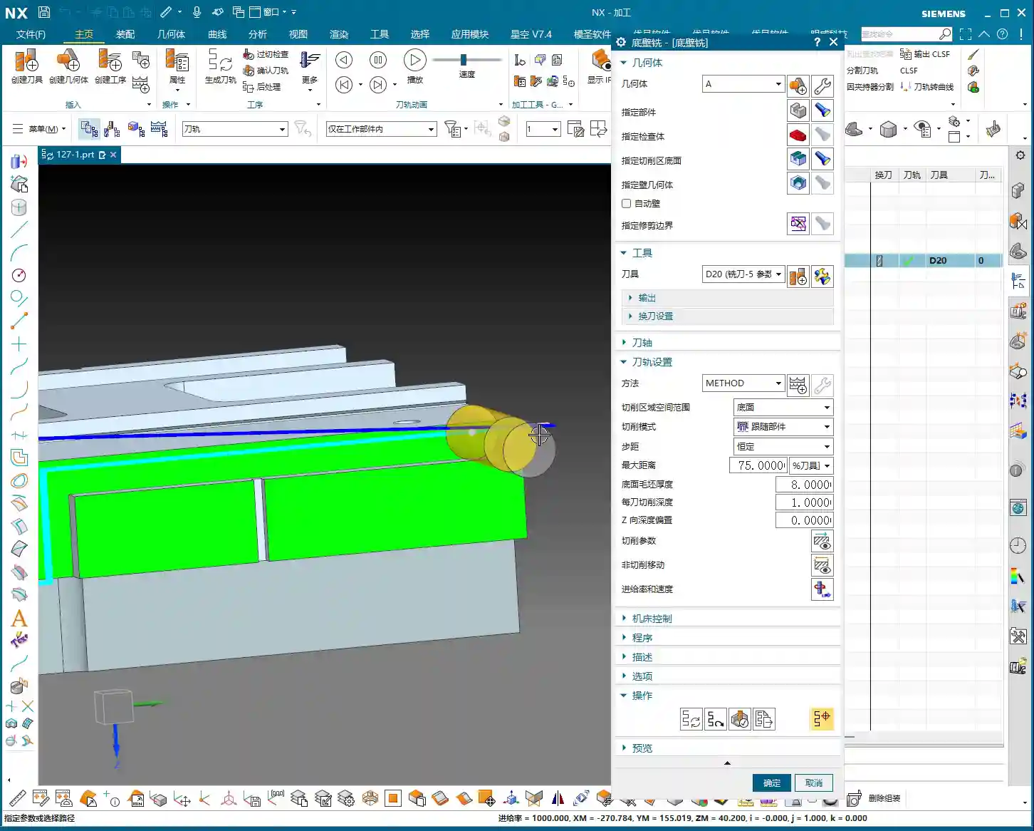
Practical Exercise One: Roughing Techniques for Floor and Wall Milling
Programming for a Side Milling Head isn’t vastly different from our usual 3-axis programming approach. The main distinctions lie in post-processing and the setup of a few specific parameters. Don’t rush, let’s take it step by step.
Floor and Wall Milling Operation and Initial Toolpath Generation
“Insert an operation; we’ll start with Floor and Wall Milling to rough out this groove feature. Let’s assume the bottom surface has already been milled, and we’re starting from the side. We’ll also assume the blank surface is flat to skip some initial preparation details.”
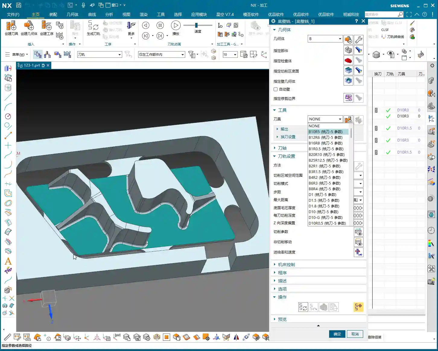
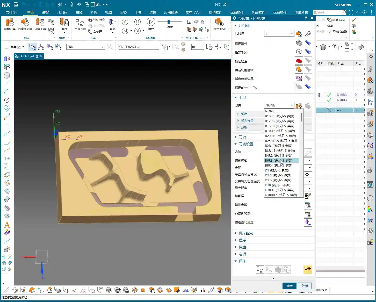
Let’s measure the depth of this groove first; it’s 8 mm. Therefore, select this side face for material removal and set the machining depth accordingly. For the tool, let’s just pick one for now, say a D10 end mill. Today’s focus is how to program for the Side Milling Head; we’ll delve into tool selection later.
“Just click generate and take a look. See that? The toolpath goes back and forth; it’s inefficient and results in a poor surface finish. This is exactly what we need to optimize!” While this back-and-forth ‘zigzag’ cutting might be acceptable in some situations, for Side Milling Head operations, especially for grooves, one-way cutting (climb or conventional milling) is the superior approach.
There’s another issue: once the program generates, observe the approach and retract moves. They lack smooth entry and exit. This is a major no-no in actual machining; directly plunging into the material can lead to chatter or even tool breakage, and it degrades the workpiece surface quality!
Core Secret: The ‘Two-Step’ Strategy for Side Milling Head Programming
To program effectively for a Side Milling Head in NX, just remember these two tricks—they’re practical know-how you won’t find in textbooks.
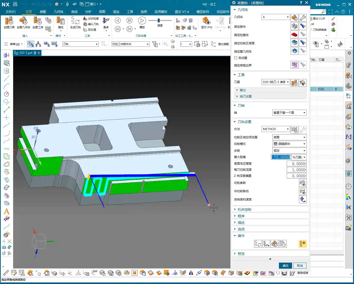
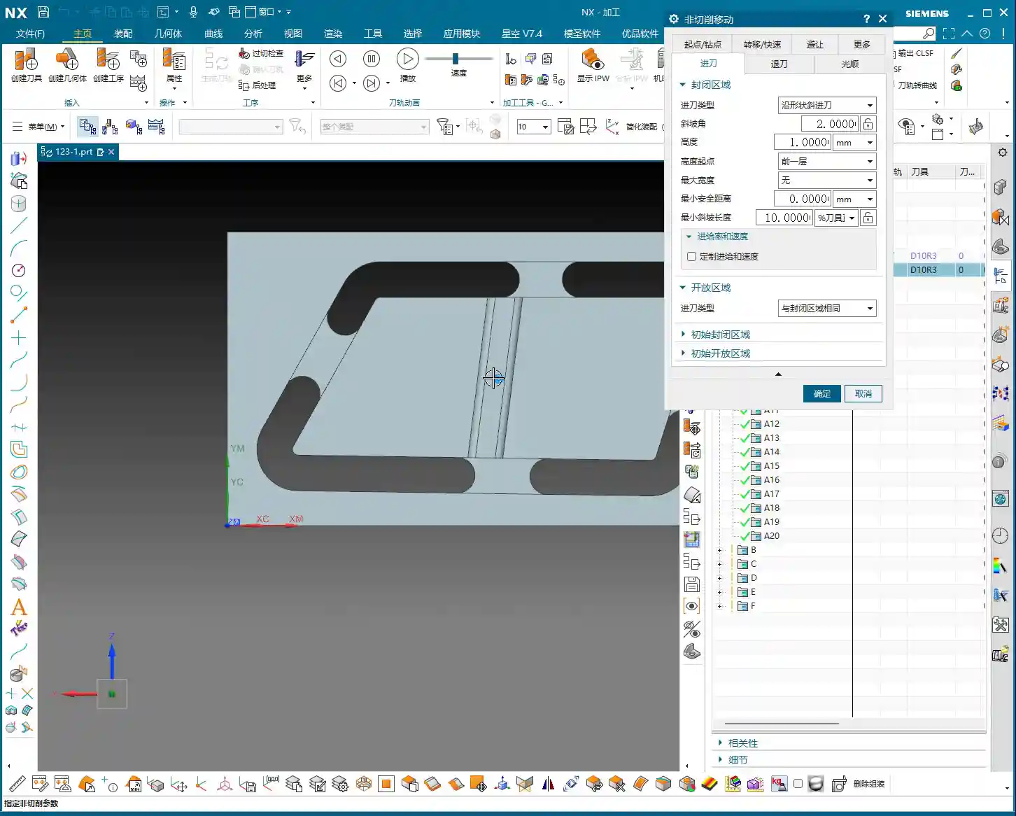
Trick One: The Key to Clearance Plane Setup
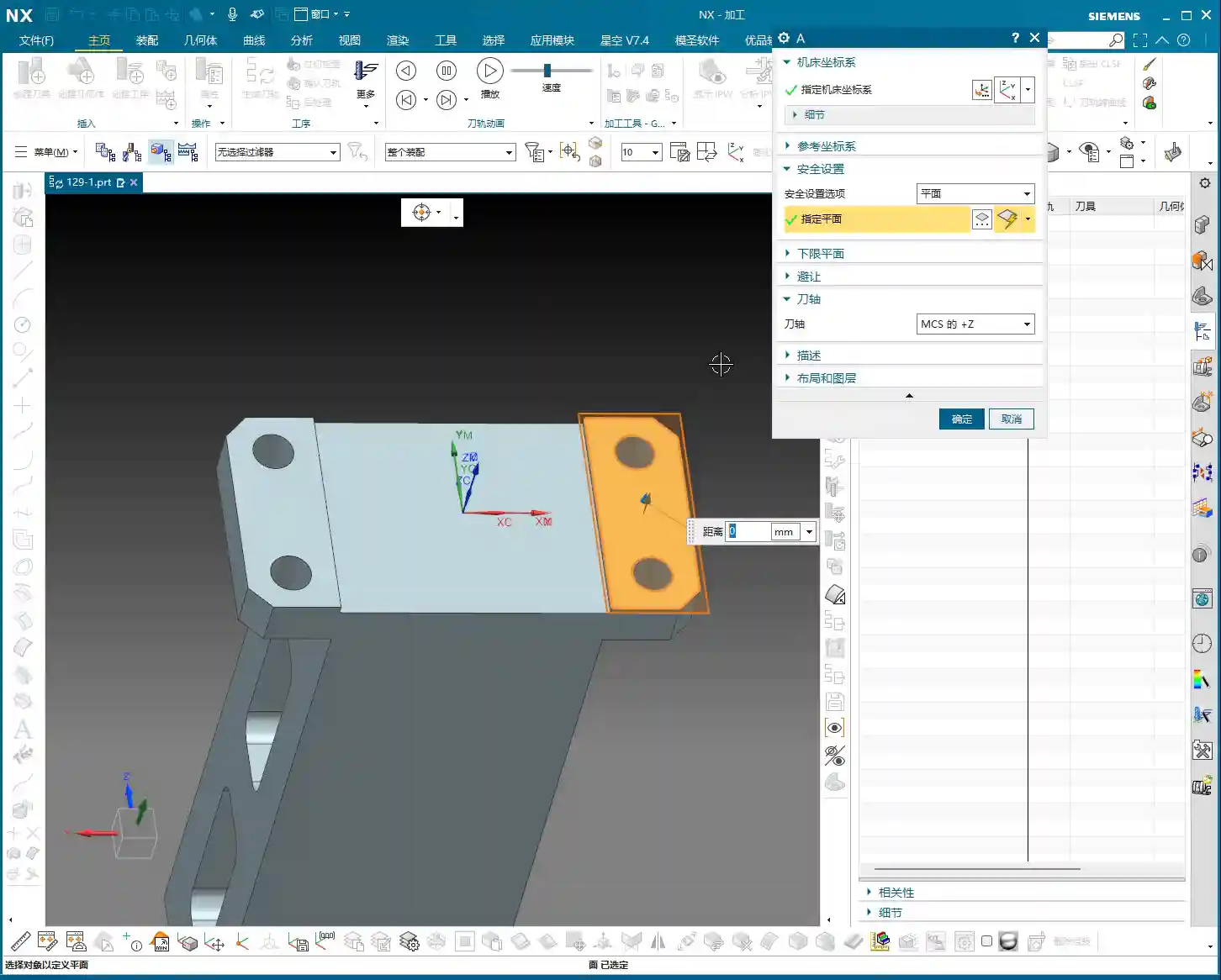
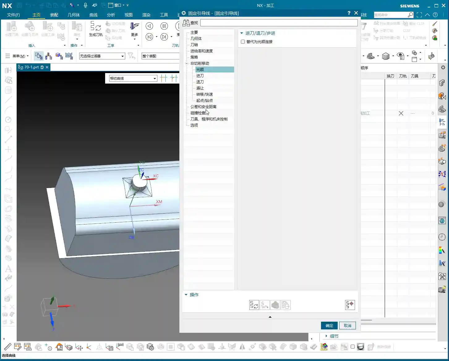
“In our usual 3-axis machining, the clearance plane is always above the workpiece to prevent collisions. But with a Side Milling Head? It’s working from the side! Therefore, the Clearance Plane must change accordingly.”
Go into the “Non-Cutting Moves” options and find “Clearance Settings”. Change the original “Automatic” or “Distance” setting to “Plane”. Then, here’s the crucial part: designate your clearance plane as the side face of the machining surface, and adjust the offset direction and distance. This way, during rapid moves, the tool will safely retract from the side instead of lifting high up and then coming back down, which both improves efficiency and prevents collision risks.
“For operations like Floor and Wall Milling, just adjusting the clearance plane is enough, as its tool axis is by default perpendicular to the bottom face. However, for other operations like Planar Profile and Depth Profile, you’ll need to use the second trick.”
Trick Two: Precise Control of Tool Axis Direction
This is the essence of Side Milling Head programming! “If the Tool Axis direction is incorrect, the program simply won’t generate, or it will behave erratically if it does. Don’t just rely on software simulations; observe the cutting sparks!”
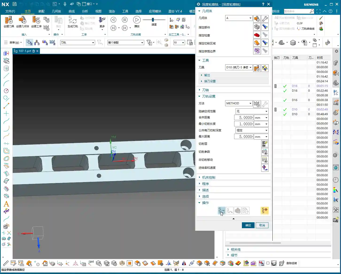
For Side Milling Head operations other than Floor and Wall Milling, the tool axis might still default to the Z-axis direction, which is incorrect. We need to go into the “Tool Axis” settings:
Select “Specify Vector”.
Then choose “Fixed” or “Automatic Detection”. The most reliable method is to directly select the specific side face you intend to machine.
The software will automatically adjust the tool axis direction to be perpendicular to the selected side face.
“Once this is changed, the tool will know which direction to cut. Combined with linear approach and retract moves, for instance, using 60% of the tool diameter as the entry length, the cutting process becomes much smoother. This prevents direct tool impact on the workpiece, significantly extends tool life, and improves machining quality.”
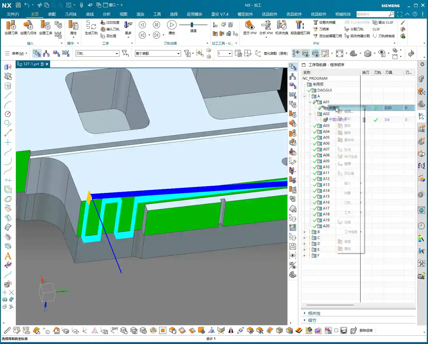
Practical Exercise Two: Tool Axis Adjustment for Planar Profile and Depth Profile Milling
Alright, let’s switch locations and demonstrate again. This time, we’ll use Planar Profile and Depth Profile Milling, specifically for side walls.
Planar Profile Milling Case Study: Tool Axis Correction and Parameter Optimization
“Let’s measure this groove width; it’s 4 mm. So, we’ll directly use a 4 mm tool for roughing.”
Create a new “Planar Profile” operation, select the machining boundaries, bottom face, and so on. Tool D4, generate the program directly… “See? Still no good! It’s warning again that the ‘tool axis cannot be perpendicular to the bottom face.’ This is exactly what we discussed earlier—we need to change the Tool Axis!”
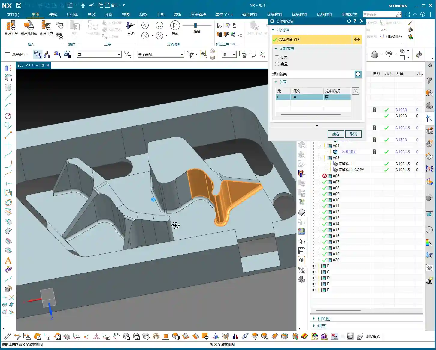
Open the “Tool Axis” settings, change it to “Specify Vector”, then select “Automatic Detection”, and finally, the crucial step: click on the side wall plane you intend to machine! “This way, the tool understands its direction is towards the side.”
Once the tool axis is corrected, the program can generate smoothly. Don’t forget to optimize the cutting parameters:
Stepdown: 0.2 mm.
Cutting Method: Mixed Cut.
Stock: 0 (if this is a Finishing pass).
Approach/Retract: Linear approach, 60% of tool diameter, Retract is 0.
Finally, don’t forget to also change the Clearance Plane to the side. This way, your entire Side Milling Head roughing program will be solid. If you need a Finishing pass, simply copy and paste the program, set the stock to zero, and recalculate; you’ll get it done quickly.
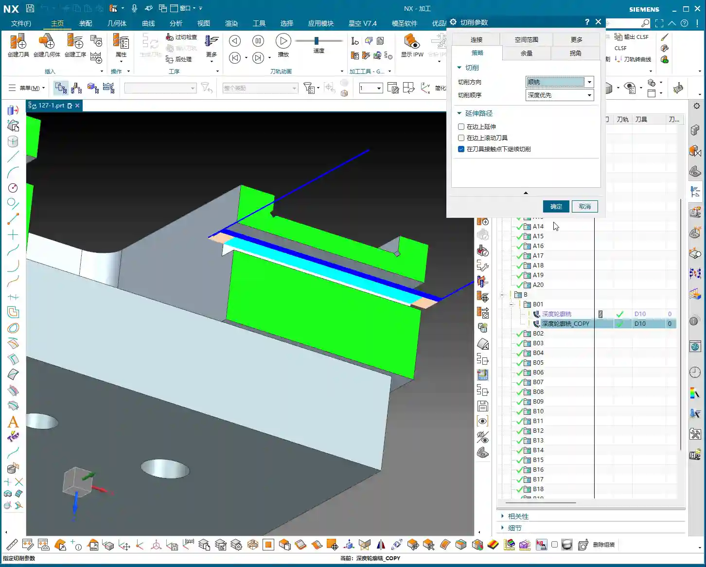
Depth Profile Milling Case Study: Non-Standard Tools and Approach/Retract Optimization
Let’s look at another example with Depth Profile Milling. “I measured this area, and it has a dimension of 10.1 mm. This isn’t a standard tool size! We can only use a D10 tool, leaving a small amount of stock, and then follow up with a Finishing pass.” This is a practical situation in production—you can’t just customize a tool for every non-standard dimension, can you? The cost won’t allow it!
For the operation, select “Depth Profile Milling” and for the cutting method, choose “Center” (which makes the tool center follow the boundary). With the initial settings, the tool axis is still Z-directional, and the program won’t generate. “It’s the Tool Axis problem again! Same old issue.”
Just like before, change the tool axis to “Specify Vector”, select “Automatic Detection”, and then click on the side wall plane. The program will then generate normally.
Then, for optimization:
Cutting Method: Mixed Cut, for a more even toolpath.
Approach/Retract: Linear, 60% of tool diameter, Retract is 0.
Stock: 0.05 mm (to leave material for Finishing pass).
Finally, check and set the Clearance Plane, ensuring it’s on the side. With that, your Depth Profile Milling program is also sorted.
Summary: Pitfall Avoidance Guide
Alright folks, listen up! The core of Side Milling Head programming boils down to these two points. Master them, and you’ll save a lot of detours and prevent many tool crashes:
Tool Axis Direction: This is the soul of Side Milling Head programming. Except for a few operations like Floor and Wall Milling where the tool axis is automatically determined, for any other side machining operation, you must manually specify the tool axis direction. Select “Specify Vector,” then click on the side face you are actually machining, so the tool cuts perpendicular to that face. This is crucial for preventing the tool from “crashing into the wall”!
Clearance Plane: A Side Milling Head operates from the side, so its clearance plane should also be on the side. In “Non-Cutting Moves,” ensure you change the clearance settings to “Plane” and designate a side face parallel to the machining surface as the clearance plane. This allows the tool to safely approach and retract, avoiding unnecessary lifts and air cuts, thereby boosting overall machining efficiency.
Approach/Retract Settings: To ensure stable cutting and extend tool life, always set the approach and retract moves to linear or arc transitions. Also, set an appropriate entry distance (e.g., 60% of the tool diameter) to prevent the tool from directly impacting the workpiece.
Handling Non-Standard Dimensions: When encountering non-standard dimensions like 10.1 mm, don’t think about customizing a tool. Prioritize using a nearby standard tool (e.g., D10), and resolve the issue by leaving stock and performing a secondary Finishing pass. This is the most cost-effective approach.
Remember these practical tips, and you’ll get fewer reprimands and produce more in the workshop! Don’t just rely on software simulations; go to the machine, observe the cutting sparks, and listen to the cutting sounds – that’s where the real skill lies!
👤 About the Author: The author is a veteran CNC machining professional with 15 years of industry experience, specializing in UG NX programming. This article is an original work representing personal practical insights.
⚠️ Copyright Notice: Unauthorized reproduction or distribution without prior communication is strictly prohibited.
NX Complex Rib Programming: A Practical Deep Dive into a Three-Stage Process
Alright, Listen Up, Lads! Master Wang Teaches You Three Tricks to Ace Rib Machining
Today, we’re not talking theory; we’re getting straight to the practical insights. All that theory you learned in school often leaves you stumped on the shop floor, especially with parts like these ribs that demand both strength and precision. Don’t worry. Today, Master Wang will walk you through this case study, showing you how to program efficient and precise toolpaths using Siemens NX. Remember, machining isn’t just theory; it’s about watching the cutting sparks and listening to the machine!
Don’t let the simple structure of these ribs fool you; they’re often the backbone of a part, demanding high strength and precision. Especially those small fillets and chamfers at the connections—mishandle them, and you’ll either compromise assembly or create stress concentrations, leading to immediate scrap. That’s why Master Wang has put together a “Three-Stage” programming method that’s guaranteed to be effective and immediately applicable!
Stage One: Rib Side Wall Roughing / Semi-Finishing – “Aggressive Yet Controlled, Step by Step”
This is the first, and most crucial, step. The side walls of the rib are often the primary load-bearing surfaces and must be smooth and flat. We need to start with a larger tool to Contour Mill out the basic shape.
Core Operation: Cleverly Use Surface Milling, Avoid Ball End Mill Pitfalls
Listen up, here we’re using “Surface Milling”. Why Surface Milling? Because it’s highly adaptable to complex surfaces, creating smoother toolpaths and uniform cutting forces. Some novices see a sloped surface and immediately think of using a ball end mill – a huge mistake! When machining side walls with a ball end mill, the cutting action occurs at the tool’s bottom, leading to low cutting efficiency and prone to Chatter. Especially when the bottom fillet hasn’t been cleared yet, a ball end mill simply can’t reach, failing to “Contour Mill to the bottom surface.”
Tool Selection: I typically choose a D12R1.5 (diameter 12mm, 1.5mm corner radius) flat end mill with a radius. Don’t underestimate this corner radius; it significantly boosts tool strength, preventing chipping at the tip, and also simplifies Corner Cleanup in subsequent operations.
Infeed and Cutting Parameters:
Depth of Cut: If it’s aluminum, you can go with a 0.15mm Stepdown per pass. Don’t get greedy; we’re not chasing speed, we’re laying the groundwork for the Finishing pass.
Cutting Pattern: Use “Zigzag” to reduce retracts and improve efficiency.
Stock Allowance Control: Leave 0.2mm on the side walls and 0.3mm on the bottom surface. These allowances are for subsequent Finishing passes and Corner Cleanup; don’t machine them all off in one go.
Boundary Selection: Precisely select the side wall surfaces to be machined. As for those small fillets, leave them for now; we’ll tackle them in Stage Two.
Master Wang’s Tip: Software simulations look great, but ultimately, it comes down to the cutting sparks and sound from the machine. If the sound is dull, it indicates excessive cutting force, possibly due to too fast a feed rate or too large a Depth of Cut – you need to adjust it! Excessive sparks suggest tool wear, which also needs attention.
Stage Two: Cavity Roughing and Local Finishing – “Progressive Refinement, Fine Detailing”
Stage One covered the main outline of the rib. Now it’s time to tackle the hidden cavities and fillets, which are critical for precision and surface quality.
Core Operation: Utilize Deep Contour Milling and Cavity Milling Concurrently for Thorough Fillet Cleanup
This stage consists of two parts: roughing first, then finishing, with targeted strategies.
Cavity Roughing (Main Area):
Operation Type: We’ll use “Cavity Milling for Roughing”. For material removal in the areas beneath the rib or the main body, cavity milling offers the highest efficiency.
Tool Selection: You can still use the previous D12R1.5 tool, or switch to a larger diameter tool depending on the cavity size.
Cutting Parameters: Use a 0.5mm Depth of Cut per pass, a side wall allowance of 0.1mm, and set the bottom allowance to 0 this time (as it’s managed internally by the cutting levels), ensuring thorough roughing without overcutting.
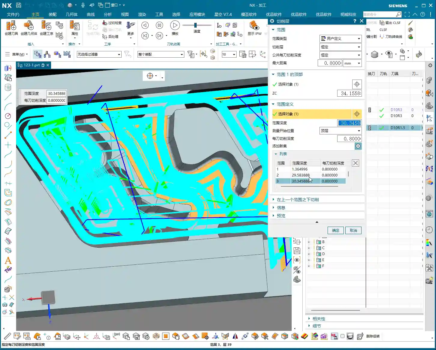
Depth Control: Start from the top surface of the rib and mill down to the final bottom surface. Remember to leave a 0.1mm machining allowance to prevent milling into the workholding table and to provide room for the Finishing pass.
Local Fillet Finishing (Corner Cleanup):
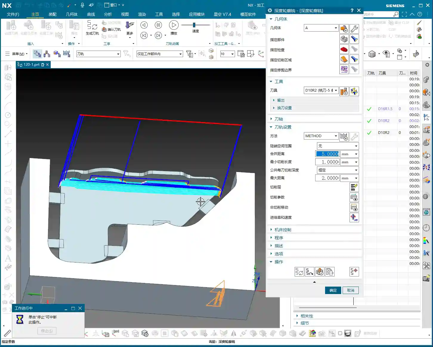
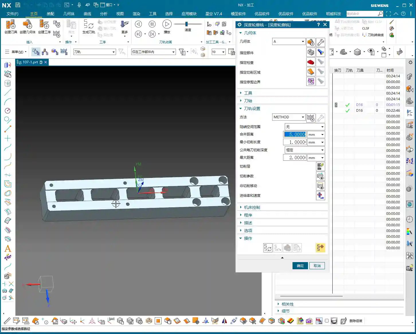
Operation Type: The core operation is “Deep Contour Milling”, specifically for Corner Cleanup. It performs multi-level cutting along the part’s contour, making it ideal for internal radii.
Tool Selection: Switch to a smaller ball-nose end mill, for instance, a D6R0.5 or D4R0.2. Determine this based on the minimum fillet radius of the rib; the tool diameter must be less than or equal to the minimum fillet diameter.
Cutting Parameters: Use a 0.5mm Depth of Cut to ensure stable cutting. Most importantly, precisely control the start and end surfaces, beginning from the bottom surface of the rib, adding the fillet radius as the start height, and milling to the target height.
Allowance: Set both side wall and bottom allowances to 0; this pass is about milling it precisely to size, ensuring thorough Corner Cleanup.
Master Wang’s Tip: When using Deep Contour Milling in complex areas, you might sometimes encounter “Chatter” or “tool skipping” phenomena. If this happens, try reducing the feed rate or adjusting the cutting strategy, for example, from “Conventional” to “Climb Milling.” Don’t be afraid to go slow; stability and precision are paramount.
Stage Three: Contour Finishing and Final Cut-Off – “A Single Pass for Perfection, The Grand Finale”
The first two stages have largely taken care of the rib’s forms and internal features. This final stage is about giving the part its “outer finish” and cleanly “liberating” it from the raw stock.
Core Operation: Smooth Side Walls, Precise Cut-Off, Leave a “Tab”
This step is crucial for the final surface quality and the integrity of the part; don’t mess it up.
Rib Side Wall Finishing Pass (Smooth Side Walls):
Operation Type: Continue using “Deep Contour Milling”, as it allows for a precise Finishing pass across the entire side wall, ensuring surface finish.
Tool Selection: We’ll use a D10R0.5 ball-nose end mill to ensure the required surface roughness.
Cutting Parameters: Use a 1-2mm Depth of Cut, or even go full depth in one pass, to achieve the best surface finish. From the top surface to the bottom, control the final depth by subtracting a 0.7mm allowance.
Allowance: Set both side wall and bottom allowances to 0; this is the final Finishing pass, so no more allowance should be left.
Final Contour Cut-Off:
Operation Type: We’ll still use “Deep Contour Milling”, but this time, it’s to cut the part free.
Tool Selection: Continue with the D10R0.5 or a D10 flat end mill, depending on the requirements for the cut-off surface.
Cutting Parameters: Use a 0.2mm Depth of Cut, follow the outer contour, and ensure the cutting depth penetrates the part, but be careful not to cut into the Fixturing.
Cut-Off Allowance: Here’s the most important part: leave a 0.5mm connection (or even smaller) at the bottom for easy manual break-off or wire EDM later. This is called a “tab”; don’t cut through it completely, or the part will drop, potentially getting dinged or seriously damaged.
Master Wang’s Tip: For this cut-off step, once the program is ready, be sure to carefully inspect the toolpath on the machine, especially the safety clearance between the tool and the Fixturing. Don’t let the tool hit the Fixturing before it even touches the part – that’s more than a minor issue!
Summary: Pitfall Avoidance Guide
Tool Selection Pitfalls: Don’t always try to use one tool for the entire job. Use larger tools for Roughing, and smaller tools for Finishing passes and Corner Cleanup. Flat end mills, radius end mills, and ball end mills each have their strengths; choose flexibly based on the geometry of the machining area, don’t cut corners.
Stock Allowance Control Errors: Leave sufficient allowance for Roughing, and gradually reduce it for Finishing passes. Incorrect allowance can lead to rapid tool wear or failure to meet surface requirements. Especially during cut-off, always leave a “tab” at the bottom to secure the part.
Blind Cutting Parameter Selection: Feed rate, spindle speed, Depth of Cut – these parameters aren’t just memorized; they’re determined by a combination of material, tool, machine rigidity, and your desired outcome. Observe the cutting conditions, listen to the sounds, and accumulate experience.
Software Simulation Dependence: Even the most realistic Siemens NX simulation is still just a “simulation.” In actual operation, machine vibration, tool wear, and workpiece deformation can all lead to errors. Therefore, for every new program on the machine, run the first part slowly, observing and adjusting as you go – that’s the golden rule.
Neglecting Precision Errors: If part precision isn’t met, don’t just blame the machine. Master Wang can “grind out” a ±0.005mm error by adjusting process compensation and toolpath strategies. This requires you to have an intimate understanding of the machine’s geometric errors, thermal deformation, and tool runout.
Weak Cost Awareness: When programming, always think about cost and efficiency. Unnecessary air cuts, excessively long toolpaths, and too many tool changes all increase machining time and raise costs. Optimizing toolpaths, minimizing air cuts, and boosting single-tool efficiency are hallmarks of high-level programming.
Alright, that’s all for today. These are genuine skills Master Wang has honed over fifteen years of hands-on experience – you won’t learn them from textbooks! Digest this well, and next time you encounter ribs, you’ll know exactly how to approach the cut. Remember, in our line of work, experience is the best teacher, and practical application is the only truth!
👤 About the Author: The author is a veteran CNC machining professional with 15 years of industry experience, specializing in UG NX programming. This article is an original work representing personal practical insights.
⚠️ Copyright Notice: Unauthorized reproduction or distribution without prior communication is strictly prohibited.
📝 Key Takeaways: Master Wang provides hands-on instruction in practical Siemens NX programming for the second operation of connecting ribs. He details sidewall stock allowance settings, bottom surface finishing strategies, and optimization of R1.5 tool parameters. Emphasized practical techniques include manual face selection and toolpath extension, ensuring high precision and efficiency while bridging the gap between theory and practice.
Hello everyone, this is Master Wang. Today, we’re continuing our discussion on machining connecting ribs. Last time, we covered roughing; this time, the focus is on **second operation finishing**. Our main goal is to precisely finish the sidewalls and bottom surfaces, preparing the part for subsequent cutoff operations. Pay close attention, because this isn’t just about clicking a mouse; there are many critical details involved.
Second Operation Preparation: Sidewall Stock Allowance and Corner Radius Specifics
In previous programming, some areas of the sidewalls might not have had any stock allowance left, perhaps for efficiency. However, for this finishing step, especially when performing **corner cleanup**, you can’t be so casual. Here, I need to correct a common misconception.
Why Leave Stock Allowance on Sidewalls?
I heard in the audio that previously, we considered leaving no stock allowance on the sidewalls. But now, we’re going to re-add a **0.01mm** stock allowance. You might be asking, ‘Master Wang, isn’t that redundant?’ Don’t rush to judgment; let me explain:
**Corner Cleanup Considerations:** Look, there will definitely be small corner radii on the edges of this connecting rib. We’ll be using a **D10 tool** later for **corner cleanup** on these edges. If no stock allowance is left on the sidewall, two situations can easily arise when the D10 tool comes down: either it hits the corner radius and overcuts it, or it can’t fully clean down to the root, leaving a ‘burr’ or ‘ridge’.
**Ensuring Toolpath Integrity:** Leaving a **0.01mm** stock allowance provides sufficient clearance for the D10 tool. When it performs corner cleanup, the sidewall won’t be ‘eaten into’ by the tool, and the corner radius will be perfectly machined. Once this step is complete, a subsequent **finishing pass** can remove this **0.01mm**, significantly improving part accuracy. This is a practical trick you won’t find in textbooks.
Bottom Surface Semi-Finishing / Finishing: Toolpath and Parameter Fine-Tuning
With the sidewalls clarified, let’s address the bottom surface. This area cannot be overlooked, as it directly impacts the overall flatness of the part.
Bottom Surface Program Creation and Entry Strategy
Insert a new program, focusing on the bottom surface first. When selecting faces, make sure to select all bottom surfaces. For the entry strategy, since the sidewalls have already been machined, we can consider **entering from outside the part**. This way, the tool doesn’t have to struggle to plunge into the material, resulting in smoother cutting and extended tool life.
Tool and Machining Parameter Settings
For bottom surface machining, I recommend using an **R1.5 ball end mill** (or a flat end mill with a corner radius, depending on specific requirements).
**Depth of Cut (Stepdown):** This parameter is crucial, directly affecting surface quality and machining efficiency. I heard you set it to **0.1mm**. This is very fine, suitable for **finishing passes**. For **roughing**, you would need to increase it.
**Stepover:** Set this to **percentage stepover**, with the direction **inward**. This causes the toolpath to progress from outside to inside, layer by layer, resulting in more stable cutting.
**Angle Adjustment:** If the tool’s movement appears to ‘turn too much,’ you’ll need to adjust the angle. Elevate it slightly to allow the tool to move more freely, avoiding unnecessary cutting trajectories.
**Clearance Distance and Retract Height:** Let’s change the **clearance distance** to **0.5mm**. Also, a critical point: the stock allowance and retract height you mentioned earlier are mismatched; they need correction! Re-set the **sidewall stock allowance** to **0** so the tool doesn’t leave marks on the sidewall. The retract height should also be changed to **1mm** to ensure safety without retracting too high and wasting time.
With the bottom surface addressed, let’s return to thoroughly finish the sidewalls. The most common pitfall in this step is **face selection**, especially for complex faces with tangency relationships.
How to Precisely Select Sidewall Faces
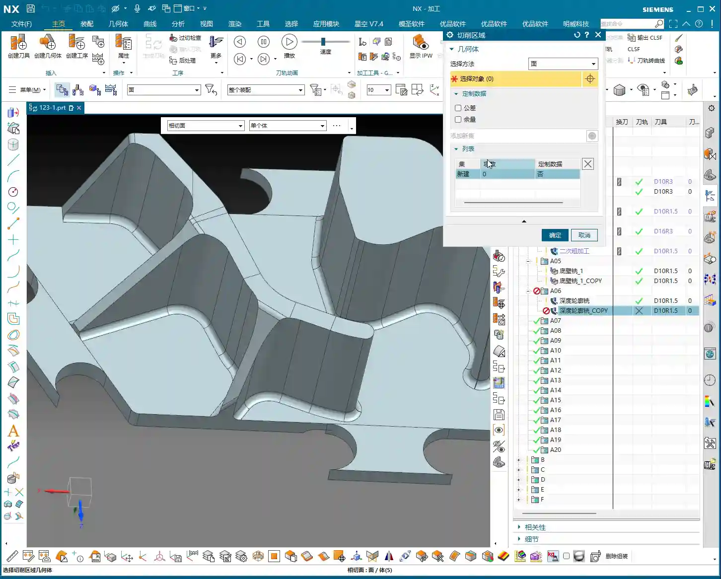
You mentioned that if certain sidewall areas are incorrectly or poorly selected, problems will arise. This is especially true for **tangent faces**, where automatic software selection can easily include faces that shouldn’t be machined, causing more trouble. In such cases, **manual intervention** is essential!
**Better Manual than Incorrect:** If the software’s automatic face selection isn’t reliable, then select them **one by one!** Don’t be afraid of the hassle; a few minutes spent now is insignificant compared to reworking or scrapping a part. Accurately select all sidewall faces that require a finish cut.
**Toolpath Trimming:** Remember, in some areas, if you let the tool run freely, it will generate redundant toolpaths, or even cause a **tool crash**. Therefore, you must **trim the toolpath**. Directly ‘cut’ away areas that don’t require machining, or where interference might occur, to ensure a clean and safe toolpath.
Coordinating Subsequent Bottom Surface and Sidewall Finishing Passes
We can duplicate the bottom surface **finishing pass** program, change the stock allowance to **0**, and let it completely finish the bottom surface. Then, perform another **finishing pass** on the sidewalls. For this sidewall **finishing pass**, continue to use the **D10R1.5 tool**, with a **1mm depth of cut** per pass. The goal is to allow the tool to finish all the way down to the bottom surface.
**Corner Radius Machining:** When encountering the small corner radii that were previously allowed for, you can adjust the corner radius parameter to **1.5mm** (or as per actual requirements). This step ensures smooth corner transitions, no burrs, and accurate dimensions.
**Safe Entry:** Tool entry must be safe; ideally, the tool should enter along the edge of the workpiece. This prevents interference and ensures machining stability.
Toolpath Optimization: Practical Wisdom on Retracts and Extensions
After finishing and generating the program, don’t rush to the machine. You still need to review the toolpath for any necessary optimizations; these are key factors affecting efficiency and final quality.
Rational Setting of Retract Height
You mentioned that the **retract height** is too high. This is a common issue! High **retracts** are purely a waste of time. Let’s change it to a **plane retract**, setting the **clearance distance** to **10mm** (or based on actual conditions, such as 5-10mm above the highest point of the workpiece). Remember, as long as it ensures no **tool crash**, keep the **retract height** as low as possible. Every second saved adds up; that’s how you gain efficiency!
The Necessity of Toolpath Extension
Another small detail is **toolpath extension**. Often, if you don’t extend the toolpath slightly, for example, by **0.3mm or 0.5mm**, it’s easy to leave a tiny unprocessed area at the end of the tool’s path. Don’t underestimate these few tenths of a millimeter; they can affect the entire surface finish and even lead to out-of-spec dimensions. So, when this happens, directly extend the toolpath slightly to ensure the tool fully cuts off the workpiece and completely cleans the area.
Balancing Efficiency and Tool Life
Finally, let’s talk about efficiency. For sidewall **finishing passes**, if you find a **1mm depth of cut** too slow and the stock allowance is relatively large, you can certainly take more passes, reduce the **depth of cut** per pass, and increase the feed rate. These adjustments are always based on actual conditions; there are no rigid, one-size-fits-all rules. Our goal is to maximize efficiency and minimize tool wear while maintaining quality. That’s how you make money, understand?
Summary: Pitfall Avoidance Guide
**Precise Stock Allowance Settings:** Don’t assume no stock allowance means it’s finished. Sometimes, leaving a minute allowance (e.g., **0.01mm**) can save significant trouble for subsequent **corner cleanup** and ensuring accuracy.
**No Laziness in Manual Face Selection:** When dealing with complex **tangent faces** and automatic software selection is unreliable, decisively switch to **manual face selection**, picking them one by one to ensure foolproof results.
**Toolpath Trimming is Essential:** Promptly trim redundant or risky toolpaths to prevent **tool crashes** and inefficient cutting.
**Rational Retract Height:** While ensuring safety, minimize **retract height** as much as possible. These small savings add up, improving overall machining efficiency.
**Toolpath Extension Prevents Uncut Areas:** For critical toolpath regions, remember to extend them appropriately to eliminate any unprocessed ‘dead spots’.
**Parameter Adjustment Based on Observation:** No matter how good the software simulation looks, ultimately you must observe the **cutting sparks** and the actual workpiece condition, flexibly adjusting parameters based on experience.
👤 About the Author: The author is a veteran CNC machining professional with 15 years of industry experience, specializing in UG NX programming. This article is an original work representing personal practical insights.
⚠️ Copyright Notice: Unauthorized reproduction or distribution without prior communication is strictly prohibited.
📝 Key Takeaways: ** NX Master Wang’s practical tutorial: Detailed explanation of rib roughing, focusing on conquering stock allowance control and tool selection challenges. Unveiling the ingenious use of auxiliary bodies, optimizing toolpaths to avoid pitfalls, and enhancing machining efficiency and precision. Learn the real skills! **
Listen up, folks, it’s Master Wang here. Last time, we discussed the blank dimensions and general strategy for the outer frame. This time, we’re getting down to serious business—we’re going to start programming this part, especially the roughing of these ribs and stock allowance control. This is where the real skill shines in practical machining! Don’t think it’s just about clicking a few buttons in NX; there are no do-overs on the actual machine.
Step One: Part Analysis and Initial Tool Selection
When you get a part, the first thing isn’t to rush into NX. Instead, use your keen eye and calipers to check all the dimensions. Especially those arcs and radii; their sizes directly determine the diameter of your first tool and its Depth of Cut.
Getting Down to Basics: Radii are Key
For this part’s radii, we measured the outside to be R2, and some internal ones are R5. An R5 means we’ll need at least an R2.5 tool to clean it out properly. But for roughing, considering efficiency and tool strength, we can start with a larger one.
As we discussed, for roughing, a Ø12R2 or Ø16R2 tool would work. After checking inventory, I found a Ø16R1.5 tool to be more suitable. It meets most roughing demands and offers good tool commonality. There’s no perfect tool, only the one best suited for the current operation.
For side walls and flat surfaces, we’ll pick a Ø6 ball end mill later for Contour Milling; nothing much to say there.
Parting Off Operation: To Be Discussed Later
Oh, and for the final parting off operation, use a Ø10 flat end mill. We’ll cover that separately later. Today, let’s focus on Roughing; don’t try to take on too much at once.
NX Environment Setup: Blank and Part Definition
In NX, coordinate systems, blanks, and parts are always discussed, but the more fundamental something is, the less you can afford to be careless. Get your Work Coordinate System wrong, and everything after it is useless. The blank dimensions are 100x100x200mm; we covered this last time. Just set it up, no need for more talk.
Clever Use of Main Part and Auxiliary Bodies
When defining the “part,” we need to select all solid faces as the machining object. However, there are some areas we might not want to machine in the current operation, or we want to save them for a later setup. This is where we bring in the good old “auxiliary body”.
For instance, the top plane of this part: to prevent the toolpath from wandering or having excessive retracts during roughing, we can temporarily exclude it from machining.
I usually create an extruded body, extending it beyond the blank dimensions, to serve as our “auxiliary body”. In programming, set it as a “check geometry” or “trim boundary”. This way, the tool will either avoid it or only cut within its defined limits. This is a practical skill you won’t learn from textbooks; it’ll save you a lot of headaches and reduce air cutting.
Don’t forget, the sides of the part should be handled similarly, as we plan to flip them over for machining later. So, we’ll leave them untouched on this setup.
Roughing in Practice: Ribs and Outer Frame
Now, let’s get to the actual material removal. Roughing these ribs requires a “steady” approach: first, aggressive cutting, then fine-tuning.
First Pass Roughing: Ø16R1.5 and Stock Allowance Control
We’ll use a Ø16R1.5 tool with a “Follow Periphery” toolpath. This is the most common roughing strategy, offering high efficiency.
Here’s the critical part! For the outer frame, we’re leaving no stock allowance during roughing; we’ll machine it directly to size. Why? Because the outer frame is typically quite regular, allowing for direct finishing, which saves an operation and money! However, for internal ribs and other part features, you must leave a 0.3-0.5mm stock allowance. This provides sufficient material for subsequent semi-finishing and finishing passes, ensuring final accuracy and surface quality. Don’t underestimate a few tenths of a millimeter; it can save your hide!
In NX, remember to set the stock allowance for the outer frame to 0, and for internal features, set it to 0.3mm.
When simulating the toolpath, observe carefully. You might find some areas where the toolpath isn’t ideal, perhaps only two passes, or unnecessary retracts. Don’t panic! This isn’t the software’s fault; it’s an issue with our strategy. For these less-than-ideal areas, if they’re not critical dimensions or can be resolved in subsequent operations, leave them for now. Or, as I mentioned, use an auxiliary body to isolate them and deal with them later.
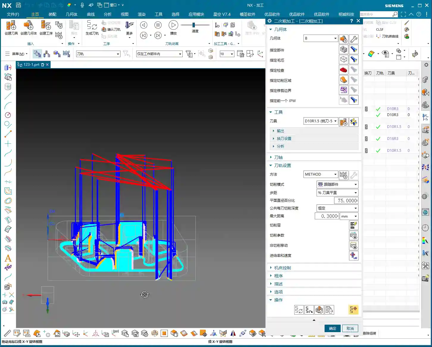
Secondary Roughing: Precision Corner Cleanup for Ribs
After the initial Roughing, those tight corners and areas the previous tool couldn’t reach will need to be cleaned up with secondary roughing.
Select a Ø10R2 tool. If it’s not in your tool library, create one. Name it clearly, something like “D10R2”, for easy management.
Continue to leave about 0.35mm stock allowance, providing room for the Finishing pass.
Controlling the Depth of Cut per pass (or layered cutting) is crucial. Don’t try to machine it all in one go; the tool won’t handle it, and you might even chip it. Based on the material and tool, set the axial Depth of Cut (AP) to 0.6mm or 0.7mm. This ensures both efficiency and tool protection.
When checking the toolpath, pay special attention to the roots of the ribs, ensuring the tool effectively removes the remaining material from the previous roughing pass. This is fundamental for a smooth finishing pass.
Summary: Pitfall Avoidance Guide
Corner Radius Dictates Tool Selection: The smallest radius on the part is the deciding factor for selecting your tool radius. For Roughing, you can use a slightly larger radius, but not excessively so.
Clear Stock Allowance Strategy: For non-critical mating surfaces like the outer frame, you can directly machine to size (0 stock allowance). But for internal mating surfaces, ribs, etc., you must leave sufficient stock allowance (e.g., 0.3mm); this is your “fallback” for Finishing passes.
Auxiliary Bodies are Great Helpers: Make good use of auxiliary bodies as “check geometry” or “trim boundaries” to effectively control toolpath boundaries, avoid air cutting, optimize machining paths, and reduce unnecessary retracts.
Layered Cutting for Tool Protection: During Roughing, don’t be greedy with your Depth of Cut. Set the DOC per pass reasonably to both improve efficiency and extend tool life, reducing costs.
Don’t Blindly Trust Simulation: No matter how realistic software simulation is, it’s still just a simulation. Ultimately, you need to observe the cutting sparks on the machine and listen to the cutting sounds—those are the real feedback. If you find issues in simulation, think about them. If you encounter issues on the machine, you must stop and analyze.
Multi-dimensional Consideration: Programming isn’t a one-off task; you must consider subsequent operations, and even the entire machining workflow. For example, if you don’t machine this face now, can it still be completed after flipping the part? All of this needs to be planned in advance.
That’s all for today. These are insights I’ve gathered from fifteen years of hard work on the shop floor, and I hope they help you. Don’t just listen; get hands-on, practice, and think critically to truly master these skills! Next time, we’ll talk about something else.
👤 About the Author: The author is a veteran CNC machining professional with 15 years of industry experience, specializing in UG NX programming. This article is an original work representing personal practical insights.
⚠️ Copyright Notice: Unauthorized reproduction or distribution without prior communication is strictly prohibited.
📝 Key Takeaways: Master Wang guides you through practical Siemens NX Guiding Curve Machining, focusing on how to select guiding curves in ‘Deformed Mode.’ Emphasizes that guiding curve arrow directions must be consistent to avoid chaotic toolpaths and scrap. Reveals the secret to controlling toolpath direction via guiding curves, solving complex surface machining challenges, enhancing machining accuracy and efficiency, and preventing thermal deformation.
Hello everyone, I’m Master Wang. Today, we’re going to continue digging deep into the intricacies of Siemens NX programming to discuss ‘Guiding Curve Machining,’ a feature that often baffles newcomers but is indispensable for experienced machinists. This powerful tool has only been available since Siemens NX 12.0; older versions didn’t have this capability!
Master Wang’s Lecture: Siemens NX Guiding Curve Machining – An Expert’s Guide to Avoiding Pitfalls
Listen up. This ‘Guiding Curve Machining’ is quite similar to ‘Surface Milling,’ which we’ve covered before. Both are used for finishing passes. Especially for complex surfaces and small radii, both can generate excellent toolpaths. Sometimes, the programs they produce can even be identical.
Guiding Curve Machining vs. Surface Milling: Different Approaches, Complementary Strengths
Don’t underestimate these two; although they seem similar, each has its own quirks. For some jobs, Guiding Curve Machining performs better, generating a smoother toolpath; for others, Surface Milling is the way to go. So, don’t be rigid – if one doesn’t work, switch to the other. That’s practical experience talking! I’m telling you, textbooks won’t teach you these adaptable methods. For example, when machining certain complex freeform surfaces, Guiding Curve Machining often conforms better to the surface, reducing retracts and improving efficiency. Whereas Contour Milling (a type of Surface Milling) might perform better on steep areas.
Advanced Siemens NX Feature: The Evolution of the Guiding Curve Command
The true power of this ‘Guiding Curve Machining’ command began to emerge with Siemens NX 12.0; it wasn’t available in earlier versions. Its biggest change is the interface. Now, if you open this command in Siemens NX 1980 or higher, you’ll find its parameter interface is different from before; many options have moved to a sidebar, making it look cleaner. But let me emphasize: What if the interface changed? The core parameters and underlying algorithms remain the same! So, when you’re learning, just grasp the core logic; don’t get bogged down by minor interface changes. Personally, I prefer the higher version interface; it’s more efficient to operate.
Practical Essentials: Machining Workflow and Key Settings
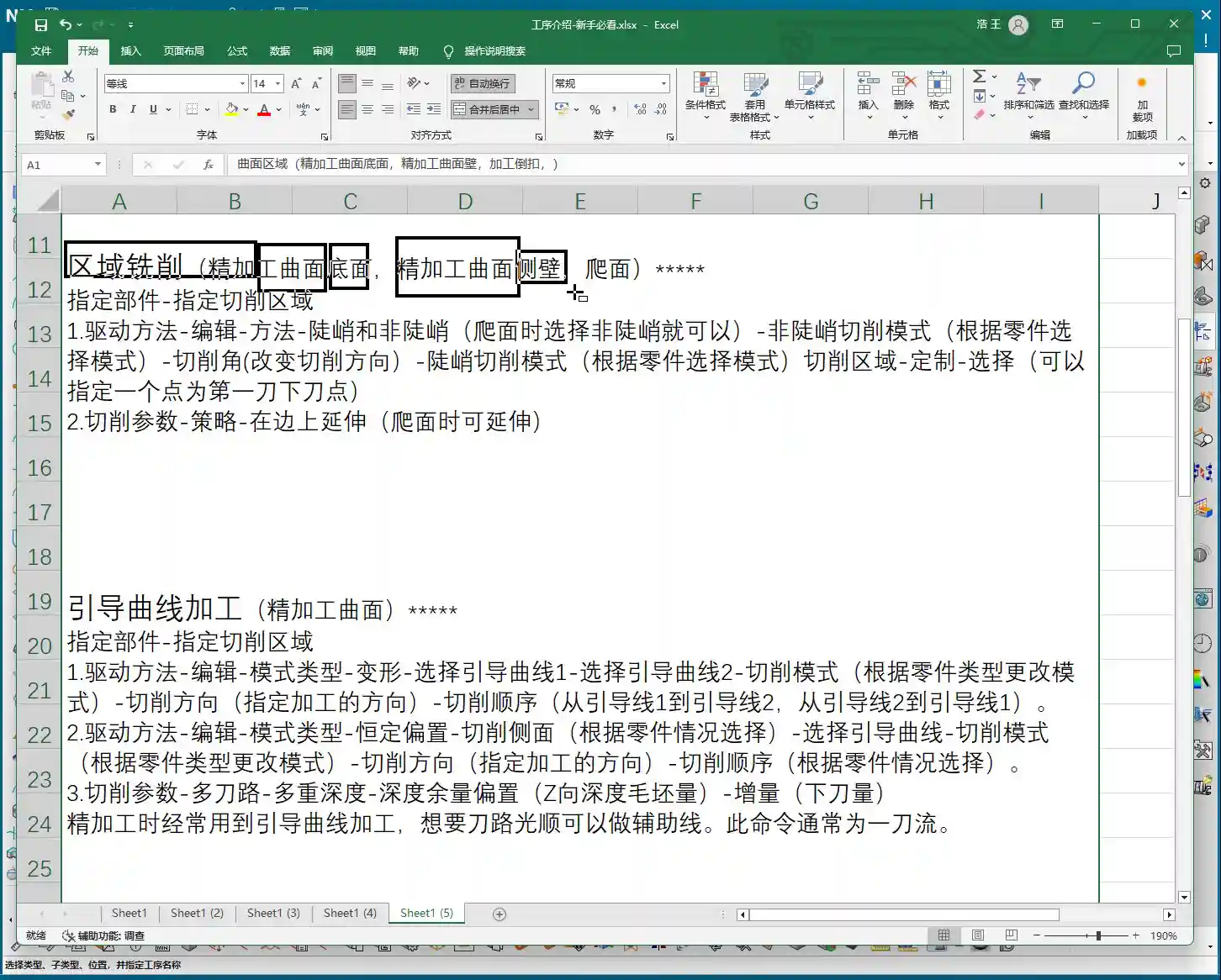
Step One: Coordinate System Setup and Workpiece Fixturing
Standard procedure: before you start working, the Work Coordinate System (WCS) must be correctly oriented. You can place it anywhere, as long as you’ve clearly defined the directions of the X, Y, and Z axes. Remember, for 3-axis machining, the tool axis direction is generally fixed, so establish your WCS first to avoid issues later. It’s the same principle as drafting: a shaky foundation leads to collapse!
Tool Selection and Machining Area: The Foundation of Finishing Passes
Next, select your tool. For finishing passes, you typically use a ball end mill. The tool diameter will depend on the fillet radius of your part and the required accuracy. Then, select the area you intend to machine – it could be a single face or multiple faces. Don’t just rely on standard tools from the library; sometimes, for optimal machining efficiency and surface quality, I’ll even grind a custom tool myself. That’s not something you learn from textbooks; it comes purely from experience.
One more thing to note: options like tool axis control (e.g., ‘Axis and Necessary’) are generally not used in 3-axis machining; those are for 5-axis operations. Leave them alone for now, or you’ll just get yourself confused.
Mode Type: Understanding the ‘Deformed’ Selection and Its Function
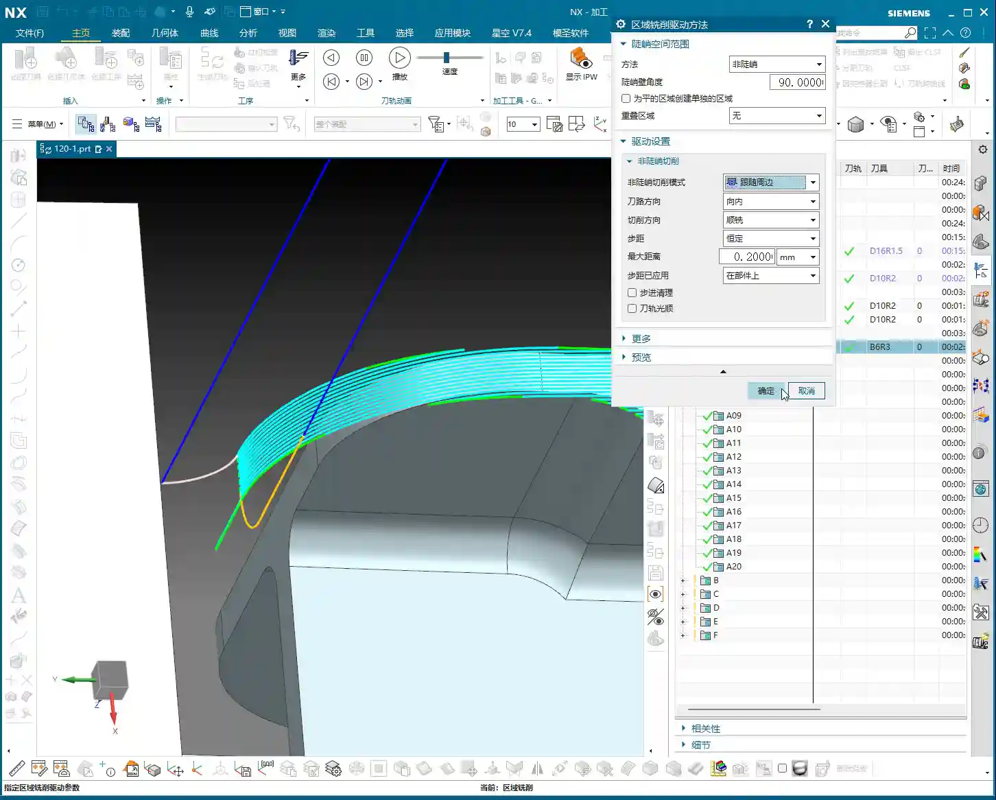
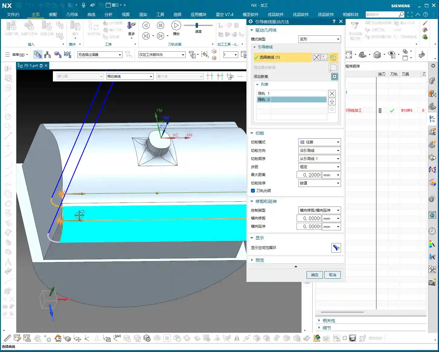
Here’s the critical part! In the parameter settings for ‘Guiding Curve Machining,’ there’s an option called ‘Mode Type.’ Click the ‘wrench’ icon next to it (which is the ‘Edit’ button), and you’ll see several modes. The most commonly used are ‘Deformed’ and ‘Constant Offset.’ Today, we’ll focus on ‘Deformed’ as an example.
The ‘Deformed’ mode has its own peculiarities; it requires you to select two guiding curves. These two curves act like a ‘track’ for the tool; the tool will operate between them, forming the machining path. This is somewhat similar to selecting two boundary lines when we learned ‘Planar Profile Milling,’ both serving to define the tool’s range of motion.
Master Wang’s Secret Techniques: The Mysteries of Guiding Curve Selection and Direction Control
Selecting Guiding Curves: Where from, where to?
Selecting guiding curves is straightforward, just like selecting wireframe geometry. First, click the initial curve, then click ‘Add New Geometry’ or simply press the middle mouse button, and then select the second curve. These two curves can be closed or open, as long as they define your desired machining area.
However, there’s a crucial detail here, and it’s where many newcomers stumble.
🚨[Pitfall Alert] The Iron Rule of Direction: Guiding Curve Arrows MUST Match!🚨
After you select two guiding curves, you’ll see a small arrow on each curve. This arrow indicates the curve’s direction. Listen carefully: the arrow directions of these two guiding curves must, and can only, be consistent! They either both point in one direction or both point in the other. Absolutely never one left, one right!
I’ve seen too many newcomers fail to pay attention to this when selecting curves, resulting in toolpaths that are either chaotic or immediately trigger errors. Sometimes, even the software simulation looks fine, but the moment you put it on the machine, the cutting sparks look wrong, the part precision is way off, or it even experiences tool deflection and becomes scrap! This is no joke; one wrong direction, and your whole day’s work is wasted, with costs pouring out! If you find the arrow directions inconsistent, simply right-click the curve and select ‘Reverse’; it’s quite simple.
Impact of Different Guiding Curve Selections on Toolpath Direction
The most powerful aspect of this ‘Deformed’ mode is that your chosen guiding curves directly determine the toolpath direction. This is crucial in practice for controlling machining patterns, preventing thermal deformation, and even for fine error compensation!
Case One: Horizontal Guiding Curves, Vertical Machining.
If your selected two guiding curves are two parallel horizontal lines on the upper part of the workpiece (e.g., the upper and lower edges of a curved surface), then the generated toolpath will machine from top to bottom, or bottom to top, along a direction perpendicular to the guiding curves. This is like using a roller to paint a wall from top to bottom.
Case Two: Vertical Guiding Curves, Horizontal Machining.
Conversely, if your selected two guiding curves are two parallel vertical lines on the sides of the workpiece (e.g., the left and right edges of a elongated feature), then the generated toolpath will machine from left to right, or right to left, along a direction parallel to the guiding curves. This is like using a roller to paint a wall from left to right.
See that? The choice of guiding curves dictates your tool’s cutting direction! This is especially crucial during finishing passes. For instance, some materials, like titanium alloys or high-temperature nickel-based alloys, are highly sensitive to cutting direction and cutting forces. If the direction is incorrect, it can easily lead to work hardening or thermal deformation. By precisely selecting the guiding curves, you gain control over the tool’s path, bypassing the material’s ‘temperament’ and ensuring part quality and accuracy. What’s more, even when facing minute machine precision errors of around ±0.005mm (approx. 0.0002 inch), I resolve them by adjusting guiding curves and implementing process compensation – now that’s true expertise!
So, practice frequently, generate toolpaths using different guiding curve combinations, and observe the variations. Gradually, you’ll grasp the subtleties. This is far more useful than simply memorizing theoretical formulas!
Summary: Pitfall Avoidance Guide
Mode Type Selection: For machining complex surfaces, especially when toolpath direction control is critical, prioritize ‘Deformed’ mode or ‘Constant Offset’ mode.
Two Guiding Curves Required: ‘Deformed’ mode necessitates selecting two guiding curves, which define the tool’s operating range.
The Iron Rule of Arrow Direction: Regardless, the arrow directions of both guiding curves must be consistent! This is crucial for correct toolpaths and avoiding scrapped parts. Otherwise, the toolpath will be chaotic, cutting will be unstable, and accuracy will be completely compromised.
Toolpath Direction Control: By selecting guiding curves in different orientations, you can precisely control the tool’s cutting direction. This is vital when dealing with material characteristics, surface finish, and preventing deformation.
Software Version Differences: While interfaces may differ between older and newer versions, core parameters and functionalities remain constant. Learn to apply knowledge broadly and grasp the underlying logic.
Alright, that’s all for today. Practice and experiment a lot; you’ve got to get hands-on with these machines; you won’t learn by just watching. Next time, we’ll discuss other practical tips. See you then!
[EXCERPT]: Master Wang guides you through practical Siemens NX Guiding Curve Machining, focusing on how to select guiding curves in ‘Deformed Mode.’ Emphasizes that guiding curve arrow directions must be consistent to avoid chaotic toolpaths and scrap. Reveals the secret to controlling toolpath direction via guiding curves, solving complex surface machining challenges, enhancing machining accuracy and efficiency, and preventing thermal deformation.
👤 About the Author: The author is a veteran CNC machining professional with 15 years of industry experience, specializing in UG NX programming. This article is an original work representing personal practical insights.
⚠️ Copyright Notice: Unauthorized reproduction or distribution without prior communication is strictly prohibited.
📝 Key Takeaways: ** Master Wang provides a hands-on guide to Siemens NX cavity **roughing** strategies. Drawing from 15 years of practical experience, Master Wang meticulously explains the intricacies and pitfalls of each parameter, from cutting order and toolpath direction to stock settings and non-cutting moves. This helps you optimize toolpaths, enhance machining efficiency and precision, moving beyond textbook theory to address real-world production challenges. **
Hello everyone, I’m Master Wang. Today, we’ll continue discussing Siemens NX cavity milling operations. Last time, we covered some fundamental program creation. Today, we’re diving deep into the internals of cutting parameters to share practical tips you won’t find in textbooks. Listen closely, because a slight oversight in these areas can lead to **tool deflection** or significantly reduced efficiency.
Key Parameters for Cavity Roughing Strategy in Siemens NX
Cutting Order: The Wisdom of Depth First
As we’ve discussed before, Siemens NX provides options for Depth First and Level First. I always say that for cavity **roughing**, in most cases, we’ll opt for Depth First. Why?
Improved Chip Evacuation: Depth First allows the tool to cut to a specified depth within one area first. This creates more space for chips to evacuate, preventing clogging and reducing re-cutting, naturally extending tool life.
High Cutting Stability: With each **stepdown**, the cutting load remains relatively stable. Unlike Level First, which sweeps through the entire area layer by layer, switching back and forth, Depth First helps avoid vibrations that can affect machining accuracy and surface quality.
Of course, this isn’t an absolute rule; special situations require special handling. However, defaulting to Depth First is usually the right choice.
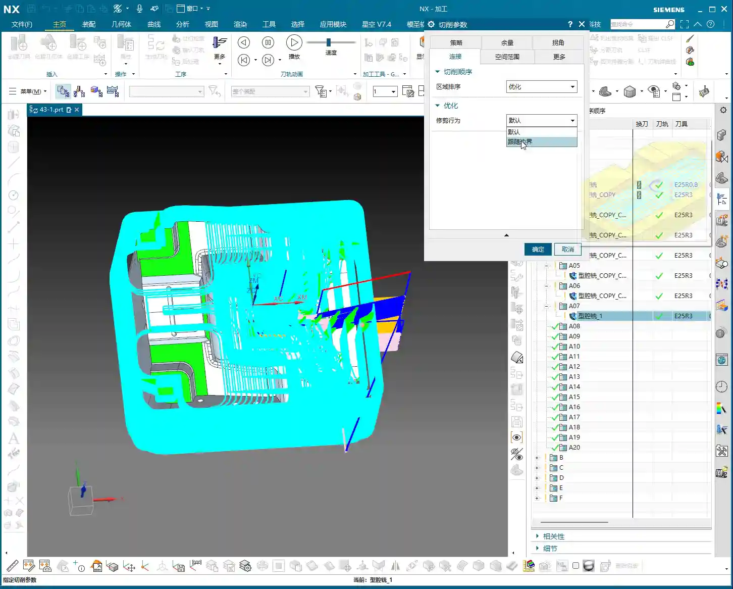
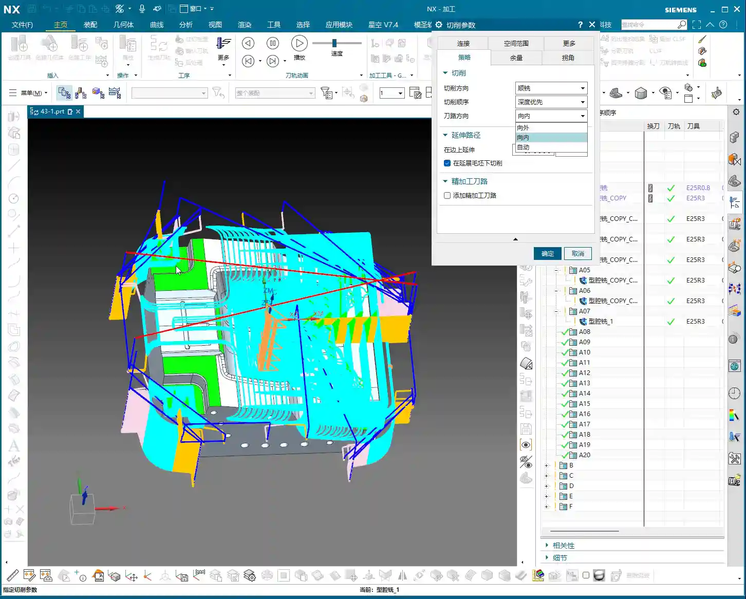
Toolpath Direction: The Secret of Smart “Automatic”
Toolpath direction used to only offer a few options: Inward and Outward. Inward means milling from the outside in, and Outward means milling from the inside out. For enclosed cavities, Inward might be better; for open cavities, Outward might be smoother. But did you know that Siemens NX now has a particularly useful option called Automatic!
Automatic Detection, Doubled Efficiency: This “Automatic” function isn’t just a random choice. The software intelligently determines whether the current area should be cut “Inward” or “Outward” based on your part’s geometric features, such as whether it’s an enclosed cavity or has open boundaries. This significantly reduces idle cuts. For instance, in open areas, it will directly enter the material from the outside, avoiding plunging inside solid material before moving outward.
Reduced Manual Intervention: Especially for complex parts with a mix of enclosed and open areas, manually distinguishing and setting these parameters would be time-consuming and prone to errors. Entrusting it to “Automatic” saves effort, reduces hassle, and results in more optimized toolpaths.
Therefore, under normal circumstances, simply use “Automatic” here. Don’t underestimate this small option; it can save you a lot of valuable machine time.
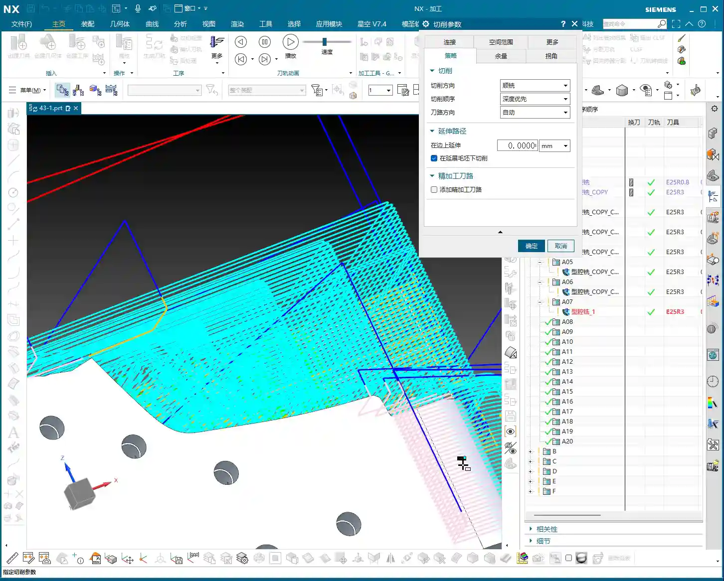
Cut Along Blank Underneath: The Choice for Multi-Sided Machining
This parameter, called Cut along Blank Underneath, determines whether the tool should continue cutting into the blank material below the currently defined cutting layers. Let me give you an example, and you’ll understand immediately.
Imagine a part where you first machine Face A, then flip it over to machine Face B. Face A has already been **roughed** to a certain depth, but this depth might have cut past the part’s centerline, or even slightly into a portion of the blank material that will be machined for Face B. Now you’ve flipped it over and begun machining Face B.
If checked (default is checked): Even if the defined machining range for Face B is sufficient up to a certain depth, if there’s still blank material below that depth, the tool will continue to cut downwards until all blank material is removed. This could lead to re-cutting areas already machined on Face A, or cutting into unintended areas. For multi-sided machining with part flips, this might result in over-cutting or idle moves.
If unchecked: The tool will strictly adhere to the part boundaries defined for the current operation. It will only cut the blank material that is above or on the part’s surface for the current operation. Even if there’s a significant amount of material below the part surface, it won’t be touched. This is extremely useful in multi-sided machining or when pre-machining has occurred, ensuring the tool only removes the necessary stock for the current face, avoiding unnecessary deeper cuts, saving time, and enhancing safety.
So, when performing multi-sided machining or operations with pre-machined features, you must carefully consider this option. The default checked state may not be suitable for all situations; sometimes, unchecking it can lead to smarter and safer toolpaths.
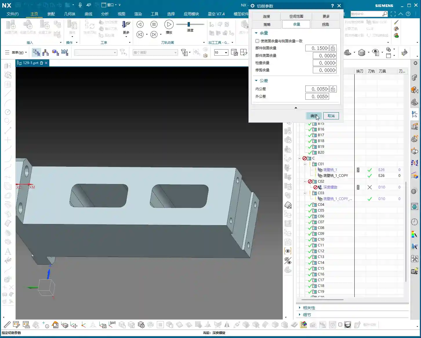
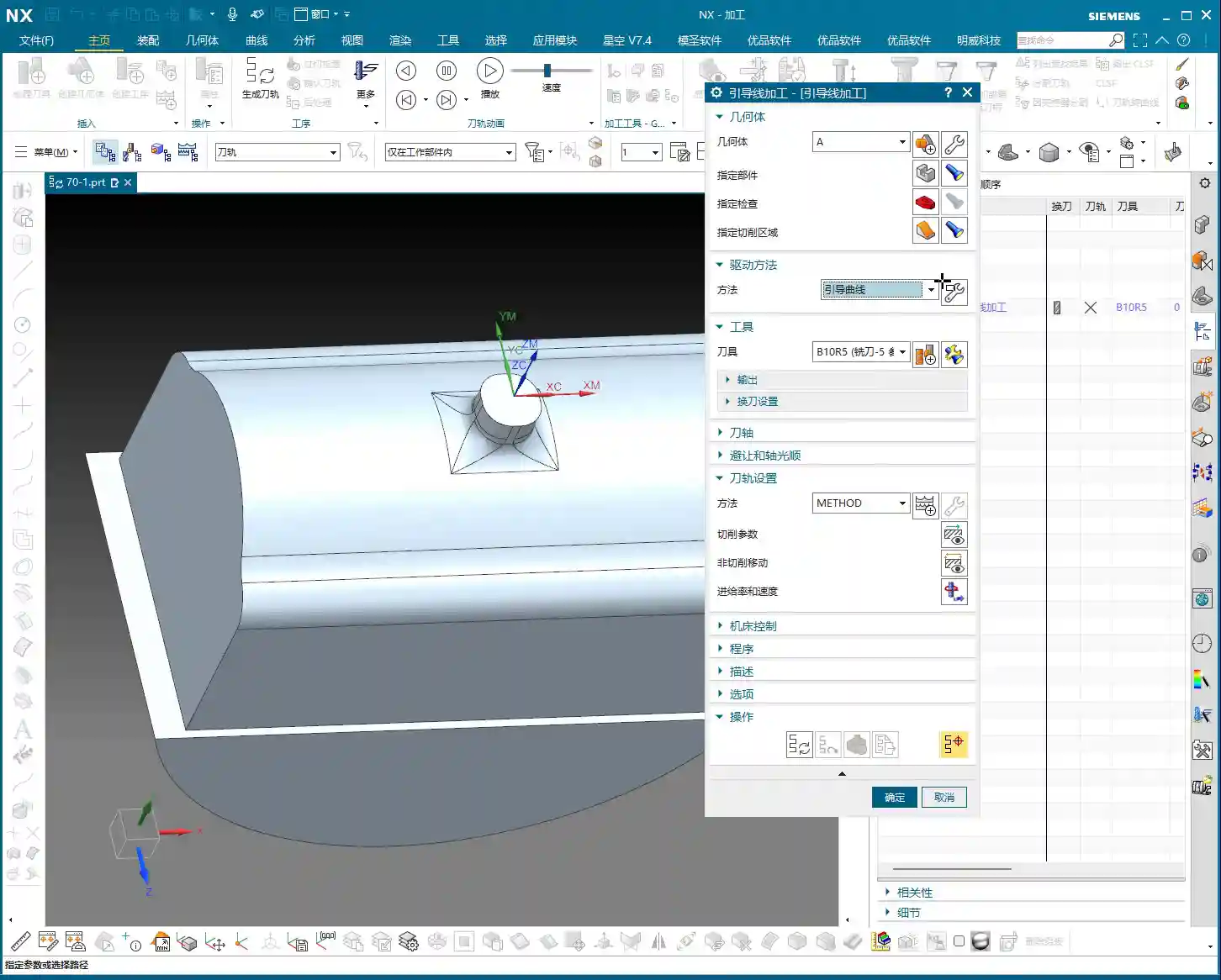
Stock Settings: Crucial for Roughing and Finishing
Stock is material left for **finishing passes**. During **roughing**, Side Stock and Bottom Stock are usually set to a positive value. For example, during **roughing**, we typically leave about 0.3 mm (approx. 0.012 inch). This value isn’t arbitrary; it must be determined by considering your machine’s precision, tool rigidity, material hardness, and the allowance for the **finishing pass**.
Roughing Stock: If too little stock is left, the **finishing pass** tool will experience excessive load, leading to wear or even chipping. If too much stock is left, the **finishing pass** will involve too many cuts, wasting time. Therefore, finding this balance point, relies on experience and practical considerations.
Finishing Stock: The stock for **finishing passes** is much smaller, typically 0.15 mm (approx. 0.006 inch) or even less, to ensure final dimensions and surface finish.
Individual Stock Control: Flexible or Unified?
Siemens NX features a small checkbox here. If you enable it, Side Stock and Bottom Stock will be linked. This means if you change one, the other will update automatically. For example, if you want both to be 0.2 mm (approx. 0.008 inch), just check the box and modify one. If you want 0.2 mm for the side and 0.3 mm for the bottom, then uncheck the box and set them separately.
My recommendation is, unless your stock requirements for side walls and bottom surfaces are absolutely identical, it’s best to set them separately. This provides greater flexibility and better adapts to the machining needs of different parts. For instance, the **finishing pass** at the bottom of some deep cavities might be challenging, potentially requiring more stock.
Blank Stock: The Art of Precise Positioning
The Blank Stock parameter essentially offsets the blank model we initially created outwards by a certain distance. For example, if you set it to 10 mm (approx. 0.39 inch), your existing blank model is expanded by 10 mm.
As Master Wang, I generally don’t use this function much. Why? Because we typically directly create a precise solid blank model or use offset geometry to define the blank. This is more intuitive, accurate, and better reflects the actual blank dimensions. Directly applying an offset value here can sometimes lead to confusion with the actual blank size, and accuracy can be compromised, especially with complex blank shapes. Unless absolutely necessary, don’t use this feature carelessly.
Check Stock and Trim Stock: Ensuring Safety and Efficiency
Check Stock: This parameter is used to prevent collisions between the tool and **fixturing** components like clamps or pressure plates. You can model your **fixturing** in Siemens NX and then set a check stock for it, for example, 0.5 mm (approx. 0.02 inch). This way, the tool will automatically avoid the fixture, leaving a 0.5 mm gap, ensuring machining safety. This is a critical safety parameter, and you must be mindful of it, especially in complex **fixturing** setups or close-tolerance machining.
Trim Stock: When you use trim boundaries to limit the toolpath range, this parameter defines the stock left relative to the trim boundary. It can be set to be Inward or Outward. For instance, if you’ve drawn a boundary and want the toolpath to retract slightly inward from that boundary, you can set a positive value. This is very useful for local **corner cleanup** or avoiding specific areas.
Inner/Outer Tolerance and Corner Handling: Details Determine Quality
Inner/Outer Tolerance: These two control toolpath accuracy. During **roughing**, a larger tolerance can be applied, such as 0.1 to 0.3 mm (approx. 0.004 to 0.012 inch), as the primary goal of **roughing** is rapid material removal. However, for **finishing passes**, the tolerance must be very small, typically 0.01 mm (approx. 0.0004 inch) or even less, to ensure the final part dimensions and surface finish meet requirements.
Corners: This parameter controls whether a transition radius is applied to the toolpath when entering or exiting corners. During **roughing**, we typically apply a small transition radius, such as 0.2 mm or 0.5 mm (approx. 0.008 or 0.02 inch). This offers several benefits:
Tool Protection: Prevents the tool from sudden changes in direction at sharp corners, reducing impact, tool wear, and chipping.
Smooth Cutting: Results in smoother toolpaths and more stable machine operation, reducing vibrations and helping maintain machining accuracy.
The specific size depends on the tool diameter, material hardness, and how much sharp corner material you aim to remove during the **roughing** stage.
“Cutting Flatness” in Non-Cutting Moves: Guardian of Tool Life and Machining Quality
This parameter, found under Non-Cutting Moves, is called Cutting Flatness. Don’t underestimate it; it significantly impacts tool life and machining quality, especially when using indexable insert tools or certain end mills without a center cutting edge.
Its purpose is to prevent the non-cutting parts of the tool (such as the tool center or the non-cutting body of an indexable insert) from scraping the bottom of the workpiece when encountering flat bottom regions, which could degrade surface quality or cause tool wear. It is typically defined as a percentage of the tool diameter.
Practical Significance: If you set an excessively large value, for example, 10 mm (approx. 0.39 inch) (relative to a tool with a small diameter), and the tool’s effective cutting length or insert height is much smaller than this value, then in flat areas, the tool body will **”gouge”** or directly impact the workpiece, leading to tool damage or scrapped parts.
Recommended Setting: We typically assign a percentage, such as 45% to 65%. This means that when the **depth of cut** or the dimension of a flat region encountered is less than this percentage, the tool will adopt strategies like lifting, arc transitions, etc., to prevent non-cutting portions from contacting the workpiece. This both protects the tool and ensures the flatness and finish of the bottom surface.
This parameter is especially crucial for expensive indexable insert tools; you must understand it thoroughly and never change it haphazardly!
Summary: Pitfall Avoidance Guide
In our line of work, simply relying on textbook theory isn’t enough; you must combine it with practical experience. The parameters discussed above are insights I’ve gathered from 15 years of hands-on experience in the field – every word is valuable. Finally, here are a few reminders, born from hard-learned lessons:
Don’t Arbitrarily Choose Cutting Order: Unless you have specific requirements, “Depth First” is the primary choice for cavity roughing. Blindly using “Level First” can easily lead to poor chip evacuation, rapid tool wear, and even chip packing or tool breakage.
Trust “Automatic” for Toolpath Direction: For complex cavities, manually selecting “Inward/Outward” can result in numerous idle cuts and low efficiency. Modern software is intelligent; make frequent use of “Automatic”. It will help you find the most logical path, saving you significant time in judgment and adjustment.
Thoroughly Understand “Cut Along Blank Underneath”: Especially in multi-sided machining or when pre-machining has occurred, misunderstanding this option can lead to re-cutting already machined surfaces, or plunging the tool in unintended areas. At best, this wastes time; at worst, it causes tool crashes and scrapped parts. Before each multi-sided machining operation, always check or uncheck this option based on the actual situation and simulate carefully.
Stock Settings Require Balance: If **roughing** stock is too small, the **finishing pass** tool won’t have a consistent cut, leading to **tool deflection** or chipping. If too large, it increases the **finishing pass** burden and wastes time. You must find the optimal sweet spot based on material, tool, and machine conditions.
Blank Stock, Use with Caution: Unless the blank shape is extremely simple, do not solely rely on this parameter to define complex blanks. It’s best to use solid blank models or offset curves to minimize errors.
“Cutting Flatness” is Key: For indexable insert tools or flat-bottom end mills, improper settings for this parameter can cause the tool center or non-cutting portions to scrape the bottom of the workpiece, affecting surface finish or even damaging the tool. Default values are often based on experience, but you should still understand the underlying principles based on the tool and workpiece characteristics.
Remember, these parameters are static; the machinist is dynamic. Observe cutting sparks, listen to machine sounds, and think critically—experience will naturally follow. All right, that concludes today’s lesson. We’ll discuss something else next time.
👤 About the Author: The author is a veteran CNC machining professional with 15 years of industry experience, specializing in UG NX programming. This article is an original work representing personal practical insights.
⚠️ Copyright Notice: Unauthorized reproduction or distribution without prior communication is strictly prohibited.
Alright, listen up, everyone! Today, Master Wang will walk you t…
[VIDEO_HERE]
Alright, listen up, everyone! Today, Master Wang will walk you through a common machining case for reinforcing ribs on a component. This might look straightforward, but there’s a lot more to it, especially when it comes to toolpath optimization and preventing heavy tool engagement – that’s the real-world know-how you won’t find in textbooks. We’ll start from scratch and machine both the back and front sides, step by step.
I. Workpiece and Coordinate System Setup: Poor Foundation, Everything Crumbles!
First, once you get the part drawing, you need to understand it thoroughly. These reinforcing ribs aren’t complex in shape, but you need to pay attention to their structural characteristics during machining. Here, it’s fine to machine a little more, but the critical thing is not to damage other areas.
1.1 Workpiece Placement and Fixturing
The first and most crucial step is workpiece placement and fixturing. No matter how advanced your machine tool is, if the fixturing isn’t solid, everything else is useless. Typically, for these reinforcing ribs, we’ll place them on a robust fixture to ensure stability during the machining process. I usually just put it directly on the fixture, simple and straightforward.
1.2 Creating Machining Geometry and WCS
In Siemens NX, we enter the manufacturing module and first create the machining geometry and the WCS (Work Coordinate System).
Select the “A” coordinate system as the main coordinate. No need to elaborate, it’s the same every time.
You should be familiar with the tools preset in the tool library, for example, a Ø16 flat end mill, a Ø12 flat end mill, or corner radius end mills. We’ll select others later based on actual requirements.
II. Roughing the Back Side of Reinforcing Ribs: Tool Deflection is No Laughing Matter!
Let’s start with the back side. For these reinforcing ribs, the back side is typically the first operation; we need to rough out its general shape first.
2.1 Tool Selection and Machining Area
Right-click to insert an operation, select “Cavity Mill”. This surface is clearly best suited for Cavity Milling.
Part Geometry: Directly select the main body of our reinforcing rib.
Tool Selection: First, analyze its corner radius (R-angle). Upon measurement, we find it’s approximately R3. Alright, then directly choose an R3 ball end mill or a corner radius end mill. This way, most of the material can be removed in one go without overcutting.
Depth of Cut (DOC): It’s approximately 1.4mm. We’ll take a 0.2mm stepdown per pass, taking several passes.
2.2 Toolpath Optimization: No Plunge Cuts!
Generating the toolpath, woah! The tool plunges directly in – that’s unacceptable! Plunge cutting is a major taboo in machining; it can lead to tool breakage, scrap the workpiece, or even damage the machine. Listen up, you must never allow the tool to plunge directly!
Entry Method Adjustment: In the cutting parameters, change the entry method from the default ‘Direct Plunge’ to ‘Helix or Ramp entry along boundary‘. This way, the tool spirals down like a drill, ensuring even cutting forces, which is better for both the tool and the workpiece.
Master Wang’s Tip: Don’t just rely on software simulation; observe the cutting sparks and listen to the cutting sound. When spiraling down, the sparks will be uniform, and the sound will be stable – that’s the sign of a good toolpath!
Stock Allowance Setting: For roughing, leaving some stock allowance is essential. Leave a 0.15mm allowance; we’ll finish it later during the finishing pass.
2.3 Avoiding Side Load/Chatter: Safety Distance is Key!
When the program runs, you might notice the tool still ‘stumbling’ in some areas, especially when cutting slopes. This indicates insufficient safety distance.
Minimum Safe Distance: This parameter might not have been mentioned much before, but it’s extremely practical. Set it to 0.2mm or even 0.3mm. You’ll notice that the tool will approach the machining area from outside with a safe distance before smoothly entering the cut. This avoids the risk of sudden heavy engagement or tool deflection on slopes.
Cutting Angle Adjustment: For this slope angle, we can adjust it slightly, for instance, from the default 8 degrees to 5 degrees. This makes the tool’s plunge into the material gentler, leading to more stable machining.
III. Roughing the Front Side of Reinforcing Ribs: The Clever Use of Auxiliary Geometry
With the back side done, now let’s tackle the front side. The situation on the front is similar, but we can try some different strategies.
3.1 Copying Operations and WCS Switching
To save time, simply copy the roughing program for the back side. Then modify the WCS, rotate it 180 degrees, and switch to our B coordinate system (offset set to 100, which is for distinction).
3.2 Stock Definition and Auxiliary Geometry Selection: Trade-offs with the Workpiece Feature
In the past, we often used the Workpiece feature (for stock definition). However, for complex parts with reinforcing ribs, using Workpiece sometimes requires creating many auxiliary bodies just to define the stock, which can be quite cumbersome. Therefore, when dealing with these types of parts, I personally prefer to directly select the geometry to define the machining area, which is more efficient.
Stock Definition: Let’s redefine the stock, setting it to 0 (relative to the part). Then select the part body and its external contours. Also, initially set a stock allowance of 0.01mm.
Tool Selection: Let’s go back to our previous R3 corner radius end mill. With a 0.8mm Depth of Cut (DOC) per pass.
3.3 Further Toolpath Optimization: Extending Faces and Forcing Entry Direction
After generating the toolpath, we still find some areas where the tool enters from the inside, or the cutting shape isn’t ideal. At this point, we need to employ some ‘advanced techniques’.
Extend Face: In Siemens NX modeling, slightly extend the boundary faces of the machining area. Note, ‘slightly’ extended, don’t overdo it. The purpose of this is to provide the tool with more generous entry space, preventing it from ‘struggling’ at the actual part boundary.
Master Wang’s Insight: This technique is particularly effective when dealing with concave areas or regions with interference, as it can effectively prevent tool collisions or surface damage.
Force Approach Direction: In the cutting parameters, change the approach direction from ‘Automatic’ to ‘Inward‘. This way, the tool will always enter from the outside and cut inward, preventing internal plunges.
3.4 Tool Size and Clearance: Smaller Tools Get the Job Done Better!
If the tool still can’t enter certain areas smoothly, it means your tool is too large!
Tool Replacement: The clearance in these reinforcing ribs is small; our initially selected Ø16 flat end mill or R3 corner radius end mill might not fit. I tried, R12 didn’t work, R10 didn’t work either. Ultimately, we need to switch to a smaller tool like an R1.5 corner radius end mill to smoothly enter these narrow areas for cutting.
Cutting Trim: To precisely control the machining range, we’ll use the “Trim” function. Select the bottom boundary to ensure the tool only cuts to our desired position, preventing overcutting.
See, now that the toolpath is generated, all tools can enter from the outside and machine perfectly to the bottom. This is the result we’re looking for!
IV. Semi-Finishing: Details Determine Success
Roughing is just the first step; we also need to perform semi-finishing to lay a solid foundation for the final finishing pass.
4.1 Semi-Finishing Strategy
Similarly, we can copy the roughing program and then modify the parameters. This time, our goal is to further reduce the remaining stock left by roughing.
Tool Selection: Since roughing has already removed most of the material, there’s less stock remaining, so we can’t use a large tool. Let’s still choose an R1.5 corner radius end mill, or an R1 ball end mill, depending on the specific situation. Smaller tools are better for corner cleanup.
Cutting Parameters: Adjust cutting speed and feed rate appropriately based on material properties. Semi-finishing typically uses slower feed rates and smaller depths of cut than roughing, ensuring better surface quality.
Thus, a complete roughing and semi-finishing program for the reinforcing ribs is complete. All toolpaths effectively mitigate the risks of plunging and heavy tool engagement/chatter, ensuring machining stability and efficiency.
Summary: Pitfall Avoidance Guide
Entry Method is Key:Absolutely no direct plunge cuts! Helical or ramped entry is the way to go; it significantly extends tool life and protects the workpiece.
Remember Safety Distance: Set a reasonable minimum safe distance, especially when machining slopes or complex surfaces, to effectively prevent the tool from contacting the workpiece in unintended areas.
Match Tool Size: When facing narrow machining areas or reinforcing rib clearances, don’t force a large tool. Choose an appropriately sized small tool to ensure smooth tool entry and prevent interference.
Clever Use of Auxiliary Geometry: For complex reinforcing ribs, appropriately extending machining faces can provide a better entry path for the tool, improving toolpath quality.
Control Cutting Direction: Forcibly setting an “Inward” approach ensures the tool always enters the machining area from the outside, preventing internal plunges and unstable cutting.
Practical Experience is Invaluable: Don’t just rely on software simulation; consider the actual machine conditions. During machining, observe the cutting sparks, listen to the cutting sound, and check chip evacuation – these are vital real-world indicators for judging toolpath quality!
👤 About the Author: The author is a veteran CNC machining professional with 15 years of industry experience, specializing in UG NX programming. This article is an original work representing personal practical insights.
⚠️ Copyright Notice: Unauthorized reproduction or distribution without prior communication is strictly prohibited.