Tag: NX Machining

  • Is Your NX Program Sheet Output Always Wrong? Master Wang’s Ultimate Guide to Multi-Operation NC Pro

    📝 Key Takeaways:

    Practical Guide to Multi-Operation NC Program Sheet Output in NX

    Master Wang Explains: The Pitfalls of NC Program Sheet Output

    Hello everyone, I’m Old Wang. Today, let’s discuss a persistent issue with generating NC program sheets in NX, especially for multi-operation setups. While this might seem like a simple software task, carelessness can lead to major headaches on the machine, from incorrect coordinate systems to scrapped parts. This is no laughing matter.

    Pitfall One: NC Program Sheets ‘Mysteriously’ Overwritten or Incorrect Coordinates

    Listen up. This is a common mistake made by many beginners, and even some experienced programmers. Let’s say last time you generated an NC program sheet for Operation A, and everything was fine. Then you proceed to generate an NC program sheet for Operation B, only to find Operation A’s sheet is gone, or when you open Operation A’s file, the coordinate commands point to Operation B’s location—a complete mess. Why does this happen?

    I’ll tell you why: You haven’t explicitly told NX which operation you intend to process!

    Take our example: you generated the NC program sheet for Operation A (e.g., file named 129-1), no problem. Then you directly hit ‘post-process’ to generate the NC program sheet for Operation B, but you didn’t select any operation under Operation B or Operation B’s folder itself. NX gets confused; it doesn’t know what you’re trying to do. It might default to processing Operation A again, or simply overwrite your previous output. The result is that Operation A’s NC program sheet gets replaced with Operation B’s content, or the coordinate system points in the wrong direction, with the X and Y axes pointing to arbitrary locations.

    Master Wang’s Secret: The ‘Killer Move’ for NC Program Sheet Output

    To avoid the pitfalls mentioned above, there’s one golden rule:

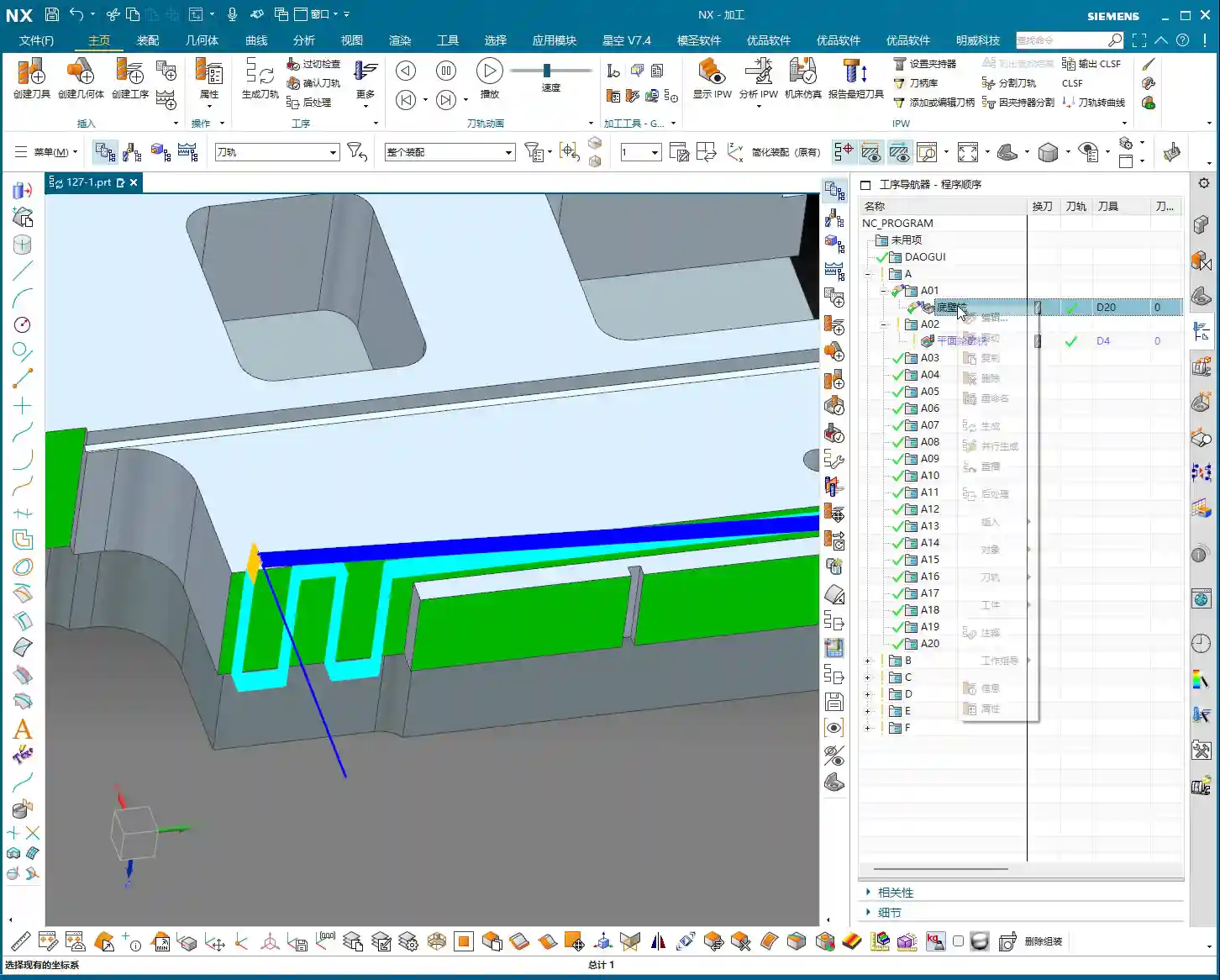
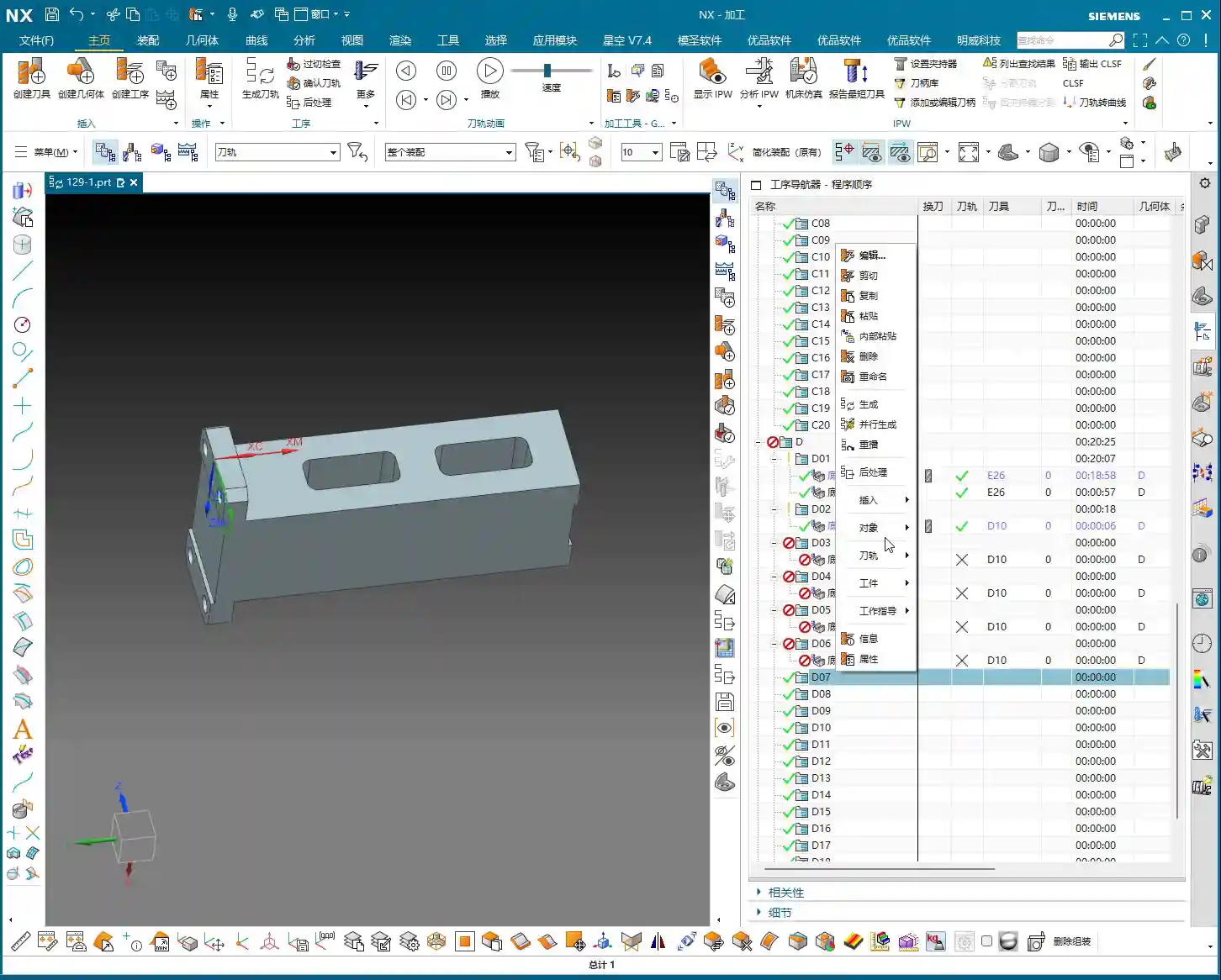
    1. Explicit Activation: Before every post-process, you must first click any operation under the specific setup (e.g., Operation A) you want to output, or directly click the parent folder of that setup itself. For instance, if you want to generate the NC program sheet for Operation A, click any toolpath within A, or click the Operation A folder.
    2. Immediate Naming: Once the NC program sheet is post-processed, immediately rename it with a clear, identifiable name. For example, for Operation A, name it A_Op.NC, and for Operation B, B_Op.NC. Don’t be lazy; otherwise, next time you won’t know which is which, and you might accidentally overwrite a file.

    Why emphasize this? Because when NX post-processes, it needs to know which machining environment is currently active, and which Work Coordinate System (WCS) and Machine Coordinate System (MCS) are in effect. If you select it, NX understands; if you don’t, it relies on ‘intuition,’ and that intuition is often wrong. It’s like in the shop: when you give a task to an apprentice, you have to clearly state which part and which face to machine, not just hand them a raw blank and expect them to figure it out, right?

    Remember this: always follow this procedure, whether it’s for A, B, C, D, or E, F, G. This workflow is a strict rule, and it guarantees efficiency and safety.

    Large Parts, Multi-Operation Setups: The Art of Paginated NC Program Sheet Output

    Selecting the Folder: The First Step to Saving Time and Effort

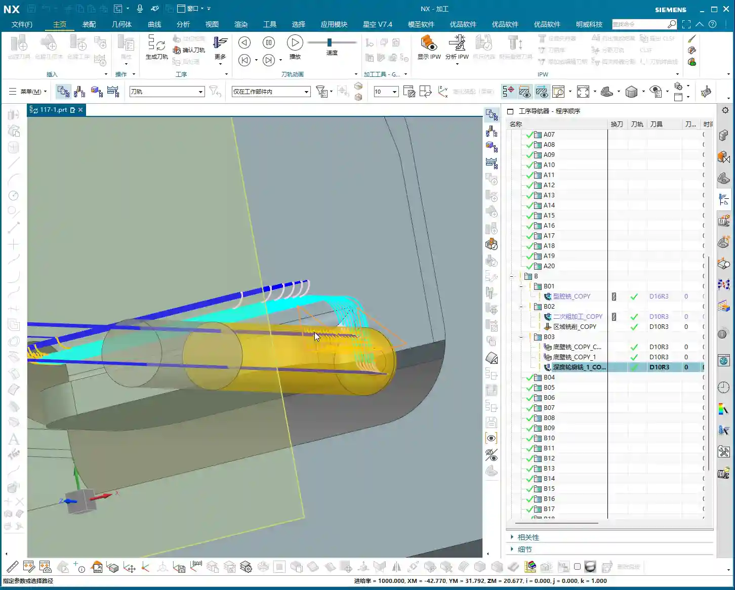
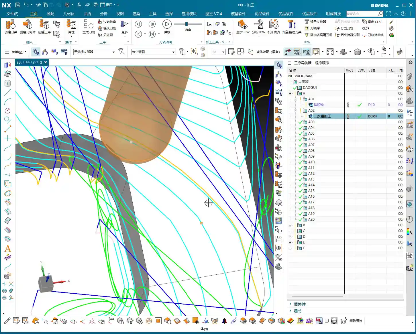
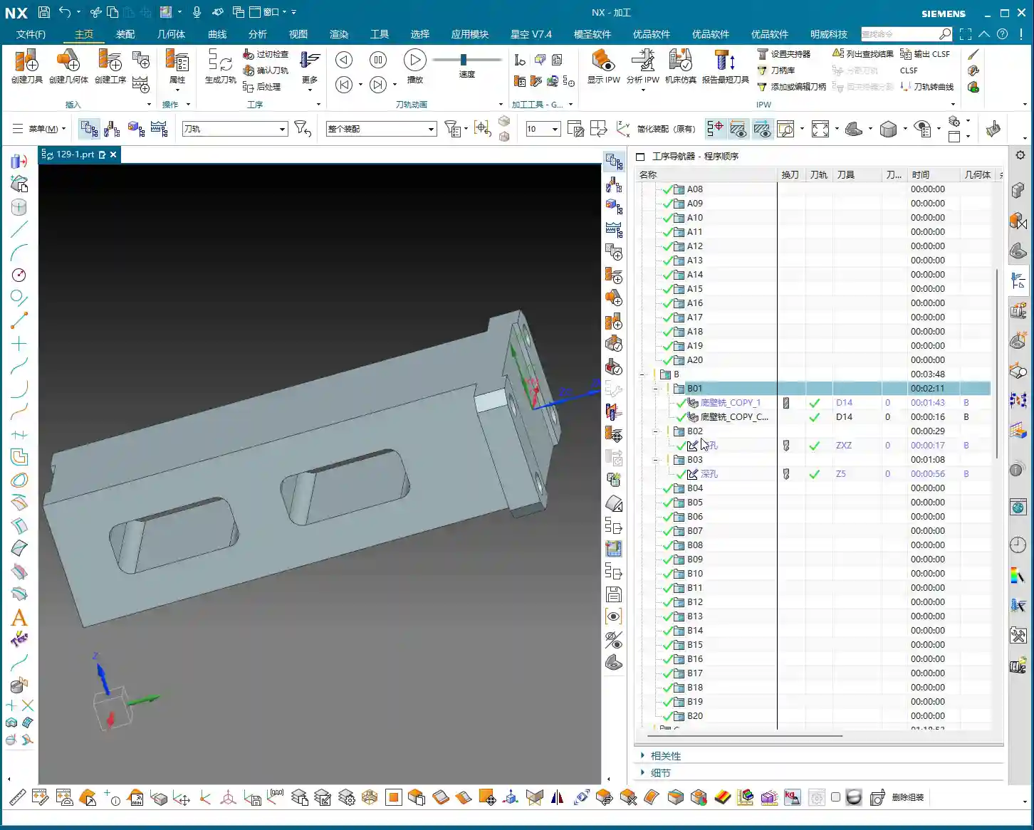
    Some colleagues have asked, ‘Master Wang, I have dozens, sometimes hundreds, of toolpath operations under a single setup. A single post-processed NC program sheet can’t contain them all, and the file becomes too long. What should I do? You can’t expect me to select them one by one, can you?’

    NC Program Sheet Too Long? Split Output is the Way to Go!

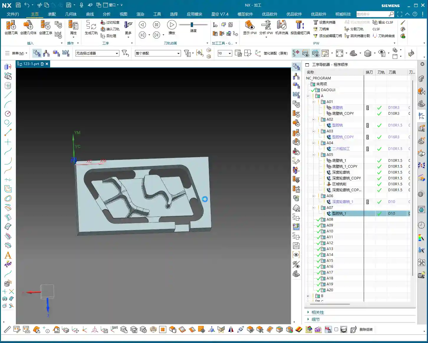
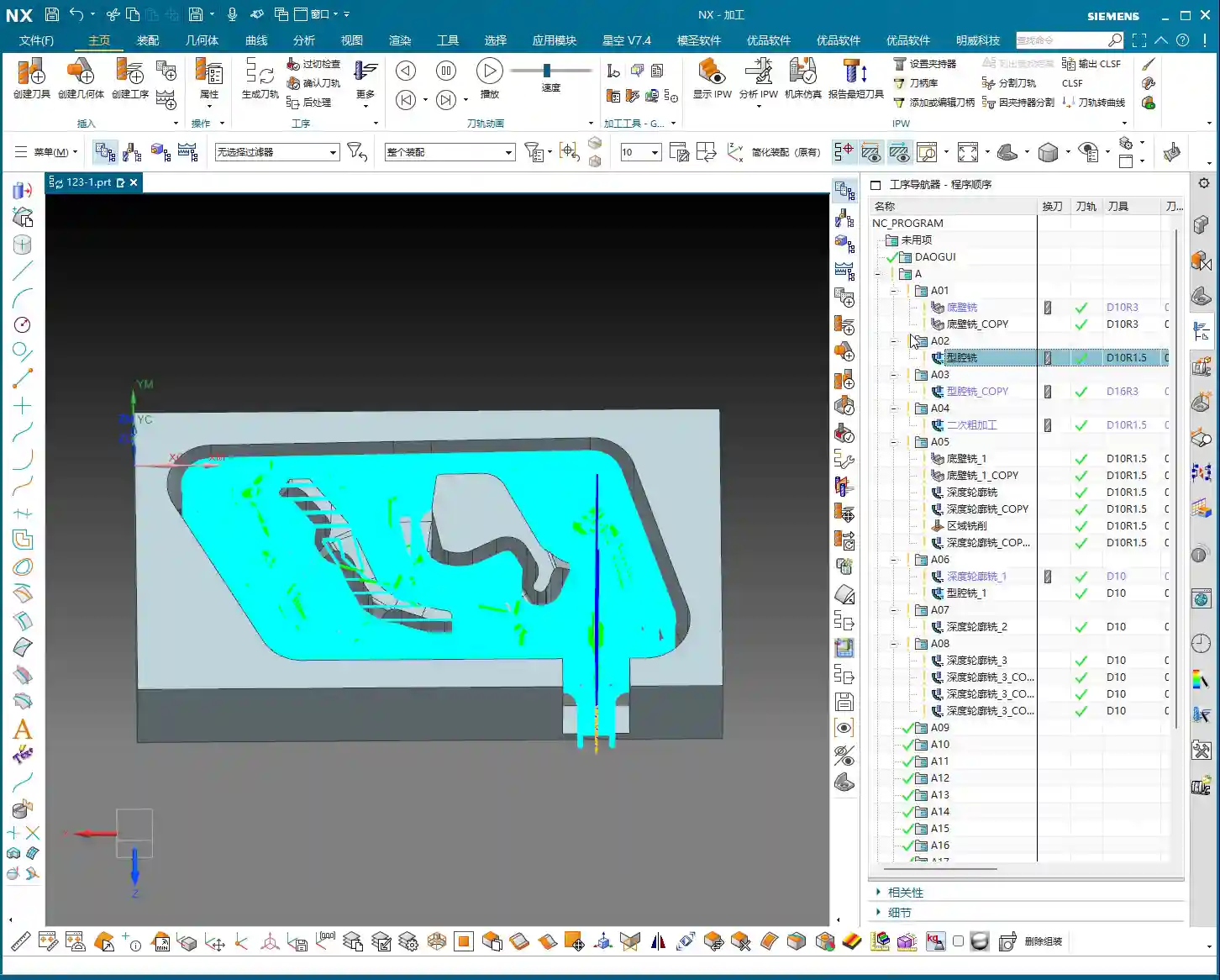
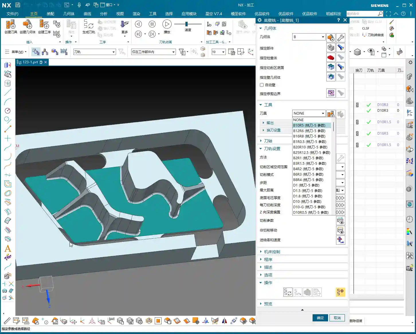
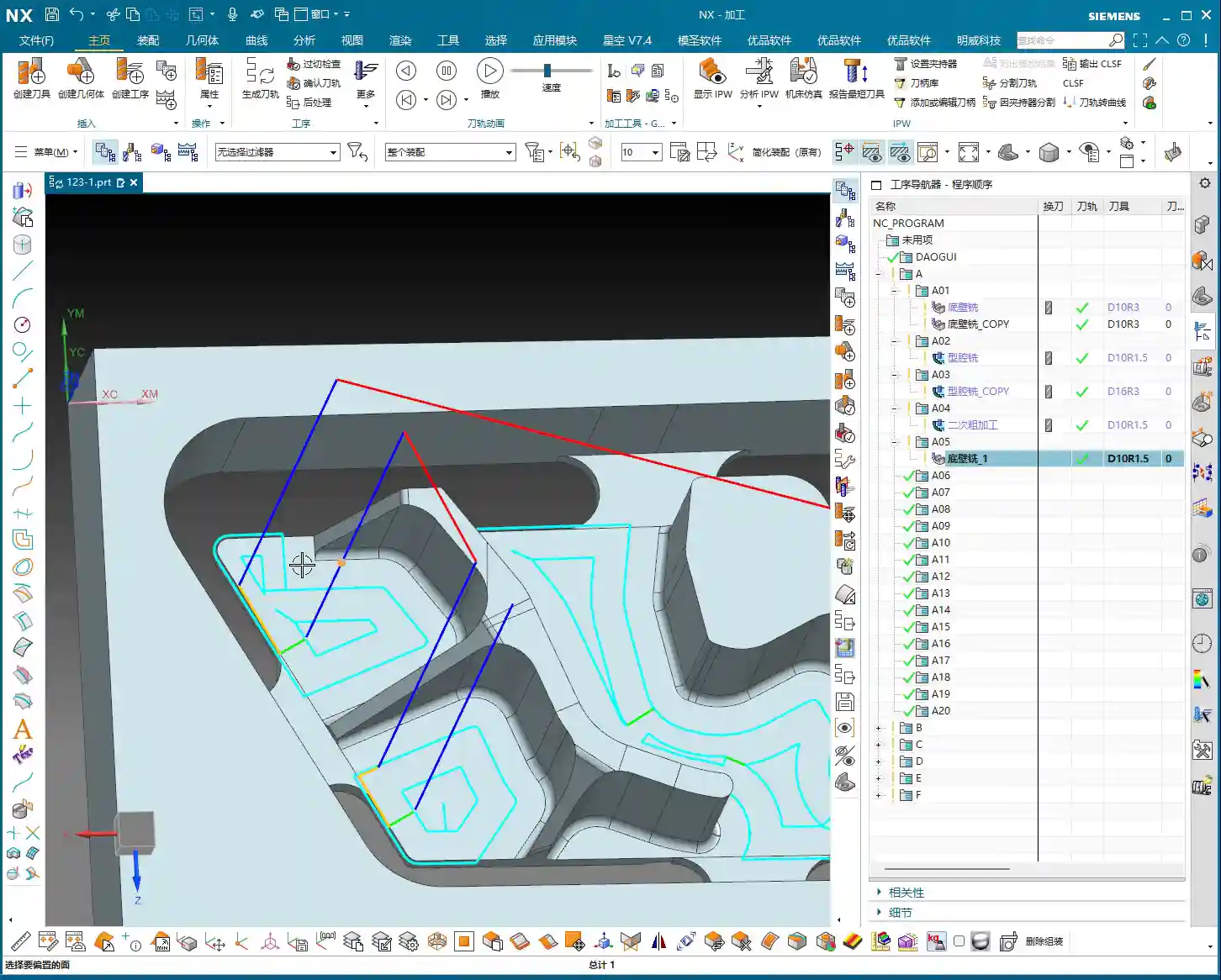
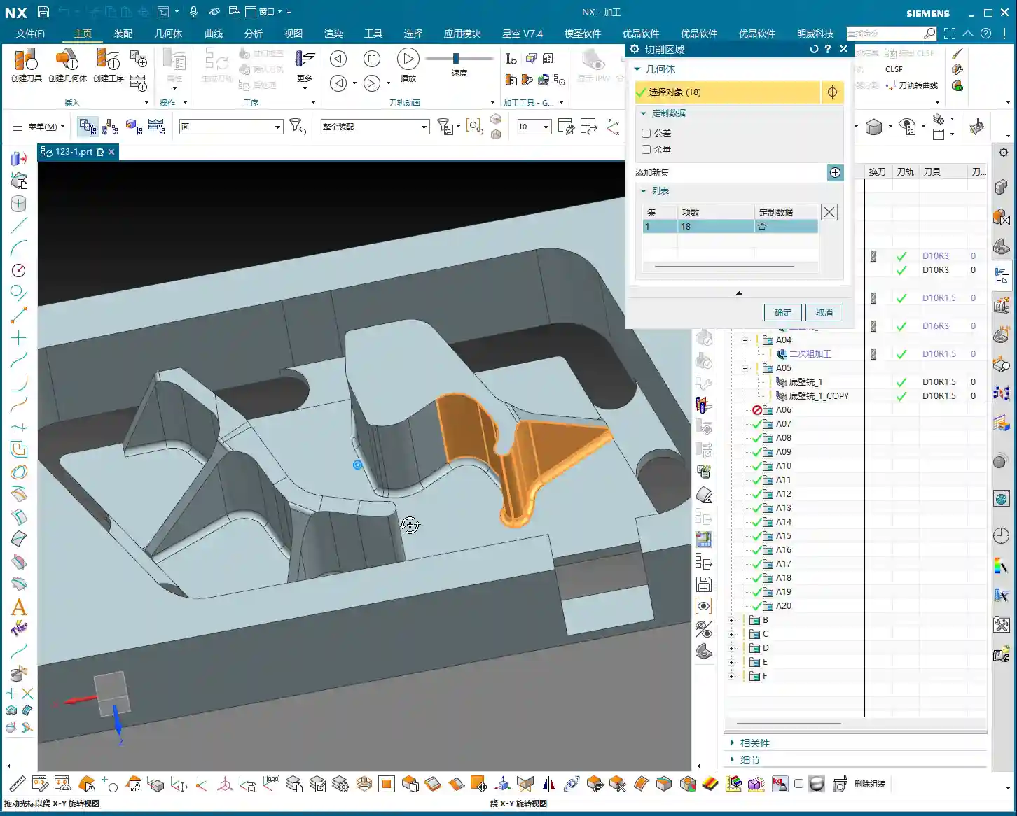
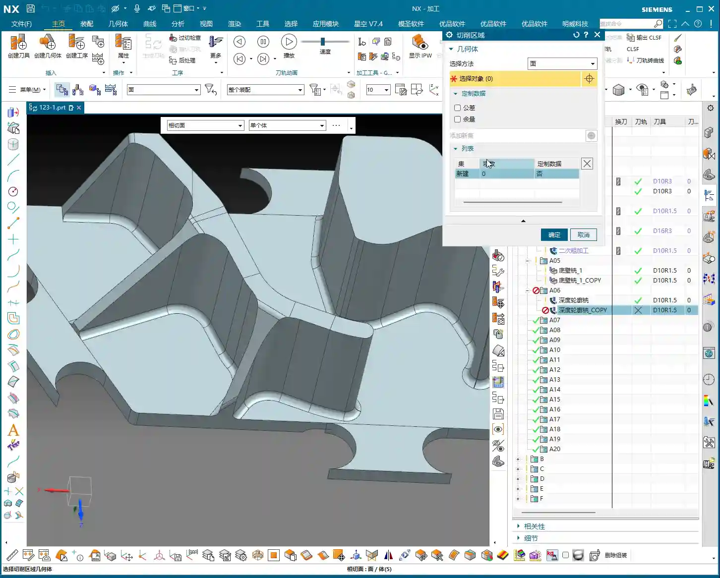
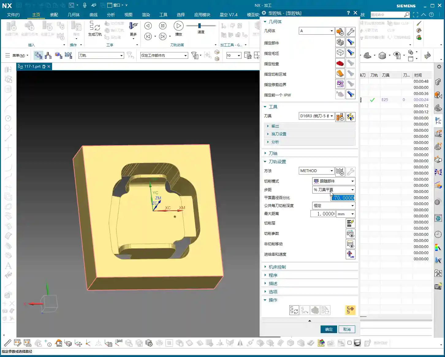
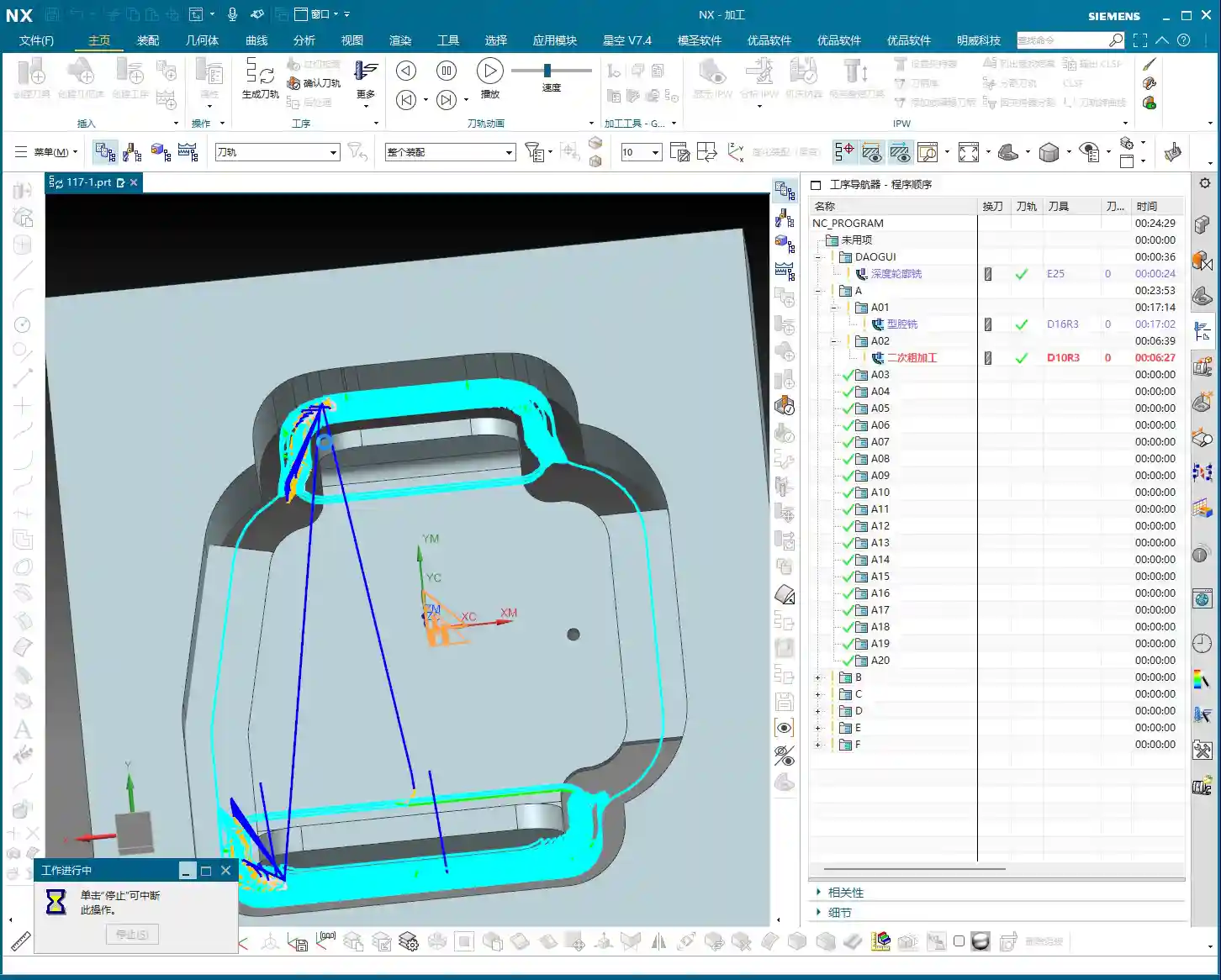
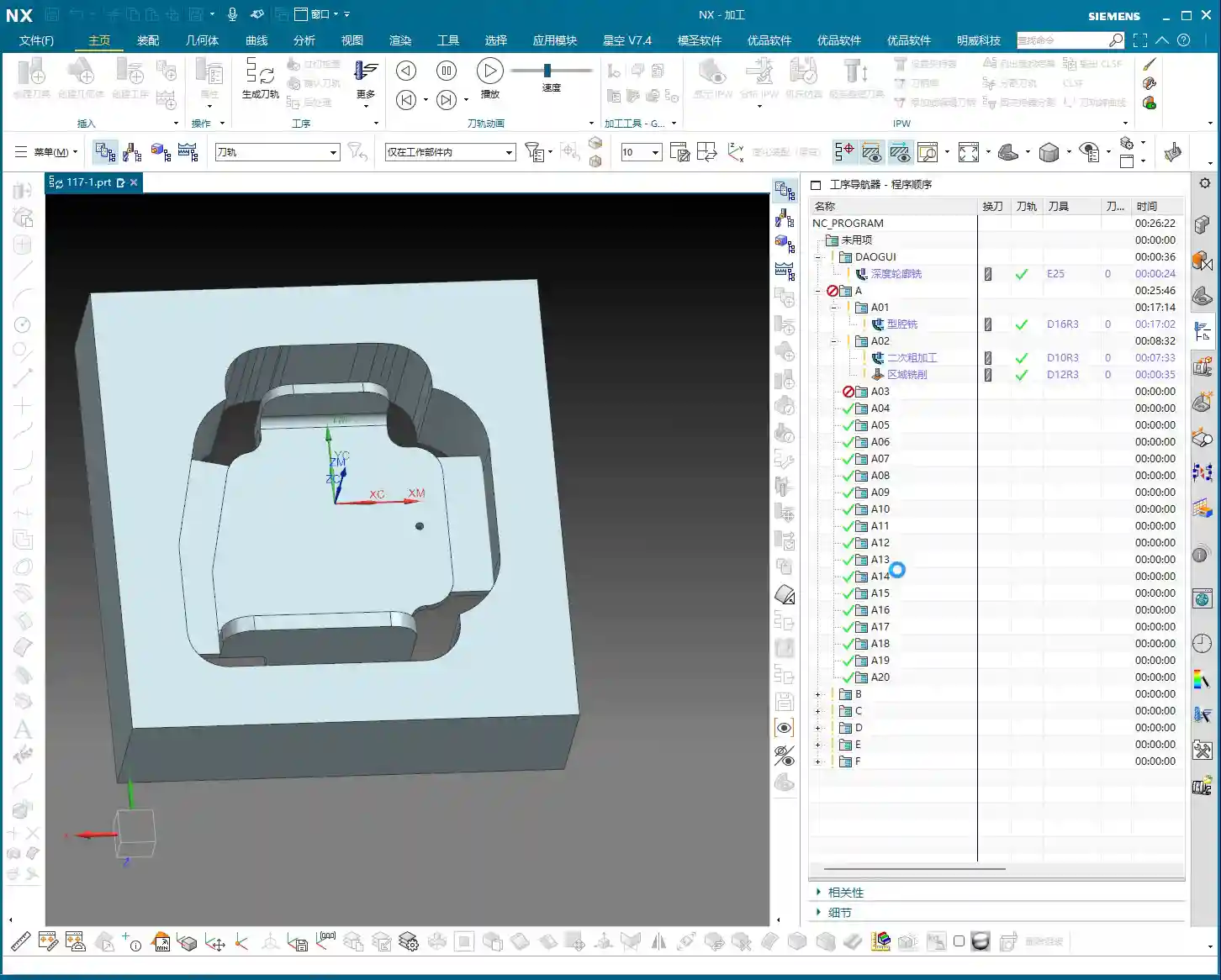
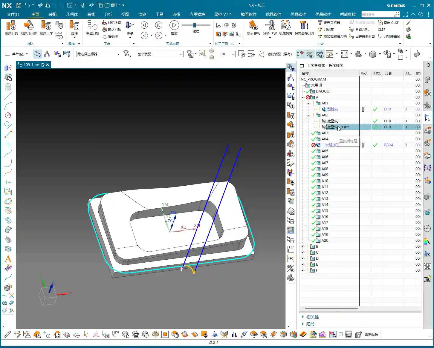
    If your setup (e.g., Operation D) contains many sub-programs (D01, D02, D03…), you don’t need to click and select each sub-program individually. You can directly select the parent folder of Operation D. The prerequisite is that you first click this Operation D folder to activate it, and then proceed with post-processing.

    This way, NX will include all toolpaths under the D folder and generate the NC program sheet for you in one go. This is much more convenient than selecting each one individually, especially when dealing with numerous programs, saving you a lot of effort.

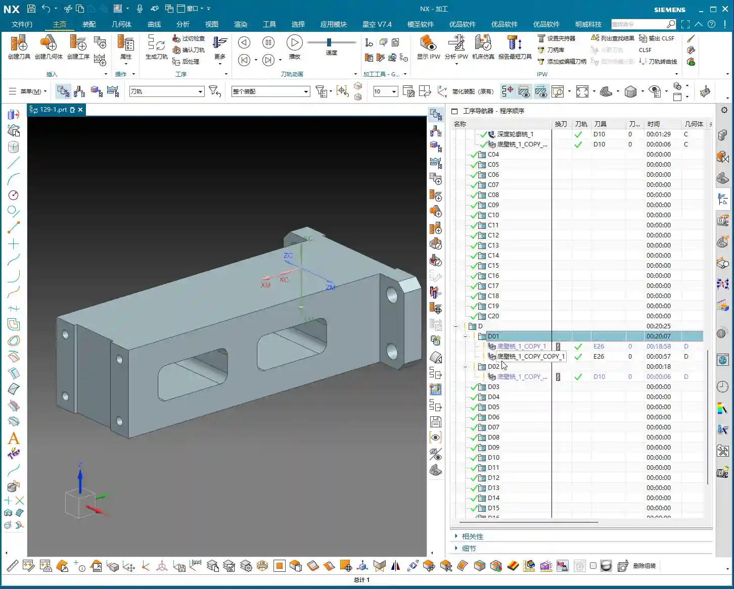
    Alright, now we face a truly tricky problem. You selected the entire Operation D folder, post-processed it, and found that the generated NC program sheet only includes operations D01 to D18 – everything from D19 onwards is missing! This happens when the NC program sheet is too long, exceeding the software’s default output limit.

    In such a scenario, don’t panic. The solution is quite simple: paginated output.

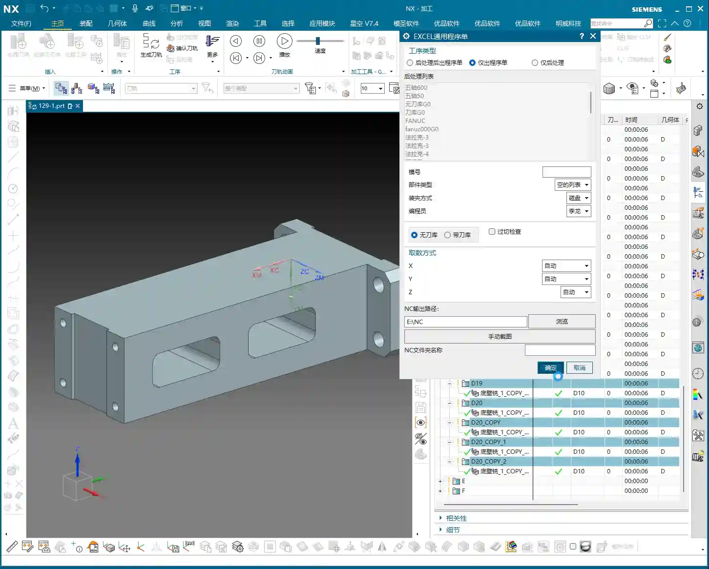
    1. First Page NC Program Sheet: The first time you post-process, it might only output D01 to D18. Save this file and name it D_Op_P1.NC (Operation D, Page 1).
    2. Second Page NC Program Sheet: Then return to NX, find Operation D19, and select D19 or its next-level subfolder. Post-process again. This time, the outputted NC program sheet will start from D19. Save this file and name it D_Op_P2.NC (Operation D, Page 2).
    3. And so on: If there are more operations yet to be outputted, continue splitting them using this method.

    You might ask, ‘Won’t the machine operator get confused with separate files?’ No, they won’t. You just need to clearly mark at the beginning of the program or on the process sheet: this setup is divided into several pages, for example, ‘Operation D: P1 (D01-D18), P2 (D19-D35).’ When the operator receives these NC program sheets, they’ll know these are continuous parts of the same setup and can execute them in sequence. I once programmed a five-axis part with front, back, left, and right faces; a single part had eight or nine pages of NC program sheets, and it was machined perfectly fine.

    Master Wang’s Advice: Details Determine Success

    These ‘unwritten rules’ are tips I’ve gathered from over a decade of hands-on experience in the workshop, encountering countless pitfalls. Though they might seem like minor procedural steps, they significantly impact actual machining efficiency and product quality. Especially in today’s era, those of us in manufacturing not only need to produce quality goods but also know how to promote our expertise. If you can concisely summarize these practical experiences, along with illustrated tutorials, and share them online, it will become your ‘gold standard’ in the industry, drawing more peers to find and trust you.

    Summary: Pitfall Avoidance Guide

    1. Mandatory Activation: Before every post-process, always click and activate the program or its parent folder that you intend to output.
    2. Immediate Renaming: After the NC program sheet is outputted, immediately rename it to prevent overwriting or confusion.
    3. Segmented Processing: When programs are excessively long, output them in segments (paginated), and clearly mark page numbers and ranges on the process sheet or in the program header.
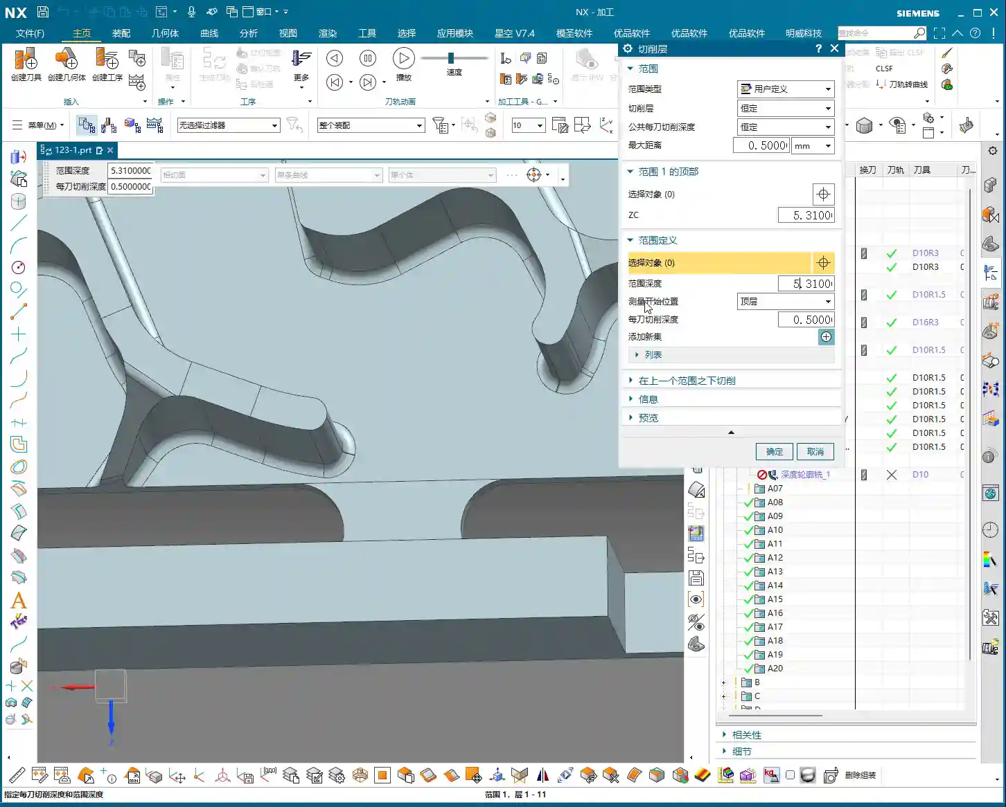
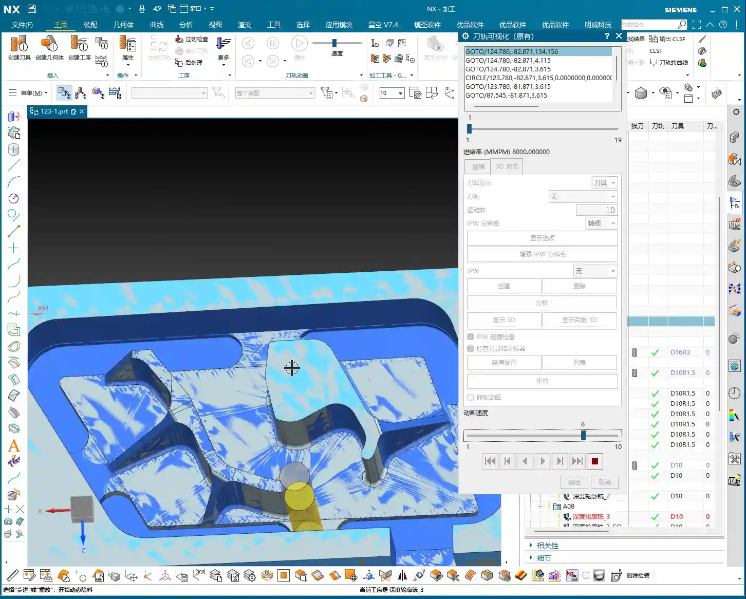
    4. Verify Coordinates: After output, quickly check if the coordinate system in the NC file is correct to prevent Work Coordinate System (WCS) / Machine Coordinate System (MCS) misalignment.
    5. Xingkong Video: For instructions on how to set up and install the Xingkong post-processor, refer to the relevant video tutorials, which provide more detailed steps.

    Alright, that concludes today’s lesson. Practice frequently, observe keenly, and always connect theory with practical application – that’s where true skill lies!

    👤 About the Author:
    The author is a veteran CNC machining professional with 15 years of industry experience, specializing in UG NX programming. This article is an original work representing personal practical insights.

    ⚠️ Copyright Notice: Unauthorized reproduction or distribution without prior communication is strictly prohibited.

  • Practical Siemens NX Side Milling Head Programming: Master Wang’s Two Tricks for Complex Groove Mach

    📝 Key Takeaways: Master Wang’s personal secrets for Siemens NX Side Milling Head programming: The core is a “two-step” strategy. A detailed explanation of Tool Axis and Clearance Plane settings to avoid chatter and unnecessary air cuts. From Coordinate System setup to Roughing and Finishing, a step-by-step guide on how to efficiently and precisely machine complex groove parts. Move beyond pure theory and address real production challenges!

    Hello everyone, I’m Master Wang. Last lesson, we thoroughly explored how to machine that workpiece below. This time, let’s dive into something more advanced – discussing 4-axis machining, specifically Side Milling Head programming.

    Introduction: The ‘Two Key Skills’ of Side Milling Head Machining

    Listen up, we’ll use this feature with a groove and specific geometry as an example, because it connects all the core technical points of the Side Milling Head. Don’t underestimate a simple groove; there’s a lot of knowledge involved.

    Coordinate System Setup: The Absolute Foundation

    Before starting any work, the first step is always to correctly set up the Work Coordinate System (WCS). This is a fundamental rule in NX programming and the lifeblood of our machining operations. If your WCS is incorrect, everything else will be pointless.

    “Once you’re in the manufacturing module, make sure the coordinate system is set. Typically, we place it above the part’s datum face (bottom face), with the machining surface as the zero point. The Z-axis zero point is the part surface itself; this ensures dimensional accuracy. Don’t slip up! I just accidentally clicked into the properties, wasting time!”

    The XYZ axis directions, especially the Z-axis, must align with your design intent and actual fixturing. This is fundamental and cannot be overlooked.

    Practical Exercise One: Roughing Techniques for Floor and Wall Milling

    Programming for a Side Milling Head isn’t vastly different from our usual 3-axis programming approach. The main distinctions lie in post-processing and the setup of a few specific parameters. Don’t rush, let’s take it step by step.

    Floor and Wall Milling Operation and Initial Toolpath Generation

    “Insert an operation; we’ll start with Floor and Wall Milling to rough out this groove feature. Let’s assume the bottom surface has already been milled, and we’re starting from the side. We’ll also assume the blank surface is flat to skip some initial preparation details.”

    Let’s measure the depth of this groove first; it’s 8 mm. Therefore, select this side face for material removal and set the machining depth accordingly. For the tool, let’s just pick one for now, say a D10 end mill. Today’s focus is how to program for the Side Milling Head; we’ll delve into tool selection later.

    “Just click generate and take a look. See that? The toolpath goes back and forth; it’s inefficient and results in a poor surface finish. This is exactly what we need to optimize!” While this back-and-forth ‘zigzag’ cutting might be acceptable in some situations, for Side Milling Head operations, especially for grooves, one-way cutting (climb or conventional milling) is the superior approach.

    There’s another issue: once the program generates, observe the approach and retract moves. They lack smooth entry and exit. This is a major no-no in actual machining; directly plunging into the material can lead to chatter or even tool breakage, and it degrades the workpiece surface quality!

    Core Secret: The ‘Two-Step’ Strategy for Side Milling Head Programming

    To program effectively for a Side Milling Head in NX, just remember these two tricks—they’re practical know-how you won’t find in textbooks.

    Trick One: The Key to Clearance Plane Setup

    “In our usual 3-axis machining, the clearance plane is always above the workpiece to prevent collisions. But with a Side Milling Head? It’s working from the side! Therefore, the Clearance Plane must change accordingly.”

    Go into the “Non-Cutting Moves” options and find “Clearance Settings”. Change the original “Automatic” or “Distance” setting to “Plane”. Then, here’s the crucial part: designate your clearance plane as the side face of the machining surface, and adjust the offset direction and distance. This way, during rapid moves, the tool will safely retract from the side instead of lifting high up and then coming back down, which both improves efficiency and prevents collision risks.

    “For operations like Floor and Wall Milling, just adjusting the clearance plane is enough, as its tool axis is by default perpendicular to the bottom face. However, for other operations like Planar Profile and Depth Profile, you’ll need to use the second trick.”

    Trick Two: Precise Control of Tool Axis Direction

    This is the essence of Side Milling Head programming! “If the Tool Axis direction is incorrect, the program simply won’t generate, or it will behave erratically if it does. Don’t just rely on software simulations; observe the cutting sparks!”

    For Side Milling Head operations other than Floor and Wall Milling, the tool axis might still default to the Z-axis direction, which is incorrect. We need to go into the “Tool Axis” settings:

    1. Select “Specify Vector”.
    2. Then choose “Fixed” or “Automatic Detection”. The most reliable method is to directly select the specific side face you intend to machine.
    3. The software will automatically adjust the tool axis direction to be perpendicular to the selected side face.

    “Once this is changed, the tool will know which direction to cut. Combined with linear approach and retract moves, for instance, using 60% of the tool diameter as the entry length, the cutting process becomes much smoother. This prevents direct tool impact on the workpiece, significantly extends tool life, and improves machining quality.”

    Practical Exercise Two: Tool Axis Adjustment for Planar Profile and Depth Profile Milling

    Alright, let’s switch locations and demonstrate again. This time, we’ll use Planar Profile and Depth Profile Milling, specifically for side walls.

    Planar Profile Milling Case Study: Tool Axis Correction and Parameter Optimization

    “Let’s measure this groove width; it’s 4 mm. So, we’ll directly use a 4 mm tool for roughing.”

    Create a new “Planar Profile” operation, select the machining boundaries, bottom face, and so on. Tool D4, generate the program directly… “See? Still no good! It’s warning again that the ‘tool axis cannot be perpendicular to the bottom face.’ This is exactly what we discussed earlier—we need to change the Tool Axis!”

    Open the “Tool Axis” settings, change it to “Specify Vector”, then select “Automatic Detection”, and finally, the crucial step: click on the side wall plane you intend to machine! “This way, the tool understands its direction is towards the side.”

    Once the tool axis is corrected, the program can generate smoothly. Don’t forget to optimize the cutting parameters:

    • Stepdown: 0.2 mm.
    • Cutting Method: Mixed Cut.
    • Stock: 0 (if this is a Finishing pass).
    • Approach/Retract: Linear approach, 60% of tool diameter, Retract is 0.

    Finally, don’t forget to also change the Clearance Plane to the side. This way, your entire Side Milling Head roughing program will be solid. If you need a Finishing pass, simply copy and paste the program, set the stock to zero, and recalculate; you’ll get it done quickly.

    Depth Profile Milling Case Study: Non-Standard Tools and Approach/Retract Optimization

    Let’s look at another example with Depth Profile Milling. “I measured this area, and it has a dimension of 10.1 mm. This isn’t a standard tool size! We can only use a D10 tool, leaving a small amount of stock, and then follow up with a Finishing pass.” This is a practical situation in production—you can’t just customize a tool for every non-standard dimension, can you? The cost won’t allow it!

    For the operation, select “Depth Profile Milling” and for the cutting method, choose “Center” (which makes the tool center follow the boundary). With the initial settings, the tool axis is still Z-directional, and the program won’t generate. “It’s the Tool Axis problem again! Same old issue.”

    Just like before, change the tool axis to “Specify Vector”, select “Automatic Detection”, and then click on the side wall plane. The program will then generate normally.

    Then, for optimization:

    • Cutting Method: Mixed Cut, for a more even toolpath.
    • Approach/Retract: Linear, 60% of tool diameter, Retract is 0.
    • Stock: 0.05 mm (to leave material for Finishing pass).

    Finally, check and set the Clearance Plane, ensuring it’s on the side. With that, your Depth Profile Milling program is also sorted.

    Summary: Pitfall Avoidance Guide

    Alright folks, listen up! The core of Side Milling Head programming boils down to these two points. Master them, and you’ll save a lot of detours and prevent many tool crashes:

    1. Tool Axis Direction: This is the soul of Side Milling Head programming. Except for a few operations like Floor and Wall Milling where the tool axis is automatically determined, for any other side machining operation, you must manually specify the tool axis direction. Select “Specify Vector,” then click on the side face you are actually machining, so the tool cuts perpendicular to that face. This is crucial for preventing the tool from “crashing into the wall”!
    2. Clearance Plane: A Side Milling Head operates from the side, so its clearance plane should also be on the side. In “Non-Cutting Moves,” ensure you change the clearance settings to “Plane” and designate a side face parallel to the machining surface as the clearance plane. This allows the tool to safely approach and retract, avoiding unnecessary lifts and air cuts, thereby boosting overall machining efficiency.
    3. Approach/Retract Settings: To ensure stable cutting and extend tool life, always set the approach and retract moves to linear or arc transitions. Also, set an appropriate entry distance (e.g., 60% of the tool diameter) to prevent the tool from directly impacting the workpiece.
    4. Handling Non-Standard Dimensions: When encountering non-standard dimensions like 10.1 mm, don’t think about customizing a tool. Prioritize using a nearby standard tool (e.g., D10), and resolve the issue by leaving stock and performing a secondary Finishing pass. This is the most cost-effective approach.

    Remember these practical tips, and you’ll get fewer reprimands and produce more in the workshop! Don’t just rely on software simulations; go to the machine, observe the cutting sparks, and listen to the cutting sounds – that’s where the real skill lies!

    👤 About the Author:
    The author is a veteran CNC machining professional with 15 years of industry experience, specializing in UG NX programming. This article is an original work representing personal practical insights.

    ⚠️ Copyright Notice: Unauthorized reproduction or distribution without prior communication is strictly prohibited.

  • Master Wang’s Siemens NX Real-world Case: Master Complex Rib Programming with a Three-Stage Process

    📝 Key Takeaways:

    NX Complex Rib Programming: A Practical Deep Dive into a Three-Stage Process

    Alright, Listen Up, Lads! Master Wang Teaches You Three Tricks to Ace Rib Machining

    Today, we’re not talking theory; we’re getting straight to the practical insights. All that theory you learned in school often leaves you stumped on the shop floor, especially with parts like these ribs that demand both strength and precision. Don’t worry. Today, Master Wang will walk you through this case study, showing you how to program efficient and precise toolpaths using Siemens NX. Remember, machining isn’t just theory; it’s about watching the cutting sparks and listening to the machine!

    Don’t let the simple structure of these ribs fool you; they’re often the backbone of a part, demanding high strength and precision. Especially those small fillets and chamfers at the connections—mishandle them, and you’ll either compromise assembly or create stress concentrations, leading to immediate scrap. That’s why Master Wang has put together a “Three-Stage” programming method that’s guaranteed to be effective and immediately applicable!

    Stage One: Rib Side Wall Roughing / Semi-Finishing – “Aggressive Yet Controlled, Step by Step”

    This is the first, and most crucial, step. The side walls of the rib are often the primary load-bearing surfaces and must be smooth and flat. We need to start with a larger tool to Contour Mill out the basic shape.

    Core Operation: Cleverly Use Surface Milling, Avoid Ball End Mill Pitfalls

    Listen up, here we’re using “Surface Milling”. Why Surface Milling? Because it’s highly adaptable to complex surfaces, creating smoother toolpaths and uniform cutting forces. Some novices see a sloped surface and immediately think of using a ball end mill – a huge mistake! When machining side walls with a ball end mill, the cutting action occurs at the tool’s bottom, leading to low cutting efficiency and prone to Chatter. Especially when the bottom fillet hasn’t been cleared yet, a ball end mill simply can’t reach, failing to “Contour Mill to the bottom surface.”

    • Tool Selection: I typically choose a D12R1.5 (diameter 12mm, 1.5mm corner radius) flat end mill with a radius. Don’t underestimate this corner radius; it significantly boosts tool strength, preventing chipping at the tip, and also simplifies Corner Cleanup in subsequent operations.
    • Infeed and Cutting Parameters:

      • Depth of Cut: If it’s aluminum, you can go with a 0.15mm Stepdown per pass. Don’t get greedy; we’re not chasing speed, we’re laying the groundwork for the Finishing pass.
      • Cutting Pattern: Use “Zigzag” to reduce retracts and improve efficiency.
      • Stock Allowance Control: Leave 0.2mm on the side walls and 0.3mm on the bottom surface. These allowances are for subsequent Finishing passes and Corner Cleanup; don’t machine them all off in one go.
      • Boundary Selection: Precisely select the side wall surfaces to be machined. As for those small fillets, leave them for now; we’ll tackle them in Stage Two.

    Master Wang’s Tip: Software simulations look great, but ultimately, it comes down to the cutting sparks and sound from the machine. If the sound is dull, it indicates excessive cutting force, possibly due to too fast a feed rate or too large a Depth of Cut – you need to adjust it! Excessive sparks suggest tool wear, which also needs attention.

    Stage Two: Cavity Roughing and Local Finishing – “Progressive Refinement, Fine Detailing”

    Stage One covered the main outline of the rib. Now it’s time to tackle the hidden cavities and fillets, which are critical for precision and surface quality.

    Core Operation: Utilize Deep Contour Milling and Cavity Milling Concurrently for Thorough Fillet Cleanup

    This stage consists of two parts: roughing first, then finishing, with targeted strategies.

    • Cavity Roughing (Main Area):

      • Operation Type: We’ll use “Cavity Milling for Roughing”. For material removal in the areas beneath the rib or the main body, cavity milling offers the highest efficiency.
      • Tool Selection: You can still use the previous D12R1.5 tool, or switch to a larger diameter tool depending on the cavity size.
      • Cutting Parameters: Use a 0.5mm Depth of Cut per pass, a side wall allowance of 0.1mm, and set the bottom allowance to 0 this time (as it’s managed internally by the cutting levels), ensuring thorough roughing without overcutting.
      • Depth Control: Start from the top surface of the rib and mill down to the final bottom surface. Remember to leave a 0.1mm machining allowance to prevent milling into the workholding table and to provide room for the Finishing pass.

    • Local Fillet Finishing (Corner Cleanup):

      • Operation Type: The core operation is “Deep Contour Milling”, specifically for Corner Cleanup. It performs multi-level cutting along the part’s contour, making it ideal for internal radii.
      • Tool Selection: Switch to a smaller ball-nose end mill, for instance, a D6R0.5 or D4R0.2. Determine this based on the minimum fillet radius of the rib; the tool diameter must be less than or equal to the minimum fillet diameter.
      • Cutting Parameters: Use a 0.5mm Depth of Cut to ensure stable cutting. Most importantly, precisely control the start and end surfaces, beginning from the bottom surface of the rib, adding the fillet radius as the start height, and milling to the target height.
      • Allowance: Set both side wall and bottom allowances to 0; this pass is about milling it precisely to size, ensuring thorough Corner Cleanup.

    Master Wang’s Tip: When using Deep Contour Milling in complex areas, you might sometimes encounter “Chatter” or “tool skipping” phenomena. If this happens, try reducing the feed rate or adjusting the cutting strategy, for example, from “Conventional” to “Climb Milling.” Don’t be afraid to go slow; stability and precision are paramount.

    Stage Three: Contour Finishing and Final Cut-Off – “A Single Pass for Perfection, The Grand Finale”

    The first two stages have largely taken care of the rib’s forms and internal features. This final stage is about giving the part its “outer finish” and cleanly “liberating” it from the raw stock.

    Core Operation: Smooth Side Walls, Precise Cut-Off, Leave a “Tab”

    This step is crucial for the final surface quality and the integrity of the part; don’t mess it up.

    • Rib Side Wall Finishing Pass (Smooth Side Walls):

      • Operation Type: Continue using “Deep Contour Milling”, as it allows for a precise Finishing pass across the entire side wall, ensuring surface finish.
      • Tool Selection: We’ll use a D10R0.5 ball-nose end mill to ensure the required surface roughness.
      • Cutting Parameters: Use a 1-2mm Depth of Cut, or even go full depth in one pass, to achieve the best surface finish. From the top surface to the bottom, control the final depth by subtracting a 0.7mm allowance.
      • Allowance: Set both side wall and bottom allowances to 0; this is the final Finishing pass, so no more allowance should be left.

    • Final Contour Cut-Off:

      • Operation Type: We’ll still use “Deep Contour Milling”, but this time, it’s to cut the part free.
      • Tool Selection: Continue with the D10R0.5 or a D10 flat end mill, depending on the requirements for the cut-off surface.
      • Cutting Parameters: Use a 0.2mm Depth of Cut, follow the outer contour, and ensure the cutting depth penetrates the part, but be careful not to cut into the Fixturing.
      • Cut-Off Allowance: Here’s the most important part: leave a 0.5mm connection (or even smaller) at the bottom for easy manual break-off or wire EDM later. This is called a “tab”; don’t cut through it completely, or the part will drop, potentially getting dinged or seriously damaged.

    Master Wang’s Tip: For this cut-off step, once the program is ready, be sure to carefully inspect the toolpath on the machine, especially the safety clearance between the tool and the Fixturing. Don’t let the tool hit the Fixturing before it even touches the part – that’s more than a minor issue!

    Summary: Pitfall Avoidance Guide

    • Tool Selection Pitfalls: Don’t always try to use one tool for the entire job. Use larger tools for Roughing, and smaller tools for Finishing passes and Corner Cleanup. Flat end mills, radius end mills, and ball end mills each have their strengths; choose flexibly based on the geometry of the machining area, don’t cut corners.
    • Stock Allowance Control Errors: Leave sufficient allowance for Roughing, and gradually reduce it for Finishing passes. Incorrect allowance can lead to rapid tool wear or failure to meet surface requirements. Especially during cut-off, always leave a “tab” at the bottom to secure the part.
    • Blind Cutting Parameter Selection: Feed rate, spindle speed, Depth of Cut – these parameters aren’t just memorized; they’re determined by a combination of material, tool, machine rigidity, and your desired outcome. Observe the cutting conditions, listen to the sounds, and accumulate experience.
    • Software Simulation Dependence: Even the most realistic Siemens NX simulation is still just a “simulation.” In actual operation, machine vibration, tool wear, and workpiece deformation can all lead to errors. Therefore, for every new program on the machine, run the first part slowly, observing and adjusting as you go – that’s the golden rule.
    • Neglecting Precision Errors: If part precision isn’t met, don’t just blame the machine. Master Wang can “grind out” a ±0.005mm error by adjusting process compensation and toolpath strategies. This requires you to have an intimate understanding of the machine’s geometric errors, thermal deformation, and tool runout.
    • Weak Cost Awareness: When programming, always think about cost and efficiency. Unnecessary air cuts, excessively long toolpaths, and too many tool changes all increase machining time and raise costs. Optimizing toolpaths, minimizing air cuts, and boosting single-tool efficiency are hallmarks of high-level programming.

    Alright, that’s all for today. These are genuine skills Master Wang has honed over fifteen years of hands-on experience – you won’t learn them from textbooks! Digest this well, and next time you encounter ribs, you’ll know exactly how to approach the cut. Remember, in our line of work, experience is the best teacher, and practical application is the only truth!

    👤 About the Author:
    The author is a veteran CNC machining professional with 15 years of industry experience, specializing in UG NX programming. This article is an original work representing personal practical insights.

    ⚠️ Copyright Notice: Unauthorized reproduction or distribution without prior communication is strictly prohibited.

  • Siemens NX Programming in Practice: Second Operation Finishing of Connecting Ribs – High-Precision S

    📝 Key Takeaways: Master Wang provides hands-on instruction in practical Siemens NX programming for the second operation of connecting ribs. He details sidewall stock allowance settings, bottom surface finishing strategies, and optimization of R1.5 tool parameters. Emphasized practical techniques include manual face selection and toolpath extension, ensuring high precision and efficiency while bridging the gap between theory and practice.

    Hello everyone, this is Master Wang. Today, we’re continuing our discussion on machining connecting ribs. Last time, we covered roughing; this time, the focus is on **second operation finishing**. Our main goal is to precisely finish the sidewalls and bottom surfaces, preparing the part for subsequent cutoff operations. Pay close attention, because this isn’t just about clicking a mouse; there are many critical details involved.

    Second Operation Preparation: Sidewall Stock Allowance and Corner Radius Specifics

    In previous programming, some areas of the sidewalls might not have had any stock allowance left, perhaps for efficiency. However, for this finishing step, especially when performing **corner cleanup**, you can’t be so casual. Here, I need to correct a common misconception.

    Why Leave Stock Allowance on Sidewalls?

    I heard in the audio that previously, we considered leaving no stock allowance on the sidewalls. But now, we’re going to re-add a **0.01mm** stock allowance. You might be asking, ‘Master Wang, isn’t that redundant?’ Don’t rush to judgment; let me explain:

    • **Corner Cleanup Considerations:** Look, there will definitely be small corner radii on the edges of this connecting rib. We’ll be using a **D10 tool** later for **corner cleanup** on these edges. If no stock allowance is left on the sidewall, two situations can easily arise when the D10 tool comes down: either it hits the corner radius and overcuts it, or it can’t fully clean down to the root, leaving a ‘burr’ or ‘ridge’.
    • **Ensuring Toolpath Integrity:** Leaving a **0.01mm** stock allowance provides sufficient clearance for the D10 tool. When it performs corner cleanup, the sidewall won’t be ‘eaten into’ by the tool, and the corner radius will be perfectly machined. Once this step is complete, a subsequent **finishing pass** can remove this **0.01mm**, significantly improving part accuracy. This is a practical trick you won’t find in textbooks.

    Bottom Surface Semi-Finishing / Finishing: Toolpath and Parameter Fine-Tuning

    With the sidewalls clarified, let’s address the bottom surface. This area cannot be overlooked, as it directly impacts the overall flatness of the part.

    Bottom Surface Program Creation and Entry Strategy

    Insert a new program, focusing on the bottom surface first. When selecting faces, make sure to select all bottom surfaces. For the entry strategy, since the sidewalls have already been machined, we can consider **entering from outside the part**. This way, the tool doesn’t have to struggle to plunge into the material, resulting in smoother cutting and extended tool life.

    Tool and Machining Parameter Settings

    For bottom surface machining, I recommend using an **R1.5 ball end mill** (or a flat end mill with a corner radius, depending on specific requirements).

    • **Depth of Cut (Stepdown):** This parameter is crucial, directly affecting surface quality and machining efficiency. I heard you set it to **0.1mm**. This is very fine, suitable for **finishing passes**. For **roughing**, you would need to increase it.
    • **Stepover:** Set this to **percentage stepover**, with the direction **inward**. This causes the toolpath to progress from outside to inside, layer by layer, resulting in more stable cutting.
    • **Angle Adjustment:** If the tool’s movement appears to ‘turn too much,’ you’ll need to adjust the angle. Elevate it slightly to allow the tool to move more freely, avoiding unnecessary cutting trajectories.
    • **Clearance Distance and Retract Height:** Let’s change the **clearance distance** to **0.5mm**. Also, a critical point: the stock allowance and retract height you mentioned earlier are mismatched; they need correction! Re-set the **sidewall stock allowance** to **0** so the tool doesn’t leave marks on the sidewall. The retract height should also be changed to **1mm** to ensure safety without retracting too high and wasting time.

    Sidewall Finishing Pass: Avoiding Tangency Surface Traps

    With the bottom surface addressed, let’s return to thoroughly finish the sidewalls. The most common pitfall in this step is **face selection**, especially for complex faces with tangency relationships.

    How to Precisely Select Sidewall Faces

    You mentioned that if certain sidewall areas are incorrectly or poorly selected, problems will arise. This is especially true for **tangent faces**, where automatic software selection can easily include faces that shouldn’t be machined, causing more trouble. In such cases, **manual intervention** is essential!

    • **Better Manual than Incorrect:** If the software’s automatic face selection isn’t reliable, then select them **one by one!** Don’t be afraid of the hassle; a few minutes spent now is insignificant compared to reworking or scrapping a part. Accurately select all sidewall faces that require a finish cut.
    • **Toolpath Trimming:** Remember, in some areas, if you let the tool run freely, it will generate redundant toolpaths, or even cause a **tool crash**. Therefore, you must **trim the toolpath**. Directly ‘cut’ away areas that don’t require machining, or where interference might occur, to ensure a clean and safe toolpath.

    Coordinating Subsequent Bottom Surface and Sidewall Finishing Passes

    We can duplicate the bottom surface **finishing pass** program, change the stock allowance to **0**, and let it completely finish the bottom surface. Then, perform another **finishing pass** on the sidewalls. For this sidewall **finishing pass**, continue to use the **D10R1.5 tool**, with a **1mm depth of cut** per pass. The goal is to allow the tool to finish all the way down to the bottom surface.

    • **Corner Radius Machining:** When encountering the small corner radii that were previously allowed for, you can adjust the corner radius parameter to **1.5mm** (or as per actual requirements). This step ensures smooth corner transitions, no burrs, and accurate dimensions.
    • **Safe Entry:** Tool entry must be safe; ideally, the tool should enter along the edge of the workpiece. This prevents interference and ensures machining stability.

    Toolpath Optimization: Practical Wisdom on Retracts and Extensions

    After finishing and generating the program, don’t rush to the machine. You still need to review the toolpath for any necessary optimizations; these are key factors affecting efficiency and final quality.

    Rational Setting of Retract Height

    You mentioned that the **retract height** is too high. This is a common issue! High **retracts** are purely a waste of time. Let’s change it to a **plane retract**, setting the **clearance distance** to **10mm** (or based on actual conditions, such as 5-10mm above the highest point of the workpiece). Remember, as long as it ensures no **tool crash**, keep the **retract height** as low as possible. Every second saved adds up; that’s how you gain efficiency!

    The Necessity of Toolpath Extension

    Another small detail is **toolpath extension**. Often, if you don’t extend the toolpath slightly, for example, by **0.3mm or 0.5mm**, it’s easy to leave a tiny unprocessed area at the end of the tool’s path. Don’t underestimate these few tenths of a millimeter; they can affect the entire surface finish and even lead to out-of-spec dimensions. So, when this happens, directly extend the toolpath slightly to ensure the tool fully cuts off the workpiece and completely cleans the area.

    Balancing Efficiency and Tool Life

    Finally, let’s talk about efficiency. For sidewall **finishing passes**, if you find a **1mm depth of cut** too slow and the stock allowance is relatively large, you can certainly take more passes, reduce the **depth of cut** per pass, and increase the feed rate. These adjustments are always based on actual conditions; there are no rigid, one-size-fits-all rules. Our goal is to maximize efficiency and minimize tool wear while maintaining quality. That’s how you make money, understand?

    Summary: Pitfall Avoidance Guide

    • **Precise Stock Allowance Settings:** Don’t assume no stock allowance means it’s finished. Sometimes, leaving a minute allowance (e.g., **0.01mm**) can save significant trouble for subsequent **corner cleanup** and ensuring accuracy.
    • **No Laziness in Manual Face Selection:** When dealing with complex **tangent faces** and automatic software selection is unreliable, decisively switch to **manual face selection**, picking them one by one to ensure foolproof results.
    • **Toolpath Trimming is Essential:** Promptly trim redundant or risky toolpaths to prevent **tool crashes** and inefficient cutting.
    • **Rational Retract Height:** While ensuring safety, minimize **retract height** as much as possible. These small savings add up, improving overall machining efficiency.
    • **Toolpath Extension Prevents Uncut Areas:** For critical toolpath regions, remember to extend them appropriately to eliminate any unprocessed ‘dead spots’.
    • **Parameter Adjustment Based on Observation:** No matter how good the software simulation looks, ultimately you must observe the **cutting sparks** and the actual workpiece condition, flexibly adjusting parameters based on experience.

    👤 About the Author:
    The author is a veteran CNC machining professional with 15 years of industry experience, specializing in UG NX programming. This article is an original work representing personal practical insights.

    ⚠️ Copyright Notice: Unauthorized reproduction or distribution without prior communication is strictly prohibited.

  • Siemens NX Programming in Practice: Detailed 2nd Operation for Efficient Rib Machining – Master Wang

    📝 Key Takeaways:

    Practical Rib Machining (2nd Operation): Master Wang’s Guide to Siemens NX Programming & Optimization

    First Step: Workpiece Coordinate System (WCS) B-Side Adjustment and Datum Definition

    Hello everyone, this is Master Wang. In the last lesson, we discussed machining the front side of the connecting ribs. Today, we’ll continue and tackle the back side of this part, which is the second operation (Op 2). Listen up, this area isn’t simpler than the front; there are plenty of crucial details.

    For the back side machining, the first step is to modify the Work Coordinate System. Simply change the primary Machine Coordinate System (MCS). To put it simply, select the B-side. Double-click the WCS and adjust the Z-axis direction to ensure it points towards the back side we intend to machine. Sometimes, when I’m too quick, I might place the origin in the middle, but that’s a no-go. This job demands high precision, so the origin must be placed at the designated location, like our datum corner, not just anywhere. One slip-up, and the tool will cut into the part.

    Remember, whether it’s the A-side or B-side, as long as the Z-axis direction is correct, the program won’t show errors (turn red); this is fundamental Siemens NX logic. But don’t even think about double-clicking and directly modifying an A-side program to run on the B-side; that program will definitely error out and turn red! That operation is absolutely incorrect. As long as we ensure the J-axis points upwards, milling can commence from either side.

    We also need to thoroughly check the datum points for the B-side, ensuring they correspond with the A-side datum points, both being at the same location. If the front’s datum is zero, then conversely, the back’s datum should also be zero. These finer points aren’t necessarily taught in textbooks.

    Roughing Strategy: Rib Side Roughing and Stock Allowance

    Rib Side Roughing Toolpath Optimization

    Next is the **roughing** of the rib’s side. We need to **rough** out this area. Here’s a critical consideration: Is it better to **rough** everything out, or to **rough** to a certain face first, and then perform a **finishing pass**?

    In my experience, for connecting ribs like these, especially if they are connected on both sides, we can start by only **roughing** down to this specific face. Once this area is **roughed** out, meaning the initial **Rest Milling** is complete, we then proceed with a Finishing pass. After the **finishing pass**, we perform another **roughing** operation, either a secondary **roughing** or semi-**finishing** mill. This staged approach can effectively reduce machining stress, which is paramount for preventing deformation, especially with materials like titanium alloys and high-temperature nickel-based alloys.

    Therefore, we’ll first **rough** this face. Select the final face to ensure our **roughing** range is correct. Then, change the program mode from automatic to manual face selection. This allows for precise control of the machining area, preventing air cutting or milling into unintended regions.

    Program Duplication and Parameter Adjustment Pitfalls

    The programming method for the other side (front) is essentially the same as for this (back) side, so we can directly duplicate the previous roughing program. After duplicating, remember to change the WCS to the B-side, and then use Teach Geometry to control the toolpath. This will save a significant amount of time.

    Oh, right, I think I selected the wrong tool earlier when programming the other side. You might have noticed. My apologies, I was a bit too quick! Let’s re-select; we should be using an R10 or R12.5 tool (the audio mentioned 12R3, then 10, then 12; I understand this as various options, ultimately choosing the most suitable). That’s how it is when you’re working—if you make a mistake, you fix it; don’t just power through it!

    Once we finish programming, we *must* check everything: ensure all programs are set for either the A-side or B-side, and that the tools are correct. If everything checks out, then click generate. I sometimes get too quick and make selection errors. Such minor mistakes are common in production, but a single oversight can scrap a part worth hundreds of thousands (of RMB), so even the most seasoned machinist needs to be meticulous.

    Duplicate all these **roughing** programs, then sequentially modify the WCS to the B-side and select the corresponding machining faces. Remember to adjust the spindle speed and feed rate (F-value and S-value) according to the material and tool conditions. For example, here, I’m setting the spindle speed to 1000 RPM and the feed rate to 100 mm/min (approx. 3.9 inches/min), but these are for reference only. Actual values must be determined based on the tool manufacturer’s parameters and machine performance. Don’t just rely on software simulations; observe the cutting sparks, listen to the cutting sound, and feel the chip temperature!

    Detailing: Finishing Pass for Deep Pockets and Connecting Features

    Corner Radius Area Treatment: The Clever Use of Offset Surfaces

    Now, let’s look at the corner radius areas of the connecting ribs. This spot is a bit complex, with many fillets. We generally avoid machining directly on these fillet regions. My approach is to first create an Offset Surface here. Essentially, we’re making a sheet body.

    Why not just delete the fillet faces directly? Because direct deletion might lead to inaccurate recognition of other machining faces later on, or result in broken surfaces. Creating an **Offset Surface**, however, provides a smoother, more controllable guide surface for the toolpath without altering the original model. This is especially crucial in Contour Milling. Textbooks don’t teach you these workarounds, but on the job, you have to be flexible!

    We simply select all machining faces, then create the sheet body; this makes it much easier to handle. This method is very convenient, ensuring toolpath quality and preventing overcut or undercut, especially when machining high-precision parts (±0.005mm, approx. ±0.0002 inches) – this detail can be a lifesaver!

    T-Slot Cutter Selection and Fine-Tuning Parameters

    For some deep pockets or special connecting features, we might need to use a T-slot cutter, also commonly known as a ‘side-and-face cutter’ or a flat-bottom end mill with a corner radius, similar to tools used for milling slots.

    When selecting tools, you can’t just rely on what’s available in the tool library. We must determine it based on the actual part dimensions, machining allowance, and machine rigidity. For instance, here, the audio mentioned R2, R4, R6, R10, R16 – these are common corner radii. However, we must also consider the Neck Diameter; if it’s too large, it could cause interference. For example, I might start with a 16mm diameter flat-bottom end mill with a 10mm neck, or even smaller, like a 6mm one. For specific corner radii, such as R2, you’ll need to use an R2 ball nose end mill or bull nose end mill for **Corner Cleanup**.

    Don’t think tool selection is a minor matter. A good tool works faster, produces fewer scrapped parts, lasts longer, and naturally reduces costs.

    Toolpath Control and Safety Verification

    Lead-in/Lead-out and Non-Cutting Moves Strategy

    Once the toolpath is programmed, don’t forget the settings for lead-in/lead-out and Non-Cutting Moves. These determine your machining efficiency and safety.

    We can’t let the tool retract that high; retracting that high just wastes time and serves no purpose. We need it to retract slightly lower, but still ensure it doesn’t collide with the workpiece or fixturing. In Siemens NX, adjust the Clearance height to make it move closer to the workpiece surface, which boosts efficiency. For example, set the safe height to 2mm (approx. 0.08 inches) relative to the plane, rather than retracting to a very high position. Use Linear interpolation for Non-Cutting Moves and set the safety percentage to 60%; this approach is both safe and efficient.

    Finally, don’t forget to finish the bottom surface. This requires another finishing pass program. Select the B-side and finish the bottom surface to ensure the desired surface finish. Naturally, if there are areas on the other side requiring special machining, we must handle them similarly.

    Preventing Overcut: Toolpath Extension and Stock Control

    Let’s check the toolpath, especially the final pass. If it overcuts, then the part is scrap. Don’t underestimate a 0.01mm (approx. 0.0004 inches) overcut; that’s still a scrapped part!

    If the toolpath isn’t fully extended to the boundary, or there’s a risk of undercut, we can use surface percentage extension to make the tool travel slightly further, ensuring the edges are thoroughly cleaned. For example, extend outwards by 1mm (approx. 0.04 inches) or by a percentage of 5%. Simultaneously, ensure sufficient bottom stock allowance, such as 0.25mm (approx. 0.01 inches), to guarantee enough material for the **finishing pass**.

    Our cutting direction is also crucial. From top to bottom, reverse the arrow’s direction to ensure appropriate cutting forces.

    Finally, check if the first cut extends slightly upwards. Typically, we don’t need it to extend upwards unless there’s a specific **Corner Cleanup** requirement. If it’s just **roughing**, reaching the bottom is sufficient. Starting milling from this position, after **roughing**, this area should be fine. Ensure the toolpath just reaches this edge; this also makes the first cut reasonable.

    The top surface also needs extension, because the final pass might overcut, which isn’t ideal. Let’s set the top surface extension percentage to 99.99%, or extend it slightly, which ensures both **Corner Cleanup** and prevents overcut.

    Summary: Pitfall Avoidance Guide

    • Coordinate Systems (WCS/MCS) are Fundamental: No matter what, always ensure the WCS is set correctly, the Z-axis direction is accurate, and the origin is precise. Selecting the wrong coordinate system will render all subsequent efforts useless.
    • Tool Selection and Parameter Matching: Never choose tools arbitrarily. Select the appropriate tool type, diameter, corner radius (R-value), and neck diameter based on workpiece geometry, material properties, and machining requirements. Cutting parameters (spindle speed, feed rate) must be combined with practical experience and manufacturer data.
    • Toolpath Simulation and Actual Machining Integration: Siemens NX simulation, no matter how realistic, is still just a simulation. During actual cutting, observe the sparks, listen to the sound, and smell the chips to make timely adjustments.
    • Handling Complex Geometries: When dealing with complex features like fillets and deep pockets, flexibly use advanced Siemens NX functions like **Offset Surfaces** (sheet bodies) to avoid direct programming on complex faces, thereby reducing machining risks.
    • Balancing Efficiency and Precision: Optimize lead-in/lead-out and clearance heights to reduce air cutting time and improve machining efficiency. However, this must be predicated on ensuring machining precision and safety; 0.005mm (approx. 0.0002 inches) accuracy is absolutely non-negotiable.
    • Preventing Heat Treatment Deformation: For materials prone to deformation, **roughing** and **finishing passes** should be staged. Control the stock allowance and cutting parameters for each step to minimize internal stress.
    • Fixturing Design: Secure clamping is a prerequisite for high-precision machining. For parts like connecting ribs, stability of fixturing is especially critical for the 2nd operation to prevent deformation during re-clamping.
    • Frequent Checks, No Laziness: After every parameter modification or program duplication, always re-check everything, especially the tool, machining faces, and toolpath direction. A small mistake can lead to significant losses.

    👤 About the Author:
    The author is a veteran CNC machining professional with 15 years of industry experience, specializing in UG NX programming. This article is an original work representing personal practical insights.

    ⚠️ Copyright Notice: Unauthorized reproduction or distribution without prior communication is strictly prohibited.

  • Siemens NX Connecting Rod Machining Case Study: Master Wang’s CNC Programming Masterclass from Rough

    📝 Key Takeaways:

    Siemens NX Connecting Rod Programming Case Study: From Raw Stock to Finish Machining

    Master Wang Speaks: First Steps in Siemens NX Connecting Rod Programming

    Alright, listen up, everyone, it’s Master Wang here. Today, we’re not getting bogged down in abstract theories. We’re getting straight to it, programming this connecting rod part right here in NX. I’ve been at this for fifteen years, and I know exactly where the tool engagement issues lie and where you can cut corners to boost efficiency – it’s crystal clear to me. Today, I’ll walk you through the machining program for this part, step-by-step, from raw stock to finish machining – every single step will be practical and precise.

    Work Coordinate System (WCS) Setup: Don’t Overlook These Details

    First off, let’s talk about the Work Coordinate System (WCS). That’s what we usually call the part coordinate system. In NX, it might seem like it doesn’t matter where you place it, but for us, the goal is convenience and clarity. Initially, the WCS might default to being elevated by 1 mm. While it might not significantly affect the machining outcome, do you honestly feel comfortable seeing it hanging 1 mm in mid-air?
    We need to level it. Just double-click the WCS, input ‘-1’ in the Z-axis direction, confirm, and it’ll sit snugly on the part’s highest face. This makes it visually comfortable, and subsequent programming becomes more intuitive. It’s about ‘seeing is believing,’ understand? Don’t just rely on software simulations; it’s crucial to have a clear mental picture.

    Tool Selection: Roughing and Finishing with Strategy, Efficiency First

    Tool selection is a critical skill; it directly impacts your machining efficiency and part quality. This connecting rod part has flats, sidewalls, and curved surfaces, with gaps roughly around 12.5 mm.
    * **Roughing**: The goal of this first pass is to remove the bulk of the material. Since the gaps aren’t small, we definitely need a larger tool. For example, a ∅16 R3 bull nose end mill, or a ∅12 R3 tool would both work. Remember, roughing is all about aggression and maximizing efficiency.
    * **Finishing Sidewalls**: Finishing the sidewalls requires balancing accuracy and surface finish. We can choose a ∅4 R3 bull nose end mill; this size allows for corner cleanup of small radii while maintaining stable cutting along the sidewalls.
    * **Finishing Curved Surfaces**: This part has curved surfaces, so for surface milling, we’ll need to use a ball end mill. Considering the part isn’t exceptionally large, a ∅8 R4 or ∅6 R4 ball end mill should suffice. A smaller tool will produce a better surface finish on the curves, but efficiency will decrease, so you need to find a balance. If you go straight for a larger ball end mill, the curved surface definitely won’t be as smooth – that’s just experience talking.

    Roughing Strategy: Steady, Accurate, Aggressive!

    Let’s start with the roughing program.
    1. **Stock Definition**: In NX, the blank or stock often defaults to being invisible or inaccurate. So, the first step is to insert a Geometry and select Workpiece for roughing. Then, select the entire part and set the Z-direction stock to zero. As a personal habit, I usually place the raw stock on Layer 100; it makes management easier. Once the stock is defined, remember to hide it; otherwise, it gets in the way visually.
    2. **Create Operation**: Right-click to insert an operation, and select Cavity Mill.
    3. **Specify Part**: Select our entire connecting rod part.
    4. **Select Tool**: We’ll use the ∅16 R3 tool we discussed earlier; it’s a large tool and removes material quickly.
    5. **Cutting Parameters**:
    * Cutting Layers: Set the Depth of Cut (DOC) to 0.4mm. Keep the Stepover small to ensure dense tool paths, providing a good foundation even for roughing.
    * Cutting Method: Use Follow Periphery; this ensures the tool path follows the part’s outer contour.
    * Stock: For roughing, we typically leave a 0.2mm allowance for semi-roughing.
    6. **Generate Tool Path**: Just calculate it. After generating the tool path, you’ll notice that some corners and tight areas won’t be cleared by the large tool – don’t worry, that’s normal. We’ll handle those with subsequent semi-roughing and semi-finishing operations.
    7. **Pro Tip: Avoid These Issues**: Once you generate the tool path, always analyze it thoroughly. Visually, you’ll certainly spot areas that the large tool can’t reach. At this point, don’t get hung up on Cutting Levels, because the tool simply cannot enter those areas.

    Semi-Roughing: Precision in Every Step

    After roughing, we move on to semi-roughing to clear out areas the larger tool missed, laying a solid foundation for finishing.
    1. **Create Operation**: Similarly, insert a Cavity Mill operation, and select the Rest Roughing mode.
    2. **Specify Part and Stock**: The part remains the same, and for the stock, we’ll use the stock model from Layer 100.
    3. **Select Tool**: Use the ∅4 R3 bull nose end mill we selected earlier. This smaller tool can reach more areas.
    4. **Cutting Parameters**:
    * Stock: This time, set the Radial Stock to 0.2mm and the Axial Stock to 0.02mm, leaving just enough for finishing.
    * Reference Tool: This is crucial! Set the ∅16 R3 tool used for roughing as the reference tool; this way, NX will automatically identify and machine areas that the ∅16 R3 couldn’t clear.
    * Cutting Levels Control: To prevent the tool from machining unwanted surfaces, we can limit the cutting levels to only the surfaces that need machining, ensuring we only sweep the desired areas.
    5. **Tool Path Optimization – Addressing Tool Jumps**: After generating the tool path, you might see some areas where the tool ‘jumps’, which isn’t good. I’ve tried the ‘Smooth’ option, but the results were mediocre. Ultimately, I found that changing the cutting method to ‘Follow Periphery’ significantly improved it. Especially for open areas like this, the ‘Follow Periphery’ tool path is much more stable. As for minor tool jumps in small areas, as long as they don’t impact machining quality, letting it clear the base is fine – don’t be too rigid about it.

    Local Semi-Finishing: Details Make or Break It

    Sometimes, after semi-roughing, a specific area might still have excessive stock or a peculiar shape, requiring additional processing.
    1. **Create Operation**: Again, we’ll use a Cavity Mill operation.
    2. **Specify Region**: Box-select this area with excessive stock; we’ll only machine this specific spot.
    3. **Tool**: Still using the ∅4 R3 bull nose end mill.
    4. **Cutting Parameters**:
    * Axial Step: Set it to 0.5mm.
    * Stock: 0.2mm.
    * Entry Method: Select Outside to Inside; this reduces the impact when the tool enters the material.
    5. **Generate Tool Path**: Check it to ensure this area is completely ‘contoured’ clean.

    Face Finishing: Surface Finish is King

    The final step is to finish machine the flat areas, ensuring both accuracy and surface finish.
    1. **Create Operation**: Select a Planar Mill operation.
    2. **Specify Part**: Select the flat surfaces that need machining.
    3. **Select Tool**: Here, we’ll use a ∅12 R3 bull nose end mill. Flat-bottom tools are highly efficient for machining flat surfaces, and the R3 corner radius also allows for smooth transitions.
    4. **Cutting Parameters**:
    * Cutting Method: Ensure the method is Tool Flat, meaning you use the flat bottom of the tool to machine.
    * Stock: Set 0 Stock. This is a finishing pass, so no stock allowance is permitted.
    5. **Generate Tool Path**: Done. This clarifies the entire roughing and finishing process for the part.

    Summary: Common Pitfalls and Solutions

    Everything we’ve covered today comes from my years of hands-on experience and hard lessons learned; you won’t necessarily find it in textbooks. Here are a few key takeaways. Remember them, and you’ll avoid a lot of headaches down the road:
    1. Position the WCS Correctly: While it might not have a huge impact, good habits make you twice as efficient and keep your tool paths clear.
    2. Be Flexible with Tool Selection, Distinguish Between Roughing and Finishing Clearly: Use larger tools for roughing to remove bulk material, a slightly smaller tool for semi-roughing and semi-finishing to clear residual material, and select the appropriate tool for finishing to ensure surface finish and accuracy. Don’t expect one tool to do it all; that’s an amateur move.
    3. Stock Definition Must Be Accurate: This is the foundation for all subsequent machining; if the stock isn’t defined correctly, your tool paths will definitely have problems.
    4. Don’t Be Afraid to Experiment with Tool Path Optimization: When you encounter issues like tool jumps or overcutting, don’t panic. Try different cutting methods (such as ‘Follow Periphery’ and ‘Follow Part’), and adjust your lead-in/lead-out parameters as needed. NX isn’t a one-size-fits-all solution.
    5. Stock Control is Key: For roughing, leave sufficient stock for finishing, and for finishing, ensure zero stock is left. This is how you guarantee final dimensional accuracy.
    6. Don’t Just Rely on Software Simulation; Develop Your Intuition: Software simulation is a helpful aid, but the actual cutting process – the sparks, chip formation, and machine sounds – those are the real feedback mechanisms. Observe and reflect regularly; that’s how experience accumulates, little by little.

    This is all solid, practical advice. Go back, practice hard, and think critically, and soon you’ll also become highly competent, independent experts!

    👤 About the Author:
    The author is a veteran CNC machining professional with 15 years of industry experience, specializing in UG NX programming. This article is an original work representing personal practical insights.

    ⚠️ Copyright Notice: Unauthorized reproduction or distribution without prior communication is strictly prohibited.

  • Practical High-Efficiency Programming for Complex Sloped Parts in Siemens NX: Master Wang Guides You

    📝 Key Takeaways: Master Wang will guide you step-by-step through programming complex sloped parts in Siemens NX. From part geometry analysis, WORKPIECE setup, and precise tool selection to Roughing, Rest Machining, and Finishing pass toolpath optimization, we’ll reveal practical techniques not found in textbooks. Focus on tackling R-radius rest material challenges on sloped surfaces, meticulously explaining lead-in/lead-out strategies to boost your machining efficiency, cut costs, and move beyond arbitrary programming!

    Initial Part Exploration and Strategy Formulation: Avoiding the “Academic” Approach

    Part Geometry and Material Characteristics

    Alright, folks, listen up! When you get a new part, you can’t just glance at it and start working. First, you need to examine it thoroughly, inside and out, top to bottom, just like I do. This particular part is small, roughly 75x45mm, with a thickness of only 10 to 17mm. It’s a small component, so it requires extra care during machining.

    Let’s start by taking a look using Siemens NX’s Slope Analysis function. This feature is truly invaluable; it can pinpoint those sloped surfaces that might look like simple chamfers to the naked eye but are actually much more complex. See, looking from above, these blue faces are clearly sloped, not just simple chamfers! The bottom, however, is a flat green surface. If you treat these sloped faces as ordinary chamfers, you’re setting yourself up for trouble.

    Also, the R-radius on the part is an obvious R6 fillet. Such small R-radii are a key focus for subsequent Finishing passes; mishandling them will result in rest material.

    As for the material, although it’s not explicitly stated in the video, we need to consider it. If it were a difficult-to-machine material like titanium alloy or high-temperature nickel-based alloy, then cutting parameters, tool coatings, and cooling methods would all need to be re-evaluated. But for today, let’s assume it’s standard aluminum or common steel, ensuring our process flow is sound first.

    Roughing Process Route and Initial Tool Selection

    For a small part like this, with sloped surfaces and R-radii, our approach needs to be clear:
    1. **Roughing:** Prioritize using a flat end mill to remove the bulk of the material. The tool size must match the part’s dimensions; tools that are too large won’t fit into small areas, and small tools will be inefficient.
    2. **Rest Machining:** For the rest material left after Roughing, especially in R-radius and sloped areas, we need to use a ball end mill or a corner radius end mill for Corner Cleanup.
    3. **Finishing Pass:** Use a ball end mill or a suitable finishing end mill again, with a smaller Stepover and finer parameters, to achieve the required surface finish and accuracy.

    For initial tool selection, with an R6 fillet, some might initially think of using a Φ12 tool, but that won’t fit into an R6. We need to choose an appropriate size. A Φ10 flat end mill is fine for Roughing, but pay attention to the potential rest material left on sloped areas. Subsequent Rest Machining and Finishing will require switching to a ball end mill or a tool with a corner radius.

    Siemens NX WORKPIECE Module in Practice: A Weak Foundation Will Bring Down the Whole Structure!

    Blank and Part Definition: The Foundation of Your Program

    In Siemens NX, the WORKPIECE module is the first and most crucial step in programming. It defines the part’s final shape (Part), the initial raw material (Blank), and any fixtures (Check). If these three aren’t set up correctly, even the most beautiful program afterward is useless.

    1. **Part Definition:** Simply select your 3D model.
    2. **Blank Definition:** Here, we’ll choose “3D Model” to define the blank. For easier management, I personally prefer to put the blank on a separate layer, such as Layer 100. This way, when you need to hide or show the blank, you just operate the layer, without affecting the display of the part itself.

    As for the blank’s stock allowance, for this small part, some might initially consider leaving 2mm, but that’s excessive! For small parts, leaving 1mm of stock is sufficient. Too much will only increase Roughing time and could even lead to deformation or tool wear due to excessive cutting forces.

    Coordinate System Setup and Layer Management: Order and Precision

    The coordinate system is our “linchpin” for machining. Set it up wrong, and the entire part is scrapped.

    We need to set the Machine Coordinate System (MCS) at the bottom center of the part and ensure the Z-axis is set to 0. This way, all toolpaths reference this datum, ensuring accuracy.

    Additionally, Siemens NX’s layer management function is often overlooked by novices but mastered by experienced users. For example, place the part model on Layer 10 and the blank on Layer 100. This allows you to easily switch layers to view different models at various stages, improving efficiency and reducing errors.

    Roughing and Rest Machining (Stock Removal) Strategies: Aggressive, Precise, and No Lingering Issues

    Roughing Tool Selection and Feed Parameters

    The goal of Roughing is to quickly remove the majority of the material, leaving a uniform stock allowance for subsequent finishing.

    We’ll start by using a Φ10 flat end mill for Roughing. Cutting parameters must be determined by the material. Spindle speed (S), feed rate (F), along with Depth of Cut (Stepdown) and Stepover, are all critical. The Stepover shouldn’t be too large, or the tool will experience uneven forces, leading to chatter or even chipping.

    After generating the program, remember to thoroughly inspect it using the IPW (In-Process Workpiece) function. Check which areas of the part still have a lot of rest material after Roughing, especially those sloped and R-radius regions. Is the remaining stock uneven? If too much material is left, Rest Machining will require significant effort, and the program might even fail to calculate the toolpath.

    Challenges and Solutions for Sloped Surface Stock Removal

    The sloped surfaces on this part are one of the machining difficulties. If you only use a flat end mill for Roughing, because the tool’s bottom is flat, it’s very difficult for it to cut perfectly along the slope. This results in a large amount of rest material left above the sloped surface, forming “steps.”

    When you finish Roughing with a Φ10 flat end mill, and check the IPW, you’ll see “lumps” all over the sloped surfaces – that’s unacceptable. Especially when you try to use the Rest Machining function to clear this rest material, you might find that the program simply cannot calculate the toolpath! This is because the stock left by the previous operation is too complex and too large, exceeding the current tool’s cutting capability or the algorithm’s limits.

    **Master Wang’s Tip:** When you encounter this situation, don’t force it. Instead, either perform a separate Roughing operation specifically for the sloped surfaces, using a smaller ball end mill or corner radius end mill, or an angle milling cutter, with a smaller Stepover for rough cutting along the slope. Alternatively, during Rest Machining, select a smaller diameter ball end mill and adjust the Stepover and Depth of Cut, allowing it to “climb” these slopes and gradually clean up the rest material.

    Rest Machining Toolpath Optimization and Rest Material Management

    Any rest material not properly handled during Roughing must be remedied by Rest Machining.

    We’ll use a Φ8 ball end mill (or a corner radius end mill, like a Φ12.5R corner radius tool) for Rest Machining. Cutting parameters should be finer than for Roughing.

    * **Depth Per Cut (Stepdown):** Recommended setting is 0.2mm.
    * **Stock:** Leave 0.15mm of stock for the Finishing pass.
    * **Stepover:** This is critical! Compared to the previous Roughing Stepover, the Rest Machining Stepover is typically half or even smaller. For instance, if Roughing used 0.5mm, set Rest Machining to 0.25mm. This ensures effective rest material cleanup, laying a solid foundation for the Finishing pass.

    **Master Wang’s Tip:** Before running the program, always use the simulation function to carefully check the toolpath. Pay close attention to the tool motion in the R-radius and sloped areas, looking for any unmachined sections, overcutting, or collisions. Don’t just rely on the software simulation; visualize the cutting sparks! While you can’t see sparks on the screen, you need to have that concept in mind. In actual machining, cutting sparks are an important indicator of the cutting state.

    Finishing Pass and Toolpath Optimization: The Final Touch for Ultimate Precision

    Finishing Tool Selection and Smoothness Processing

    The Finishing pass is where your skill is truly tested. The goal is to achieve the dimensional accuracy and surface finish required by the part drawing.

    For this part, especially the sloped surfaces and R-radii, we still need to use a ball end mill. For example, a Φ8 ball end mill can effectively balance accuracy and efficiency.

    * **Stepover:** Must be set small enough, such as 0.15mm to 0.2mm, to ensure surface finish. A larger Stepover will result in more noticeable “tool marks.”
    * **Smoothness:** Increasing this parameter will make the toolpath smoother, reduce tool impact, and improve surface quality. You can try adjusting the smoothness to 400% and observe the effect.

    Lead-in/Lead-out Strategy Adjustment: Details Determine Success

    Lead-in and lead-out, seemingly minor details, have a huge impact. Unreasonable lead-in/lead-out can leave tool marks at best, or cause tool wear and even chipping at worst.

    As you can see, the initial toolpath might have an abrupt lead-in, moving straight in like the yellow line. This direct entry/exit method can easily leave “tool marks” on the part surface.

    **Master Wang’s Tip:** We need to change the lead-in method to “Arc Lead-in”. By smoothly cutting into the material with an arc, you can significantly reduce tool marks and improve surface quality. The same applies to lead-out; try to use an arc or a diagonal line for lead-out.

    Remember, every time you modify the toolpath, you must regenerate it and then carefully check with simulation.

    Summary: Pitfall Avoidance Guide

    1. **Don’t blindly trust your eyes:** For complex geometric features, especially sloped surfaces that look like chamfers, be sure to use professional tools like Slope Analysis for confirmation to avoid misjudgment and subsequent machining problems.
    2. **WORKPIECE setup is foundational:** Ensure that the Part, Blank, and Check definitions are accurate, and that the blank’s stock allowance is reasonably set according to the part’s size and material characteristics. For small parts, don’t leave too much stock.
    3. **Coordinate system and layer management:** Correctly set the Work Coordinate System (MCS) and effectively use layer functions to manage models, improving work efficiency and accuracy.
    4. **Roughing must consider subsequent operations:** During Roughing, aim to leave uniform stock, especially in sloped and R-radius areas. If a flat end mill cannot effectively clear the material, consider using a smaller diameter ball end mill or angle milling cutter for localized Roughing to avoid the embarrassment of the “program failing to calculate” during Rest Machining.
    5. **Rest Machining is the cleanup crew:** Select appropriate ball end mills or corner radius end mills, and set a reasonable Stepover (typically half or even smaller than Roughing’s) to ensure all rest material is cleaned, establishing a good foundation for Finishing.
    6. **Finishing demands attention to detail:** The Finishing pass’s Stepover must be small enough, and lead-in/lead-out methods should be smooth (Arc Lead-in recommended) to achieve the best surface quality and accuracy.
    7. **Simulation check is paramount:** After every program generation or modification, toolpath simulation must be performed to check for overcutting, undercutting, collisions, and other issues. This is far less costly than rework afterward!
    8. **Balance cost and efficiency:** All process choices and parameter settings must ultimately return to cost and efficiency. Appropriate tools and reasonable toolpaths must ensure quality while also considering machining time.

    Alright, that’s all for today. Remember, these are experiences we’ve gained from grinding it out in the shop, paid for with real money. Learn and practice more, and you’ll truly make these techniques your own!

    👤 About the Author:
    The author is a veteran CNC machining professional with 15 years of industry experience, specializing in UG NX programming. This article is an original work representing personal practical insights.

    ⚠️ Copyright Notice: Unauthorized reproduction or distribution without prior communication is strictly prohibited.

  • Siemens NX Fixed Contour Milling – Spiral Machining: A Practical Deep Dive into an Underutilized Com

    📝 Key Takeaways: **

    Siemens NX Spiral Milling: Practical Principles for Precision and Efficiency

    Hello everyone, I’m Master Wang. Today, we’re going…

    Hello everyone, I’m Master Wang. Today, we’re going to talk about a relatively “underutilized” machining operation in Siemens NX—specifically, the “Spiral” command within Fixed Contour milling. Don’t let its humble appearance fool you; as a veteran who’s spent 15 years on the shop floor, I can tell you that every single command has its place. The key is knowing how to use it effectively and how to avoid common pitfalls. And naturally, I don’t just understand machine tools; I also know how to share valuable techniques. So, what we’re discussing today isn’t just about operations, but about efficiency and value.

    Spiral Machining: Why Is It Considered ‘Underutilized’?

    Listen up. This “Spiral” machining method is indeed used infrequently. Why? Because its functionality is quite singular and its limitations are significant. Often, other more versatile commands, such as Cavity Milling or Guiding Curve milling, can also generate spiral toolpaths, offering much finer control. However, since Siemens NX provides this command, it certainly has its inherent value. In specific scenarios, it can save you a considerable amount of trouble. Today, we’re going to unearth it, dissect it thoroughly, and understand its true characteristics.

    Getting Started: First Look at the Command and Basic Settings

    Let’s start with the basics. In Siemens NX, navigate to ‘Insert’ > ‘Operation’ > ‘Milling’ > ‘Fixed Contour’ > ‘Spiral’. To be honest, this command’s interface isn’t flashy at all; it has few parameters, clearly indicating it’s a straightforward, no-nonsense tool.

    • Specify Part/Cut Area: This is the most crucial step. It’s ideally suited for machining circular, cylindrical, or contoured surfaces. Simply select any circular face or a relatively flat curved surface, and it will handle the job. Note that the point you select will be taken as the default center point for the spiral, from which it will expand outwards. Even if your clicked position is off-center, the system will automatically project it onto your selected face and generate the spiral with that projected point as its center.
    • Specify Tool: Select an appropriate tool, just as you would for conventional milling.

    Once these are set, simply generate the toolpath, and you’ll see a basic circular spiral path. The toolpath typically looks like it’s spiraling outwards or inwards, turn by turn, much like a mosquito coil.

    Core Parameter Analysis: The Secret Behind Maximum Spiral Radius

    Since I mentioned the interface is simple, does it hide any ‘tricks’? It certainly does, and that’s the ‘Maximum Spiral Radius’ parameter.

    The ‘Reins’ for Controlling Machining Range

    This parameter, as the name suggests, controls how far your spiral toolpath can ‘extend’ outwards. The default value might only be a few millimeters, for example, 6.25mm. If you leave it as is, the toolpath will only mill within a small area around your selected center.

    Practical Tip: Listen up! If your workpiece is large and you want the spiral toolpath to cover the entire circular region, you must increase the Maximum Spiral Radius. For instance, if our input diameter is 100mm, your radius should be at least 50mm. Input 50, then check the toolpath—doesn’t it immediately ‘spread out’? This is the ‘rein’ that controls the machining range. If you don’t enlarge it, your toolpath won’t extend, and it will keep spinning around the center.

    As for other parameters, such as Stepover and Cut Direction (Climb Milling/Conventional Milling), they are similar to what we typically use, with no specific points of concern. Just adjust them according to your material and tool conditions.

    The ‘Characteristics’ and ‘Pitfalls’ of Spiral Machining: Boundaries and Retractions

    This command has a specific characteristic, and also a small ‘pitfall’ where newcomers can easily stumble.

    Automatic Spiraling and Boundary Management

    The “Spiral” command inherently tries to extend your toolpath outwards. If you only select a single plane as the cutting area, it will spiral downwards from your designated center point until it encounters the material’s boundary.

    • Scenario One: Top Face Only. If you only select the top face of the workpiece, the tool might spiral into the side walls or even cut outside the workpiece. During simulation, you might see the tool ‘drilling’ into the side or ‘air cutting’ unnecessarily. This area is particularly prone to excessive Depth of Cut (DOC), or creating unnecessary rapid moves, wasting machining time.
    • Scenario Two: Encountering Boundaries. Even if the spiral path reaches the edge of your selected face, it might still attempt to spiral further outwards, leading to tool retractions. While not inherently bad, if not properly planned, this can generate excessive engage/retract moves, impacting surface finish.

    Practical Pitfall Avoidance: How to Control Spiral Paths?

    Since it has these ‘characteristics,’ we need to tame it.

    1. Set Cutting Boundaries: This is the most direct and effective method. If you don’t want it to spiral out too much or cut where it shouldn’t, use the boundary settings within ‘Specify Cut Area’ to explicitly define the maximum range of the toolpath.
    2. Utilize Sheet Bodies or Extended Faces: As we’ve learned before, using a Sheet Body or slightly extending the face being cut provides the tool with a clear machining area, essentially ‘drawing a line’ that prevents it from crossing boundaries. This technique is particularly effective when dealing with complex boundaries.

    Efficient Alternative Solutions: Cavity Milling and Guiding Curve

    Returning to what I said at the beginning, the “Spiral” command is underutilized largely because better alternative solutions exist. As a proficient Siemens NX programmer, you must understand flexibility and adaptiveness, choosing the command most suitable for the current machining conditions.

    Spiral Mode in Cavity Milling

    Our most commonly used operation, Cavity Milling, actually has a built-in ‘Spiral’ cutting mode.

    Advantages:

    • More Flexible Path Control: Cavity Milling allows you to define cutting areas, drive methods, and even specify entry and exit points with greater precision. This is crucial for situations requiring exact control over the tool’s starting position.
    • Wide Applicability: It’s not limited to circular shapes; various complex cavity geometries can be machined using the spiral method.
    • Rich Parameters: Cavity Milling offers a wider array of parameters for adjustment, including feed rate, spindle speed, Depth of Cut (DOC), and stock allowance. This allows for better toolpath optimization, reduces rapid moves, and improves efficiency.

    Master Wang’s Take: For an identical spiral toolpath, implementing it with Cavity Milling allows you to specify the spiral’s center point; you position the point exactly where you want the spiral to begin. Compared to the Fixed Contour Spiral command, the level of control isn’t even in the same league. Don’t just rely on software simulations; look at the cutting sparks. Cavity Milling gives you much more ‘mastery’ over the process.

    Customized Spirals with Guiding Curve

    If Cavity Milling still doesn’t satisfy your ultimate requirements for spiral toolpaths, then Guiding Curve is absolutely your ultimate weapon. You can draw your own spiral line to serve as the guiding curve, and then have the tool machine along that specific line.

    Advantages:

    • Full Customization: The spiral’s shape, Stepover, start point, and end point are all completely within your control. Whether it’s a constant pitch, variable pitch, or even localized dense spirals, all can be achieved.
    • Adapts to Complex Surfaces: For exceptionally complex 3D surfaces that require spiral machining along a specific path, Guiding Curve milling is the optimal choice.

    Master Wang’s Take: Using a Guiding Curve to create a spiral—now that’s a move for true experts. You can precisely construct your desired spiral line in the modeling module beforehand, and then directly implement it. The flexibility and precision of this method are unmatched by other commands. Remember, design is machining, and modeling dictates the toolpath.

    Machining Smoothness: A Small Tip for Improving Surface Quality

    Regardless of the spiral machining method, don’t forget to adjust the ‘Smoothness’ parameter, especially when machining parts that demand high surface quality. Applying a slightly higher smoothness value will result in a more fluid toolpath and more uniform cutting marks, naturally leading to a better final surface finish. After all, the parts we produce not only need to meet dimensional requirements but also have to ‘look good’.

    Summary: Pitfall Avoidance Guide

    Alright, Master Wang has thoroughly clarified the ins and outs of this Siemens NX “Spiral” command for you today. In summary, this command is simple in function, highly dependent on circular or quasi-circular faces, and extremely sensitive to the setting of the ‘Maximum Spiral Radius’. Its biggest ‘pitfall’ is the potential to automatically expand outwards, even cutting into unintended areas, or causing unnecessary tool retractions.

    My recommendations are:

    1. Prioritize Cavity Milling or Guiding Curve: In most situations requiring spiral toolpaths, Cavity Milling’s spiral mode or Guiding Curve milling will offer superior control and flexibility, allowing you to define machining paths with greater precision.
    2. Refine the Cutting Area: If you absolutely must use the “Spiral” command, make sure to strictly limit the tool’s machining range by specifying cutting boundaries, or by utilizing auxiliary methods such as sheet bodies or extended faces, to prevent the tool from ‘straying off course’.
    3. Pay Attention to Maximum Spiral Radius: This is a core parameter that determines the toolpath’s coverage area, and it must be set appropriately according to the actual dimensions of the workpiece.
    4. Leverage Smoothness: Don’t underestimate this parameter; it has a direct impact on improving the surface quality of machined parts.

    Remember, machines are static, but people are dynamic. No single command is a panacea, but no command is useless either. The key lies in the depth of your understanding and your ability to apply them flexibly in real-world scenarios. It’s just like our approach to industrial product online promotion: every keyword, every detail, must be thoroughly understood to ensure our excellent products and genuine expertise are steadily placed on search engine homepages, reaching more people who need them!

    👤 About the Author:
    The author is a veteran CNC machining professional with 15 years of industry experience, specializing in UG NX programming. This article is an original work representing personal practical insights.

    ⚠️ Copyright Notice: Unauthorized reproduction or distribution without prior communication is strictly prohibited.

  • Siemens NX Surface Milling Pain Points: Master Wang’s Guide to Cut Direction, Scallop Height, and Tr

    📝 Key Takeaways:

    Siemens NX Surface Milling in Practice: In-depth Analysis of Drive Geometry, Cut Direction, and Scallop Height

    Drive Geometry: Defining the Machining Area is the First Step

    “Drive Geometry Not Specified”? Listen Up, This is Fundamental!

    Hello everyone, I’m Master Wang. Today, let’s continue discussing NX machining. Right off the bat, you might see the software prompt “Drive Geometry Not Specified.” It’s common, don’t panic.

    Simply put, this “drive geometry” tells the machine which surface or area you intend to machine. You can’t just let the tool run wild, can you? So, you absolutely must select it!

    Practical Case Study: Tool and Workpiece Interaction, Smart Selection is Key

    Take this example we have. If your tool radius matches the radius of the surface you’re machining, say both are R5 fillets, then you don’t need to select multiple surfaces. Just select this one surface as the drive geometry. It’s simple, direct, and maximizes efficiency.

    Cut Direction and Material Side Reversal: The “Soul” of the Tool Path

    Material Side Reversal: Mastering the Tool’s “Opening Move”

    Once the program is generated, you need to observe where the tool starts its cut. Sometimes, it might begin from an undesirable location. This is where “Material Side Reversal” comes in. This concept is similar to what we discussed in the last lesson regarding “Flowline.”

    Its purpose is to control which direction the tool starts machining the workpiece from. If the arrow points left, the tool starts from the left. If it points right, it starts from the right. Just click the small arrow to the desired direction for where you want the tool to engage. Don’t underestimate this; it directly impacts tool path planning and cutting stability.

    Cut Direction: The Key to Determining the Machining Path

    I must emphasize this “Cut Direction” again—it’s extremely important! It directly determines whether your tool moves up-and-down, left-and-right, or diagonally. Don’t just rely on the software simulation; observe its actual cutting path. See those little arrows? Click one, and the tool path instantly changes.

    • If you select the top arrow, the tool might move from top to bottom.
    • If you select the side arrow, the tool moves from this side to that side.
    • If you select the bottom arrow, it machines from bottom to top.

    Master Wang’s Tip: Different cut directions significantly impact surface finish and tool wear. On some complex surfaces, intelligently choosing the cut direction can noticeably reduce air cuts, improve machining efficiency, and even equalize cutting forces, extending tool life.

    Tool Position and Surface Offset: Finishing and Stock Allowance Control

    Tool Position: Tangent and Center

    Here are two options: “Tangent” and “Center.”

    • Tangent: The edge of the tool is tangent to your selected drive geometry. This is typically used for roughing or when a stock allowance is required.
    • Center: The centerline of the tool aligns with the drive geometry. This is generally used for finishing passes, or when you want the tool center to pass directly through a specific point or line.

    We’ve covered these two concepts in the “Flowline” lesson; they are fundamentals, so take some time to review them.

    Surface Offset: Leaving “Room” on the Sides

    What does “Surface Offset” mean? Simply put, it’s creating a gap between the tool and the surface you’re machining, essentially the same as “side stock allowance” or “radial stock.” If you input 1 mm, the tool will be 1 mm away from that surface. For roughing, you might leave a larger allowance, then set it to zero for finishing, or leave a finishing allowance.

    Practical Tip: Flexible use of surface offset can save you the trouble of repeatedly selecting different geometries. It allows direct control over machining allowance, enabling multi-stage machining with a single setup.

    Cutting Pattern: Choosing the Right Machining Rhythm

    Analyzing Various Modes: Spiral, One Way, Zigzag, Follow Periphery

    We’ve discussed cutting patterns many times before, so here’s a quick recap:

    • Zigzag: The tool moves back and forth, offering high efficiency but uneven cutting forces, which can affect surface quality.
    • One Way: The tool cuts in one direction, then retracts and returns for the next cut. This provides good surface quality but involves more retracts, leading to relatively lower efficiency.
    • Spiral: This pattern is typically suitable for enclosed areas with a center hole, as it allows for continuous, non-retracting tool paths. However, if your workpiece has open areas, a spiral tool path might not be ideal and is not recommended.
    • Follow Periphery: As the name suggests, the tool follows the peripheral contour of the workpiece. Since we’re dealing with an open area here, it’s not suitable.

    Pitfall Alert: When selecting a cutting pattern, always base it on the workpiece’s geometry and machining requirements. Using the wrong pattern can lead to low efficiency at best, and a scrapped workpiece at worst.

    Stepover and Scallop Height: The Core of Controlling Machining Accuracy and Efficiency

    The “Number” of Stepover Trap: Don’t Just Look at the Number, Calculate it Precisely

    When it comes to “stepover,” many people directly look at the “quantity” option and assume that entering a number means that many cuts. Listen closely, there’s a small trap here: when you enter a stepover quantity of 10, it actually performs 11 cuts! That’s because the first cut isn’t counted; it’s “1 plus 10”!

    If you input 20 cuts, it becomes denser; 50 cuts, even denser. But the problem is, if you only input the quantity, you don’t know the actual depth of cut for each pass, do you? You’d have to calculate the total height divided by the number of cuts yourself. How cumbersome is that? And inaccurate calculations will affect the machining result.

    Master Wang’s Insight: Relying on guesswork for stepover quantity will never achieve optimal surface quality and efficiency. That’s why we need to introduce the concept of “scallop height.”

    Scallop Height: The Core Parameter for Intuitive Control of Surface Quality

    Previously, we often overlooked the “Maximum Scallop Height” parameter. Today, let’s discuss it thoroughly. This “Maximum Scallop Height” is truly the key to controlling the “stepover” between each cut! It directly determines the height of the tool marks left on the machined surface, also known as the size of the “fish scale pattern” or cusps.

    Think about it: if you’re aiming for a high surface finish, this scallop height needs to be set smaller, for example, 0.01 mm. This results in a very dense tool path, and the surface will be smoother. If it’s roughing, you can set it larger to increase speed.

    Precision Control: By mastering the maximum scallop height, you can truly achieve precise control over the workpiece’s surface quality, rather than relying on luck or “good enough.”

    Vertical and Horizontal Limits: Defining Each Depth of Cut, Eliminating Ambiguity

    Distinguishing “Vertical” from “Horizontal”: Machining Direction is Key

    Now, let’s look at “Vertical Limit” and “Horizontal Limit.” Many newcomers get these confused. It’s actually quite simple:

    • Vertical: This refers to directions like top-to-bottom or bottom-to-top. For instance, machining a vertical sidewall is a vertical cut.
    • Horizontal: This means flat, parallel to the ground. For example, machining a planar surface.

    The kind of tool path we’re currently discussing, moving from top to bottom, is a vertical cut. Since it’s vertical, your “Vertical Limit” setting will be effective! For example, if I set the vertical limit to 4 mm, then you’ll see that each cut precisely steps down 4 mm, clear as day.

    Conversely, if your machining direction is horizontal, changing the “Vertical Limit” will be completely useless! It’s not cutting in the vertical direction, so changing it is pointless. You absolutely must distinguish this!

    Master Wang’s “Universal” Fail-Safe Method: If You Can’t Tell, Do This!

    I know that sometimes the workpiece geometry is too complex, or you lack experience, and you just can’t figure out if it’s vertical or horizontal. No worries, Master Wang will teach you a “universal” troubleshooting method:

    If you truly can’t distinguish, just set both the “Vertical Limit” and “Horizontal Limit” to a very small value, such as 0.2 mm (approx. 0.008 inch). This way, whether it’s a vertical or horizontal cut, each depth of cut (or lateral stepover) will be restricted to within 0.2 mm, ensuring machining accuracy and surface quality. A program generated this way will definitely be problem-free, definitely correct! Even if you don’t fully understand it, you’ll still reliably get the job done.

    Summary: Pitfall Avoidance Guide

    Alright, we’ve covered quite a few hard-hitting topics today. Let me summarize some key points for avoiding pitfalls:

    1. Drive Geometry: Must be selected! Only by choosing the correct area will you machine the right place.
    2. Material Side Reversal and Cut Direction: These are the “batons” for your tool path. To control where the tool starts and where it moves, click the correct arrows; don’t let the tool wander aimlessly.
    3. Surface Offset: This is your side stock allowance; set it flexibly for roughing and finishing stages.
    4. Cutting Pattern: Choose based on the workpiece’s open/closed nature and surface requirements. Don’t carelessly use “Spiral” in open areas.
    5. Stepover and Scallop Height: These are core to controlling accuracy and efficiency. Don’t just look at the stepover quantity; focus on “Maximum Scallop Height” as it directly determines your surface quality.
    6. Vertical and Horizontal Limits: Understand whether you’re machining a “vertical” or “horizontal” surface. If you can’t tell, Master Wang’s universal method is to set both to a small value (e.g., 0.2 mm / approx. 0.008 inch), guaranteeing your output will be problem-free!

    These are practical tips that textbooks might not fully explain. Go back and practice more. Once you’ve mastered these parameters, your Siemens NX Surface Milling skills will truly advance to the next level.

    Next lesson, we’ll discuss “Surface Percentage,” an advanced feature. That’s all for today, see you next time!

    👤 About the Author:
    The author is a veteran CNC machining professional with 15 years of industry experience, specializing in UG NX programming. This article is an original work representing personal practical insights.

    ⚠️ Copyright Notice: Unauthorized reproduction or distribution without prior communication is strictly prohibited.

  • NX Streamline Milling: Master Wang Explains Cross Curves and Extension/Trimming, Conquering Undercut

    📝 Key Takeaways: Master Wang uses real-world examples to provide a hands-on explanation of the core techniques for cross curves and extension/trimming in NX Streamline Milling. He meticulously compares the differences in tool selection between Streamline and Guide Curve operations and highlights how to leverage Streamline’s unique advantages to efficiently machine complex undercut surfaces. This tutorial emphasizes practicality, efficiency, and cost-effectiveness, offering a series of troubleshooting tips to help you avoid errors and master practical essentials not found in textbooks.

    Master Wang’s Talk: Streamline and Cross Curves – All the Ins and Outs Are Here

    Hello everyone, I’m Master Wang. Today, let’s talk about “Streamline Milling” in NX, especially its interaction with “Cross Curves.” There’s a lot to know here. While the user interface might seem similar to Guide Curve machining, fundamentally, they’re quite different. Listen up, these are practical tips you won’t find in textbooks. They’ll save you a lot of trial and error on the shop floor and genuinely boost your efficiency!

    Step One: Workpiece Coordinate System Setup and Geometry Preparation

    To get the job done, you first need to get your setup right. Let’s take the workpiece we have; this area needs to be machined using Streamline. So, the first critical step is to correctly position your Work Coordinate System (WCS).
    Remember, the Z-axis must point upwards – that’s a golden rule for milling operations! If your coordinate system is incorrect, your tool paths will be useless.
    Next, you need to create the geometry for machining. Some younger engineers prefer to use the built-in NX features, which is fine. But if you have your own templates, calling them directly is much faster and more reliable, saving you from reconfiguring everything each time.

    Step Two: Operation Selection and Curve Definition – Distinguishing “Streamline” from “Cross” is Key!

    Alright, with the coordinate system and geometry in place, the next step is to select the appropriate operation. We’ll insert a machining operation, select a Type B operation (this usually refers to a specific cutting strategy or tool type), and then choose the “Streamline” machining method.

    Next, we define the critical curves. Here, I want to emphasize that this is where beginners most often get confused, and it’s also where you’re most likely to encounter unexpected Depth of Cut (DOC)!

    First, you define the “Streamline Curves.” Typically, we select two, such as “Streamline 1” and “Streamline 2.” These define the primary direction and extent of the tool path.

    Next comes the main event: the “Cross Curves.” You’ll often find one or more auxiliary curves between the two Streamline Curves. These are the Cross Curves. Master Wang tells you, in Streamline Milling, these Cross Curves must be selected, and selected correctly! They determine the distribution and Stepover of the tool along the Streamline direction.

    Listen up, distinguishing between “Streamline Curves” and “Cross Curves” is fundamental! The Streamline Curves are the main framework of your tool path, defining the tool’s direction; the Cross Curves are auxiliary lines, determining the density and distribution of the tool along that framework. Do not select them incorrectly, or your tool path will either error out or be completely unusable! The direction arrows are secondary; up, down, left, or right are all acceptable, the key is to select the correct curves themselves.

    Unique Advantages of NX Streamline Milling: Tool Selection and Parameter Fine-Tuning

    Breaking Through Guide Curve Tool Limitations, Boosting Machining Efficiency

    Many younger engineers new to NX programming might think Streamline Milling is similar to Guide Curve Milling. Indeed, from an operational standpoint, both involve selecting a few curves and generating tool paths. However, Streamline Milling has an advantage that Guide Curve operations can’t match: tool selection flexibility!

    In newer versions of NX, Streamline Milling allows you to freely select various tool types, such as corner radius end mills (R-cutters), flat end mills, and even some custom tools. Guide Curve operations, however, are often limited to ball end mills. What does this mean?

    This means when you need to machine parts with small fillets, undercuts, or complex curved surfaces, Streamline Milling enables you to select a more suitable tool, significantly improving both machining efficiency and surface finish. For instance, for the same undercut feature, machining with a corner radius end mill will definitely be faster than with a ball end mill, and the Depth of Cut will be more stable. This is a tangible cost benefit, directly reflected in machining time!

    Parameter Deep Dive: The Art of Extension and Trimming

    Another powerful aspect of Streamline Milling is its precise control over “extension” and “trimming” parameters. This function helps you prevent incomplete cutting or over-cutting issues when machining complex areas.

    In the “Trim/Extend” options, you’ll see “Start Length” and “End Length.” These two parameters aren’t to be filled in randomly; they correspond to the start and end points of your selected Streamline Curves. If you select Streamline 1 first, then Streamline 2, “Start Length” will control the extension or trimming at the Streamline 1 end, while “End Length” will control the Streamline 2 end.

    Here’s a tip: Enter a positive value for the extension length, and the tool path will extend outwards; enter a negative value, and it will shorten inwards. This function is particularly useful when dealing with irregular boundaries or when needing to avoid tool collisions. Don’t just rely on software simulation; the actual cutting sparks on the machine are the ultimate test of your parameters!

    Furthermore, “Vertical Extension” and “Horizontal Extension” control the tool path’s expansion in different directions. When dealing with features like undercuts, we often need to adjust the “Horizontal Extension” to ensure the tool fully covers the machining area or avoids cutting where it shouldn’t.

    Machining Strategy: Avoiding the “Closed Region” Pitfall

    Many younger engineers ask why the “Start Length” and “End Length” parameters in Streamline Milling are sometimes grayed out and cannot be adjusted.

    This is because your selected streamline forms a closed region, such as a complete circle or a closed annular groove. In such cases, there are no clear “start” and “end” points, so these parameters become inactive. You can only adjust extension or trimming when your selected streamline is an open curve.

    Therefore, before performing Streamline Milling, carefully observe your geometric features to determine if they are suitable for using these extension parameters. For closed circular undercuts, even though extension isn’t possible, the streamline operation itself can effectively complete the machining with high efficiency.

    Streamline Milling Applications and Efficiency Improvement

    Efficiently Conquering “Undercuts” and Complex Surface Milling

    In my many years in machining, while Streamline Milling isn’t as common in production as Area Milling, it’s an absolute ‘ace’ when tackling specific complex features!

    The most typical application scenarios are machining “undercuts” and complex curved grooves. These features are often difficult to complete in a single operation using conventional Area Milling or Contour Milling, or they require extensive programming time, and the tool path efficiency is low.

    However, with Streamline Milling, especially when combined with flexible tool selection like a corner radius end mill (R-cutter), it can be easily achieved. You just need to define the streamline and cross curves, and NX will automatically generate efficient and smooth tool paths. For complex arc undercuts like these, I recommend don’t even consider other commands; just use Streamline, and you’ll achieve twice the result with half the effort!

    The Golden Rule of Operation Selection: Best Fit is Best

    Those of us in machining need to remember one thing: there is no single best command, only the most suitable one.

    Streamline Milling has its unique advantages, especially in tool selection and handling undercuts, which many other commands cannot replace. However, it also has limitations; for instance, for most flat or open area milling, Area Milling will be more efficient. Therefore, when encountering different parts and different machining regions, we must flexibly select the operation.

    These two points are critical for improving efficiency and reducing costs: first, understanding the characteristics of each command; and second, selecting the most appropriate machining operation and tool based on part features and machining requirements.

    Summary: Pitfall Avoidance Guide

    1. Distinguish Streamline from Cross Curves: This is the foundation of Streamline Milling. Streamlines define the primary direction, while Cross Curves determine the Stepover. Select them incorrectly, and your tool path is wasted.
    2. Flexible Tool Selection: A major advantage of Streamline Milling is the ability to use non-ball end mills, such as corner radius end mills (R-cutters). Fully leveraging this can significantly boost efficiency and surface finish. Stop rigidly sticking to ball end mills!
    3. Understand Extension Parameter Limitations: “Start/End Length” parameters are only effective for open curves. If you encounter a closed region, these parameters will be grayed out; don’t overthink it, proceed with normal calculation.
    4. Validate Parameters in Practice: After setting extension and trimming parameters, don’t just rely on NX simulation. Adjust them based on actual cutting conditions. Cutting sparks and chip formation are all indicators for judging the rationality of your parameters.
    5. Practice Diligently and Experiment: NX parameters are highly varied. Only by exploring and practicing extensively on your own can you truly grasp its essence.
    6. No Universal Operation: While Streamline Milling is powerful, it’s not suitable for all situations. In practical work, you must select the most appropriate operation based on the machining features to achieve optimal results.

    Alright, that wraps up our discussion on Streamline Milling for today. I hope these experiences of mine can help you avoid pitfalls and increase your output in actual machining. See you next time!

    👤 About the Author:
    The author is a veteran CNC machining professional with 15 years of industry experience, specializing in UG NX programming. This article is an original work representing personal practical insights.

    ⚠️ Copyright Notice: Unauthorized reproduction or distribution without prior communication is strictly prohibited.