Tag: NX Machining

  • Siemens NX CNC Programming: Master Wang Teaches Spot Drilling, Top Surface, and Depth Settings – Say

    📝 Key Takeaways: ** This time, Master Wang will personally guide you through practical Siemens NX spot drilling techniques. Key analysis on how to “Specify Top Surface” to control the machining start point, preventing misaligned drilling; how to accurately set “Spot Drill Depth” and “Minimum Clearance Distance” to ensure machining efficiency and safety; and emphasizes the empirical rules for adjusting cutting parameters reasonably based on the material. Don’t just rely on software simulations, observe the cutting sparks! **

    Listen up, this is what real spot drilling looks like!

    Hello everyone, I’m Master Wang. We’ve pretty much covered all the selection methods for “Specify Hole” in previous sessions. Today, we’ll continue by discussing several critical parameters within the “Spot Drilling” operation, especially the “Top Surface” and “Depth” – topics rarely covered in textbooks but indispensable in real-world machining.

    Listen closely, spot drilling might seem simple, but there’s a lot to it. If this operation isn’t done correctly, it can range from impacting surface quality to scrapping the entire workpiece, which translates to tangible costs.

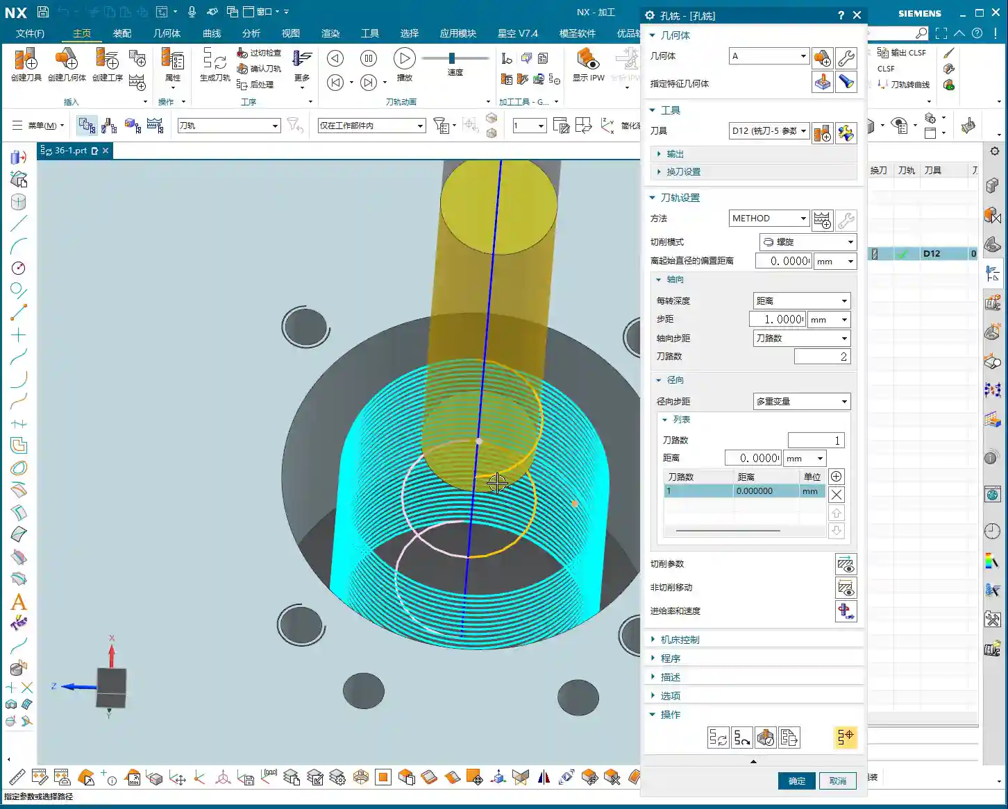
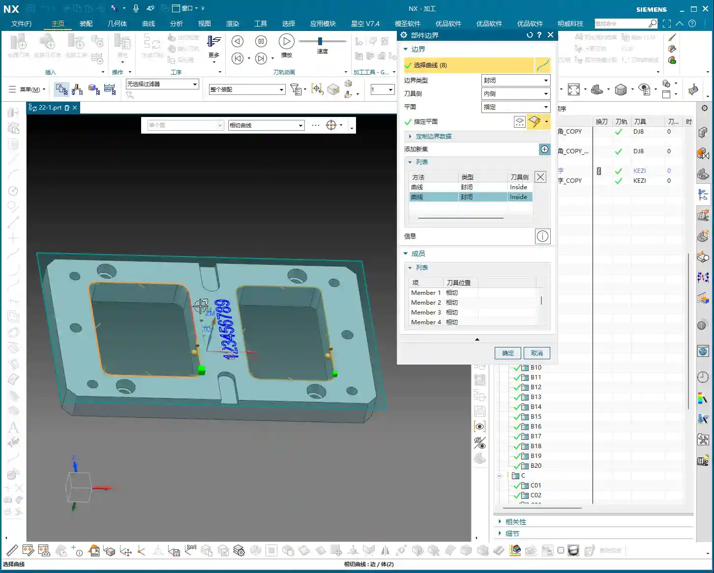
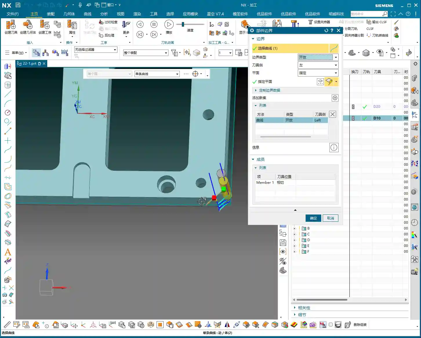
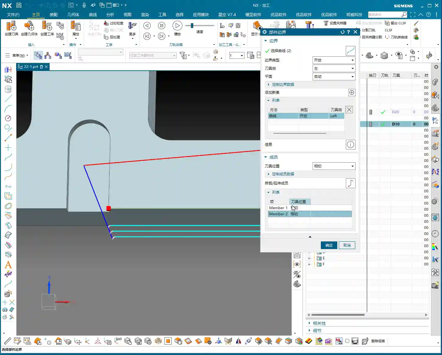
    Specify Top Surface: Determining Where Your Tool Engages the Work

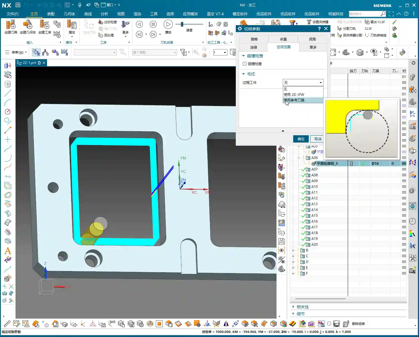
    What does “Specify Top Surface” mean? Simply put, it tells NX from which plane your drill will start drilling downwards. Don’t underestimate this small setting; it’s crucial for determining the starting point of your toolpath. Otherwise, for the selected hole feature, the software might default to starting the drill from its Z-axis position, which can easily lead to excessive Depth of Cut (DOC).

    Let me give you an example. For instance, if you have a part with a counterbore (or spot face), you first need to machine the counterbore, then spot drill and drill at its bottom. If you don’t “Specify Top Surface” and directly select that hole, NX might default to using the bottom surface of the counterbore as your starting Z-zero for the operation. This is where trouble starts: when your tool reaches the bottom of the counterbore, it might plunge directly at the programmed feed rate, instead of rapid positioning to the counterbore bottom first and then engaging with a normal feed rate. If this happens by accident, it can lead to chatter or, worse, tool breakage, and potentially damage the counterbore bottom surface.

    Therefore, when selecting a hole for a spot drilling operation, if there are other features above the hole, or if your machining start point is not the very top surface of the model, you absolutely must “Specify Top Surface.” Once you’ve accurately selected this face, the software will use it as your reference plane for tool entry. The tool will first rapid position above this plane, and then slowly feed downwards, which is much safer.

    In NX, “Specify Top Surface” has a “None” option. Selecting “None” means you’re leaving the decision entirely to the software; it will use the Z-coordinate of the geometric point you clicked as the machining zero point. In most cases, this is fine, but in complex scenarios like those I just described, or when you need to machine the lower section of a stepped hole, you absolutely must manually specify it – no cutting corners! This is the kind of practical knowledge you won’t find in textbooks.

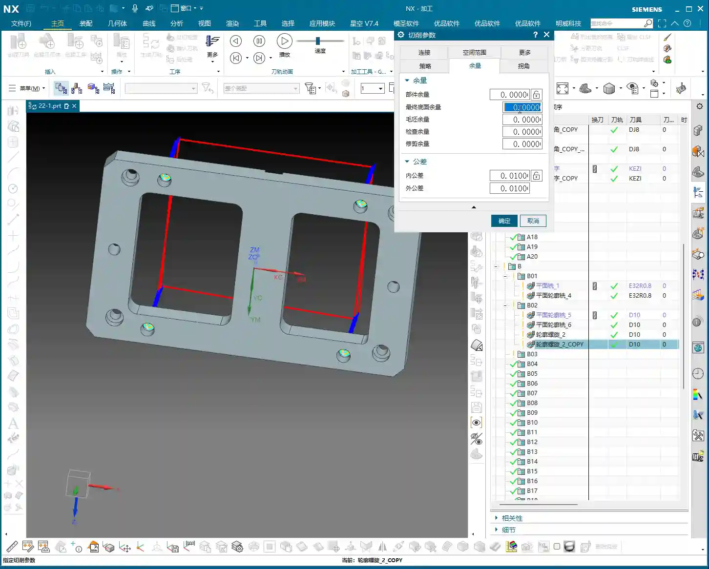
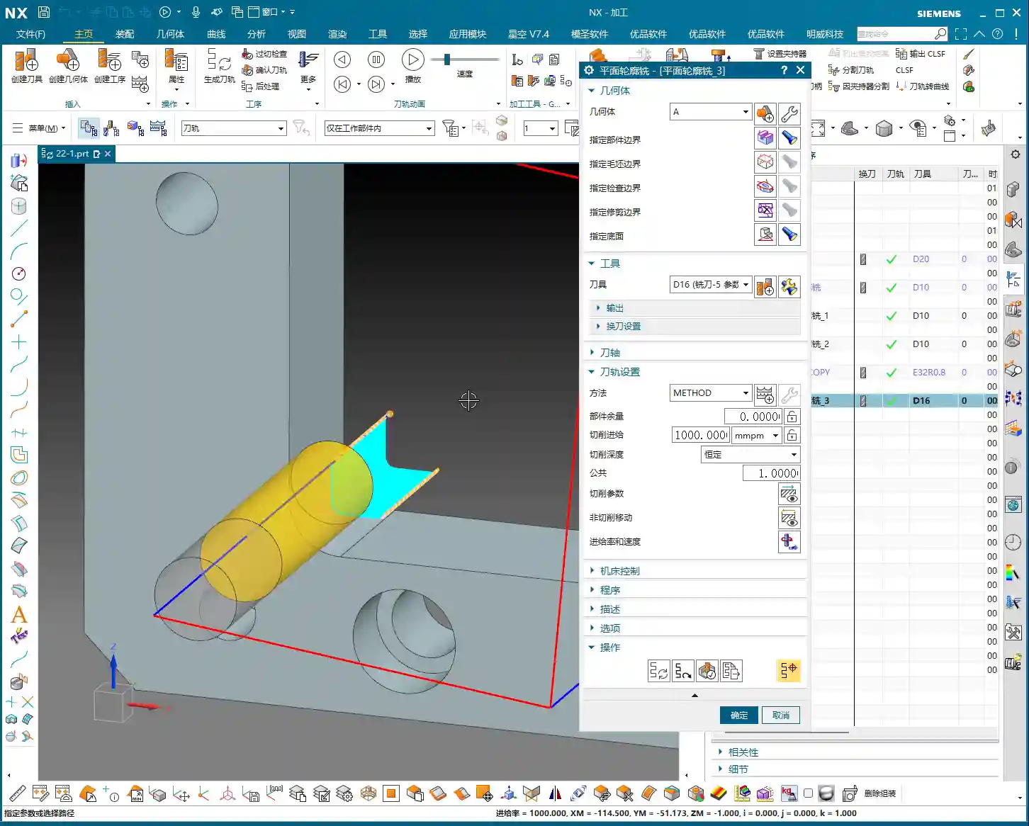
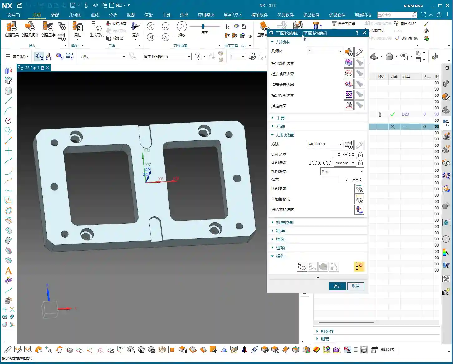
    Spot Drill Depth: Not Just Any Arbitrary Number Will Do

    Spot drill depth, as the name suggests, is how deep your drill will penetrate. Many new programmers think spot drilling is just making a mark, so they casually set the depth to 2mm. It’s not that simple! This depth isn’t a fixed rule; it depends on the situation.

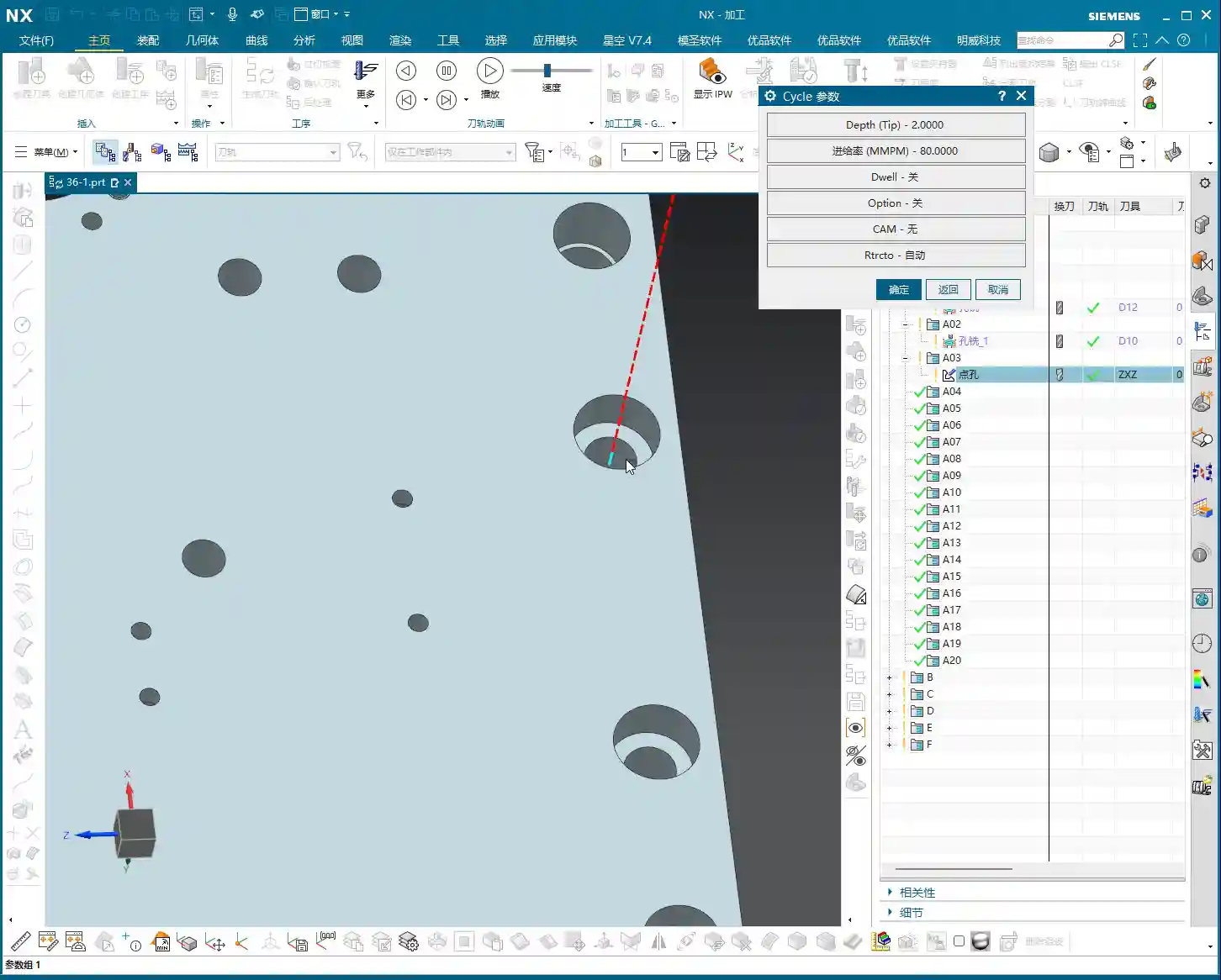
    In NX, there are generally two common types of depth settings for spot drilling: “Tip Depth” and “Model Depth”. For spot drilling, we typically use “Tip Depth”. This Tip Depth refers to the distance the drill tip penetrates downwards. For example, if you set a 10mm Tip Depth, the drill tip will go to the -10mm position from the specified top surface.

    So, you might ask, what’s the appropriate depth to set? This needs to be determined based on the actual situation. The purpose of spot drilling is usually to provide guidance for subsequent drilling, preventing the drill from drifting, and also to ensure sufficient bearing surface for countersunk screws or rivets. Generally, 1mm (approx. 0.04 inch), 2mm (approx. 0.08 inch), 3mm (approx. 0.12 inch), 4mm (approx. 0.16 inch) are common spot drill depth values.

    • If you just need to establish a pilot point for subsequent drilling, and the hole diameter isn’t large, a Tip Depth of 1-2mm (approx. 0.04-0.08 inch) should be sufficient.
    • If the hole diameter is larger, or if the subsequent hole requires high precision, you might need to use 3-4mm (approx. 0.12-0.16 inch) to provide a more stable guide for the drill.
    • Don’t just rely on software simulations; observe the cutting sparks! During actual machining, you need to observe chip formation and tool wear to determine if the depth is appropriate. If the depth is too shallow, the subsequent drill can wander; if it’s too deep, it’s just wasted effort and unnecessary.

    This depth also relates to the type of “cycle” you choose. For spot drilling, we generally use the G81 standard drilling cycle. If you need to drill deep holes later, that would be the G83 deep hole drilling cycle, where depth settings and retraction strategies become much more complex.

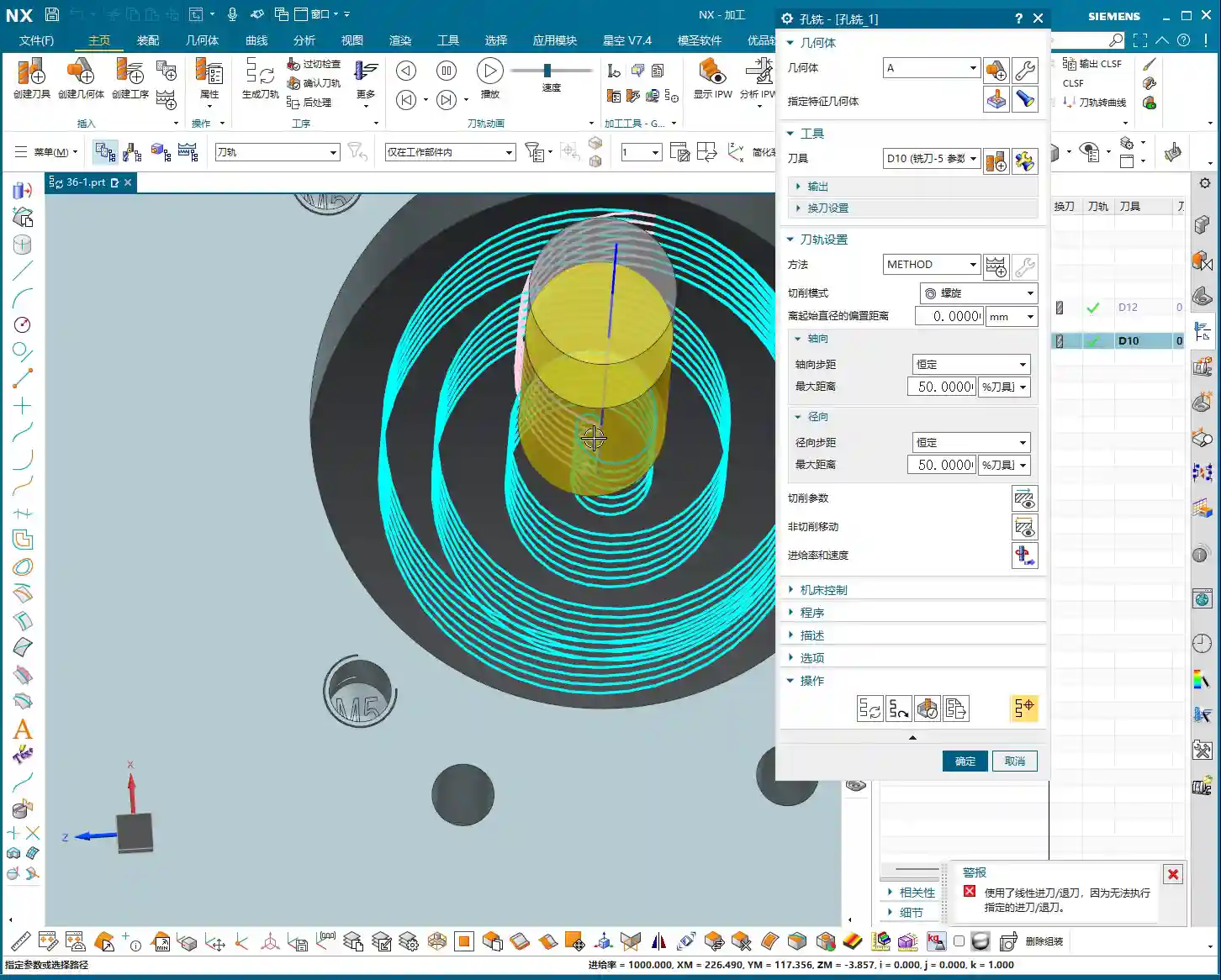
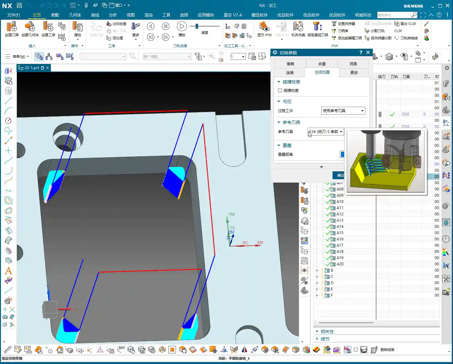
    Minimum Clearance Distance: The “Safety Line” for Tool Entry and Retraction

    In NX, there’s a parameter called “Minimum Clearance Distance,” and it’s also crucial. It refers to the distance the tool will rapid move (G00) from above the retract plane (or specified top surface) down to this safe clearance, and then from there, it will start cutting downwards at a normal feed rate (G01). For example, if you set it to 3mm (approx. 0.12 inch), the tool will first rapid down to 3mm above the top surface, and then slowly feed in.

    In G-code, this “Minimum Clearance Distance” typically corresponds to the R-value. For example, in G81 X… Y… Z-10.0 R3.0 F…, the R3.0 means the tool will rapid down to 3mm above the machining top surface, and then begin cutting at feed rate F. The significance of this parameter lies in improving both efficiency and safety.

    • If your workpiece surface is flat and the fixturing is stable, this clearance distance can be set smaller, for example, 1mm (approx. 0.04 inch), to reduce air cuts and improve efficiency.
    • However, if the workpiece surface is uneven, or if there’s raw casting or forged stock allowance, then this clearance distance should be appropriately increased, for example, to 3mm (approx. 0.12 inch) or even 5mm (approx. 0.20 inch), to prevent the tool from colliding with the workpiece during rapid moves and causing accidents.

    Setting these parameters isn’t about rote memorization; it requires comprehensive consideration of your actual workpiece, material, machine tool performance, and even tool condition. This is the kind of insight a master passes on to an apprentice, the “tricks you won’t learn from a textbook.”

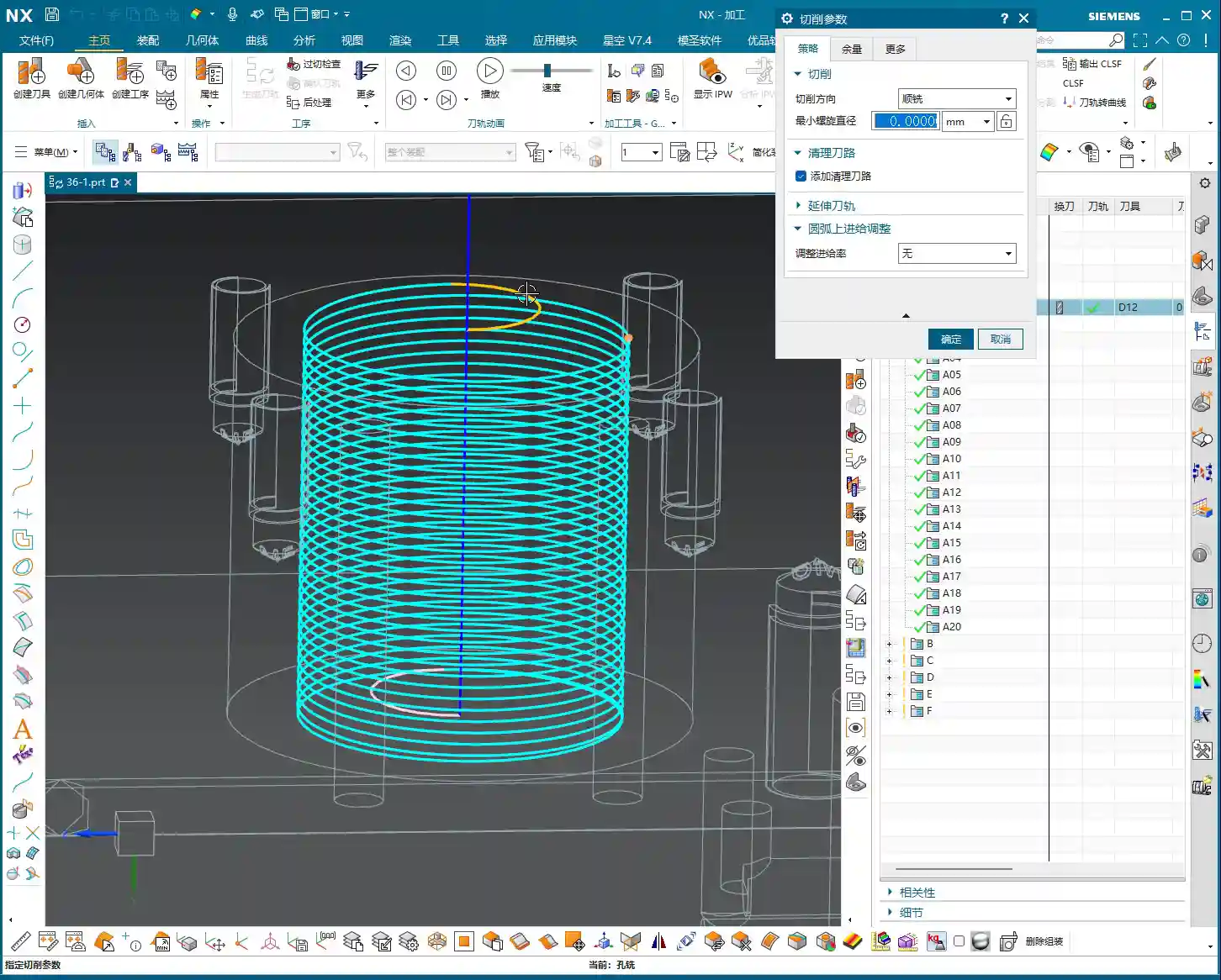
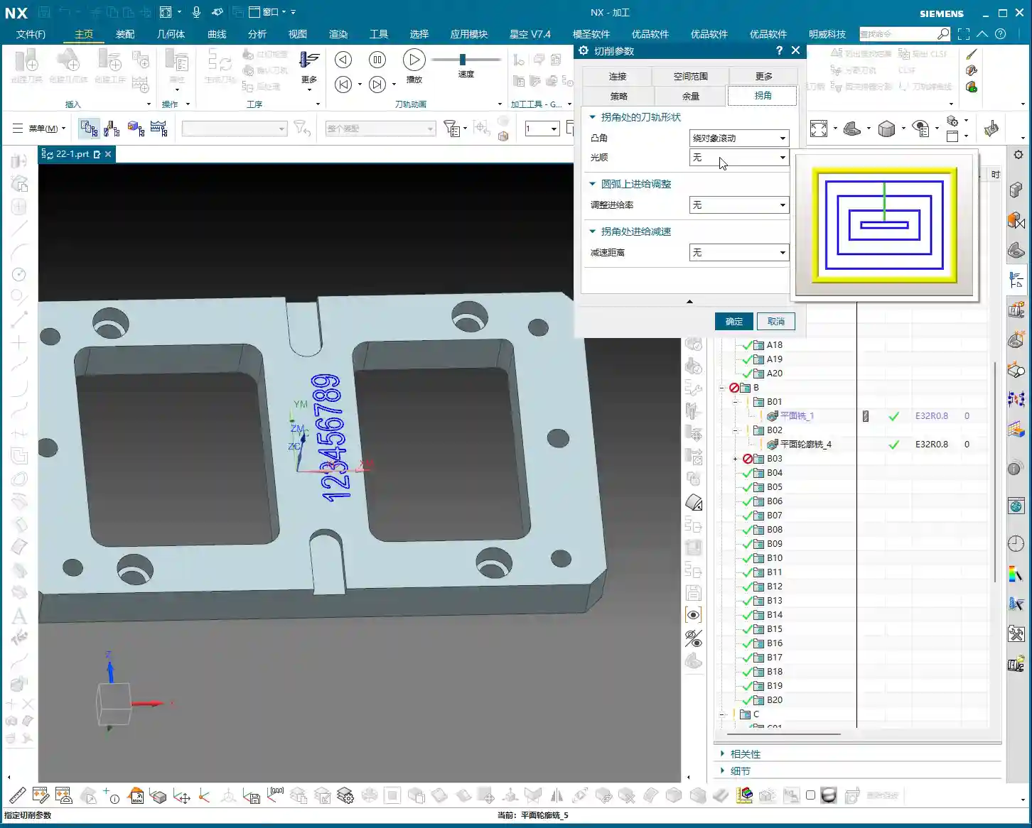
    The “Art of Compromise” in Drilling Cycles and Parameters

    NX offers many “cycle” options, such as “Standard Drill,” “Deep Hole Drill,” “Chip Break Drill,” etc. These correspond to different G-code commands; for instance, G81 is for standard drilling, and G83 is for deep hole drilling. For spot drilling, we generally use the simplest “Standard Drill.” Don’t be overwhelmed by the multitude of parameters; most of them you can leave at their default settings.

    The essence of spot drilling is tool entry, making a spot, and tool retraction. Therefore, besides “Specify Top Surface” and “Spot Drill Depth” which we’ve discussed, other parameters like “Feed Rate” and “Spindle Speed” must be determined based on the material. Aluminum can be cut faster, while tough materials like stainless steel and titanium alloys require a more cautious approach. Too fast, and you risk excessive tool wear; too slow, and it’s simply a waste of time and uneconomical.

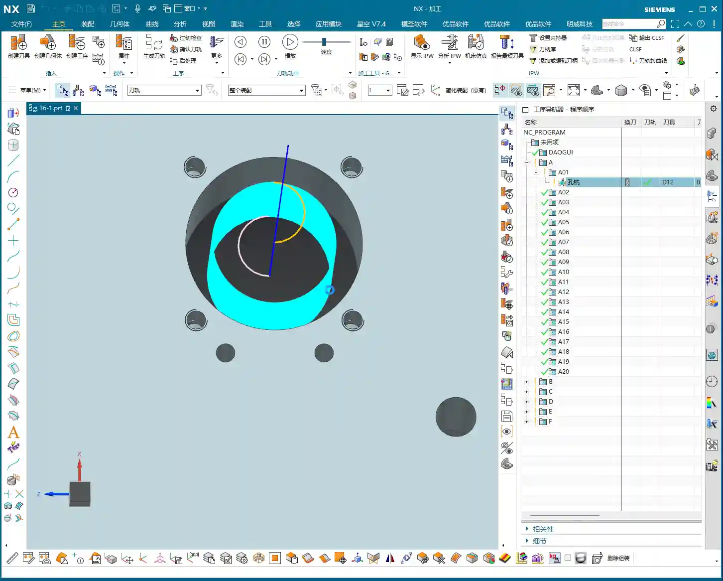
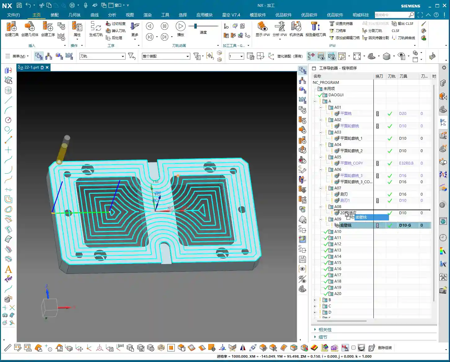
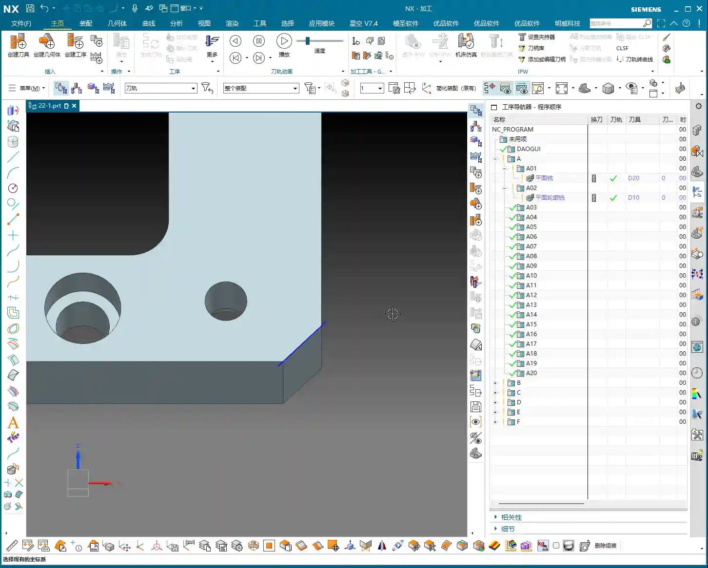
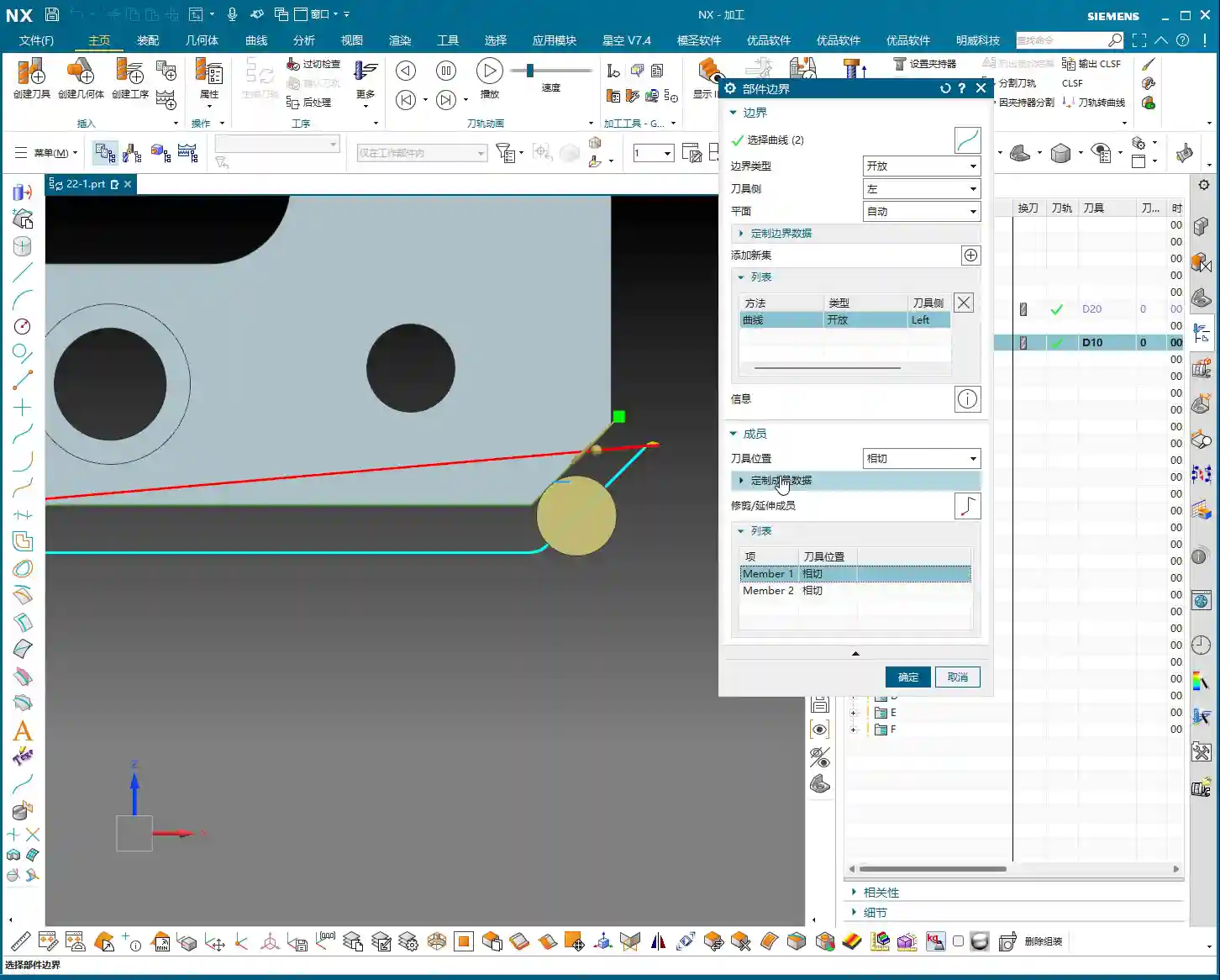
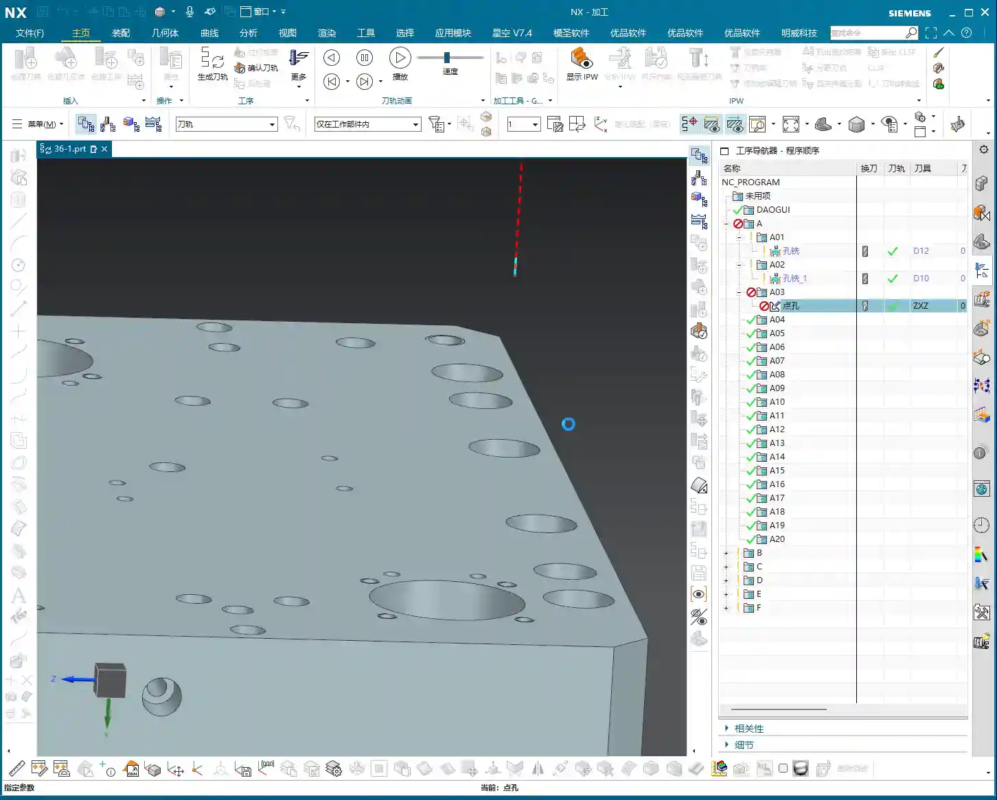
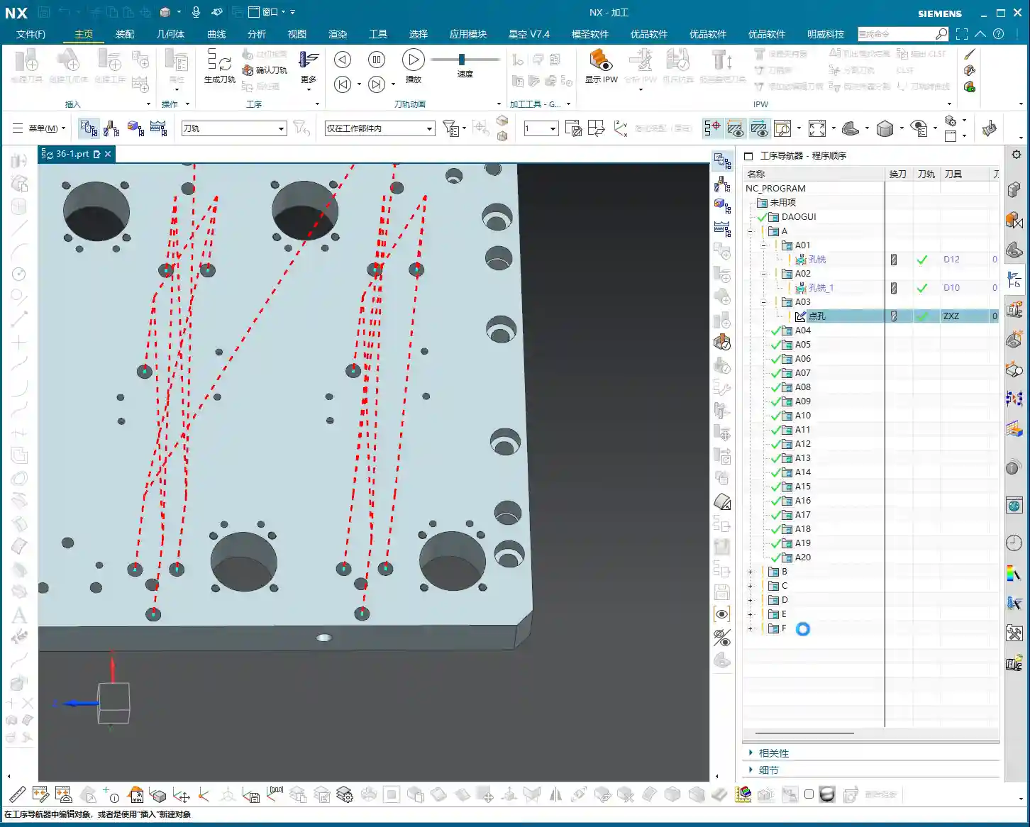
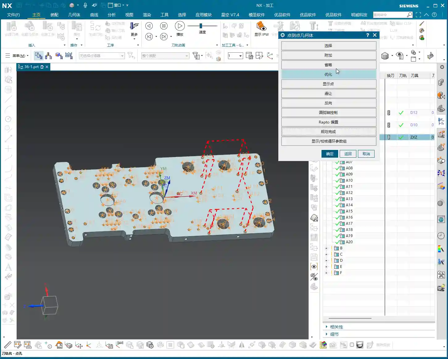
    Here’s a quick tip: when you select multiple holes for spot drilling, NX will, by default, machine all of them. However, sometimes we might not need to spot drill certain small holes or holes in specific locations. In such cases, within the graphical interface, you can roughly position your mouse over the holes you don’t need to machine and click once; they will be deselected. No need for pinpoint accuracy, a general location is fine. This allows for flexible control over which holes are spot drilled and which are not, avoiding unnecessary machining.

    Remember, the fundamentals remain constant. Spot drilling is a relatively simple operation, but you must thoroughly understand these three points: Top Surface, Depth, and Clearance Distance, to ensure your spot drilling is executed cleanly and provides a solid foundation for subsequent drilling.

    Summary: Pitfall Avoidance Guide

    • Don’t Blindly Trust Default Values: Especially for “Specify Top Surface,” in situations involving stepped holes or secondary operations, always specify it manually. Otherwise, the tool might start cutting from an unexpected position, leading to collisions or scrap parts.
    • Be Flexible with Depth: “Spot Drill Depth” is not fixed; set the “Tip Depth” according to hole diameter, material, and subsequent machining requirements. Generally, 1-4mm (approx. 0.04-0.16 inch) is the common range. Too deep wastes time, too shallow won’t provide adequate guidance.
    • Minimum Clearance Distance is Essential: The “Minimum Clearance Distance” relates to the efficiency and safety of tool entry and retraction. For raw stock or workpieces with uneven surfaces, appropriately increase the clearance distance (G-code R-value) to prevent tool collision during rapid traverse.
    • Cutting Parameters Must Be Rational: Spindle Speed (S) and Feed Rate (F) are determined by material characteristics, tool material, and diameter; they shouldn’t be too fast or too slow. This requires accumulated experience, so observe cutting sparks and chip formation.
    • Spot Drilling is Minor, But Details Determine Success: Mastering these practical tips will steadily improve your machining efficiency and product quality.

    👤 About the Author:
    The author is a veteran CNC machining professional with 15 years of industry experience, specializing in UG NX programming. This article is an original work representing personal practical insights.

    ⚠️ Copyright Notice: Unauthorized reproduction or distribution without prior communication is strictly prohibited.

  • Mastering NX Hole Milling Strategies and Top Offset: Master Wang’s 15 Years of Practical Experience

    📝 Key Takeaways: Master Wang provides an in-depth analysis of practical Siemens NX hole milling techniques, focusing on helical cutting modes, axial/radial distance settings, and the critical role of top/bottom offset. He emphasizes practicality, teaching how to optimize toolpaths by adjusting parameters, protect tools, enhance machining efficiency, and avoid tool breakage and scrap. This guide is ideal for frontline machining personnel.

    Hello everyone, I’m Master Wang. Today, let’s talk about hole milling in NX. Don’t underestimate a small hole; there’s a lot of expertise involved. A slight oversight can lead to a broken tool or even a scrapped workpiece. Listen up, I’m going to break down my 15 years of experience and explain it thoroughly to you.

    Hole Milling Strategies: Helical First

    We’ve pretty much covered the specialized hole features combined with the bottom surfaces we discussed previously. Select a hole, machine it, and you’re done. But have you noticed that it defaults to a single pass, spiraling down along the outer contour? If the hole is small, or if you’ve pre-drilled a pilot hole and left some stock, a single milling pass works fine.

    However, if you encounter a larger hole that cannot be covered in one pass, the default hole milling mode can be a bit awkward. In such cases, I often tell my apprentices: Don’t stubbornly stick to hole milling; if it’s not working, switch to Planar Milling! Treat the hole as a planar region and use the Roughing mode of Planar Milling; you can still achieve the desired result, and often with higher efficiency. Why? Because what is the Hole Milling command best at? It’s about spiraling from top to bottom in a single pass to clean out the hole. That’s its specialty!

    But then again, it’s Siemens NX; it has many functions. Hole milling can actually achieve similar results to planar milling, but it depends on how you adjust the parameters. Let’s start with the most commonly used “Helical” mode.

    Detailed Explanation of Helical Cutting Mode

    This “Helical” mode is my preferred choice and one I often select in my NX templates. It’s efficient and provides stable cutting. It’s the default, so you can generally use it directly without overthinking. We’ll mainly look at the following parameters:

    Axial Distance (Step-down)

    This Axial Distance, simply put, is how much Depth of Cut (DOC) you take downwards with each helical turn. For example, if I set it to 0.3 mm, the toolpath will be dense, and the cutting force will be uniform. If you set it to 1 mm, the toolpath becomes sparse, and the Depth of Cut (DOC) suddenly increases. Especially with hard materials, uneven tool loading can easily lead to chipped edges or even direct tool breakage! Therefore, this parameter must be determined based on your tool material, workpiece material, and machine rigidity. Don’t just rely on software simulations; observe the actual cutting sparks and sounds!

    Number of Radial Passes (Helical Turns)

    Next is the Number of Passes. For this parameter, I advise you not to mess with it normally! Set it to 1. If you set it to 2, 10, etc., it will divide the milling into several layers. After milling one layer, it will retract the tool, then mill the next layer. This results in too many air cutting moves, significantly reducing efficiency, and the impacts from retracting and re-engaging the tool also increase tool wear. What are we aiming for? One continuous pass, clean and decisive!

    Radial Distance (Toolpath Offset)

    This Radial Distance parameter is quite interesting. The default is 0, meaning it completes one turn. If you set a value, say 10 mm, it will add another pass or several passes on the outer circumference, effectively milling the hole larger. This is precisely to address the issue mentioned earlier, where a tool cannot mill a large hole in a single pass. It will first helical mill the interior, then retract the tool, and then helical mill another circle, offset by 10 mm from the outside. Although this method involves one more tool retraction than a single continuous pass, for large holes that cannot be covered in one go, it’s more flexible than simple planar milling, especially when high verticality of the hole wall is required.

    Remember, these parameters are not rigid; they depend on the size of your chosen tool, the hole diameter, and your cutting strategy. If your set radial distance is greater than the stock remaining for the hole, there will be no room for additional passes, and the software will optimize it out.

    Key Parameters: Top and Bottom Offset

    Next, let’s discuss two very practical parameters that many newcomers overlook but are crucial for protecting tools and ensuring machining quality: Top Offset and Bottom Offset.

    Top Offset: The Tool’s “Soft Landing”

    I’m telling you, this Top Offset is extremely important! It means that the tool will perform an additional air cut for a certain distance above the actual machining top surface before formally starting to cut. For example, if you set it to 10 mm, the tool will start its helical motion 10 mm above the hole’s top surface and then gradually cut downwards. Why do we do this?

    1. Tool Protection: Especially when milling hard materials, if you let the tool “plunge” directly into the workpiece surface to start cutting, the impact force is very high, and the tool tip can easily chip. With Top Offset, the tool makes a “soft landing,” with cutting forces gradually increasing, significantly extending tool life.
    2. Avoid Surface Scratches: Some workpieces require high surface finish, and direct entry can leave scratches on the surface. An initial air cut allows the tool to enter a stable cutting state.
    3. Managing Stock: If your workpiece has remaining stock on the top surface, such as a cast blank, you can adjust this parameter to have the tool start cutting from above the stock.

    Don’t cut corners here, especially during Roughing. Setting a 5-10 mm offset here offers significant benefits.

    Bottom Offset: The “Refined Finish”

    If there’s a Top Offset, there’s naturally a Bottom Offset. This is also easy to understand: it means the tool will mill a little extra at the bottom of the hole. For example, if you set it to 5 mm, it will mill 5 mm deeper than the defined hole bottom. This parameter is mainly used to:

    1. Thoroughly Clear the Bottom: Ensure that burrs and residual stock at the bottom of the hole are cleaned, especially for blind holes or holes with chamfered or filleted bottoms.
    2. Avoid Tool Marks: Sometimes, when the tool cuts to the bottom, minor tool marks may appear due to changes in cutting force. Milling a little extra ensures a flat and smooth bottom.
    3. Address Positioning Errors: If there are minor positioning errors in your workpiece or Z-axis errors in the machine, extending downwards a bit can compensate for these errors, ensuring the actual machining depth meets specifications.

    You can even input a negative value, but that would mean not milling to the design depth, which is generally not recommended. Typically, a 0.5 to 2 mm bottom offset is sufficient.

    Stock and Non-Cutting Moves

    As for Side Allowance (side stock), that’s straightforward: the amount left for the Finishing pass. We control the top stock through Top Offset. These are standard operations and don’t require much elaboration.

    In Non-Cutting Moves, the main focus is on the entry and exit methods. The default Helical Ramp or Arc Lead-in are generally the most suitable, allowing for smooth entry and exit into and out of the cut. This prevents sudden tool impact and reduces Chatter. Unless there are special circumstances, such as an obstruction near the hole, you typically won’t need to consider changing to a Linear Lead-in or similar. If the program is set up correctly, these parameters usually don’t need modification.

    Other Hole Milling Modes and Entry Strategies

    NX has several other hole milling modes, such as helical out-cut, constant helical, and so on. These modes are actually similar to the Roughing strategies in Planar Milling, all designed to progressively enlarge the hole. In actual work, we use them less frequently, primarily relying on the combination of helical entry with Radial Distance.

    Comparison of Various Entry Methods

    Take tool entry, for example. “Linear Lead-in” means plunging straight in, which creates a high impact on the tool. Unless it’s a particularly soft material or the tool is a drill-mill, it’s not recommended. In contrast, “Helical Ramp” and “Arc Lead-in” allow the tool to maintain stability during cutting, reducing impact. Therefore, under normal circumstances, I always have my apprentices choose helical or arc entry; it’s a fundamental skill for tool protection.

    Helical Out-Cut Mode

    There’s also a “Helical Out-cut” mode, which processes the hole spiraling outwards from the center, similar to “inside-out” Roughing in Planar Milling. This mode can also be quite useful in certain situations, especially when the hole diameter is large, and the tool cannot machine the entire hole in one pass. Its advantage is a relatively uniform cutting load, but its drawback is a longer toolpath and potentially more air cutting moves.

    Summary: Pitfall Guide

    1. Mode Selection: For small holes or pre-drilled holes, use the “Helical” mode for a single, continuous pass. For large holes or those that cannot be milled in one pass, prioritize “Planar Milling” for Roughing, or use the “Helical” mode in Hole Milling combined with “Radial Distance.”
    2. Axial Distance (DOC): Set strictly according to material hardness, tool diameter, and machine rigidity; err on the side of smaller values to prevent tool chipping.
    3. Number of Passes: Keep at 1, aiming for a single, continuous pass to improve efficiency.
    4. Top Offset: Essential for Roughing, providing the tool with a “soft landing” and extending tool life. The value is usually set to 5-10 mm.
    5. Bottom Offset: Ensures a clean hole bottom and compensates for minor errors. The value is usually set to 0.5-2 mm.
    6. Entry Method: Prioritize “Helical Ramp” or “Arc Lead-in” for smooth tool entry, avoiding impact.
    7. Parameter Flexibility: Memorizing parameters is useless; the core is to understand the machining logic behind each parameter and its impact on actual cutting, then adjust flexibly according to practical conditions.

    Alright, that’s all for today. In NX Programming, practical experience is key! Watch more, learn more, and get hands-on experience, and you too can become a master!

    👤 About the Author:
    The author is a veteran CNC machining professional with 15 years of industry experience, specializing in UG NX programming. This article is an original work representing personal practical insights.

    ⚠️ Copyright Notice: Unauthorized reproduction or distribution without prior communication is strictly prohibited.

  • Practical Analysis of Planar Milling in NX: Master Wang’s Step-by-Step Guide to Efficient **Roughing

    📝 Key Takeaways:

    Practical Planar Milling in NX

    Introduction…

    Introduction: Master Wang Reviews Planar Milling Fundamentals

    Hello everyone, I’m Master Wang! Last time, we thoroughly explained the intricacies of planar milling, covering both GSM and legacy planar milling operations. Today, let’s dive into a practical exercise. We’ll take this part on hand and program it from start to finish. Listen up, follow my thought process, and see how this job is done. I’ll share all the practical tricks you won’t find in textbooks, explaining them all to you today!

    Part Analysis and Tool Selection Strategy

    Part Feature Interpretation: Dimensions and Challenges

    First, let’s analyze this part’s characteristics. Looking at its edges, some areas have small R6 fillets. This means you can’t use a tool with a diameter greater than 12mm (approx. 0.47 inch) to cut them aggressively, or you definitely won’t achieve a clean finish, and might even cause a tool crash. Most other corners are larger and relatively easier to handle. As for the holes, we’ll be machining the two larger ones on top, and the central 14mm (approx. 0.55 inch) diameter hole. We can set aside the other smaller holes for now; they are not the main focus for planar milling.

    Roughing Tool Selection and Overall Approach

    Since efficiency is key, the first step is always **roughing**. My approach is to first remove most of the material with a larger tool, then use a smaller tool for detail **finishing passes** in the corners. Here, we can directly select a D32 R0.8 (approx. D1.26 inch, R0.031 inch) corn cutter. Why this one? Because it’s large enough, offers high cutting efficiency, and can quickly rough out the part’s general contour. Don’t worry about those small R6 fillets for now; we’ll address them later during **corner cleanup**.

    Practical NX Operations: Stock Definition and Roughing

    Stock Definition and **Work Coordinate System (WCS)** Setup

    Alright, listen up! In Siemens NX, the first thing we need to do is define the stock. The simplest method is to use a Bounding Block. First, select the part, then generate it with a single click, essentially creating an ‘outer shell’ for it. Next is the crucial WCS (Work Coordinate System). I typically set it on the bottom face of the part, which makes subsequent depth control more intuitive and accurate. Remember, the position and orientation of the coordinate system must match your machine’s **clamping** or **fixturing** method. This is the fundamental basis for avoiding errors!

    Operation Creation: Planar Milling Roughing

    Next, let’s create the operation. Select the Face Milling operation.
    Tool: The previously selected D32 R0.8 (approx. D1.26 inch, R0.031 inch).
    Machining Area: Select the entire bottom face of the part; we’ll mill it flat first.
    Now for the critical part: **Allowance Settings** (or “Stock to Leave”)! To ensure enough material for subsequent **finishing passes**, I’ll leave 0.1mm (approx. 0.004 inch) on the bottom face and 0.2mm (approx. 0.008 inch) on the side walls. These values are empirical; they can be adjusted based on material and accuracy requirements. Don’t underestimate this small amount of stock—it directly impacts tool life and surface finish during **finishing passes**. Finally, generate the tool path. First, review the results to ensure the tool path covers the entire machining area with no missed regions. This **roughing** program is essentially complete.

    Open Boundary and Internal Hole/Slot Machining Strategies

    Boundary Roughing: Planar Profile Milling

    Once the bottom face is roughed, next we’ll address the external contours. Here, we’ll use Planar Profile Milling. We’ll continue to use the same D32 R0.8 (approx. D1.26 inch, R0.031 inch) tool. For the geometry, select the part’s outer contour, which is an open area. Here’s the key: **Approach Method** (or “Entry Method”)! Many beginners prefer arc entry, thinking it looks cleaner, but in **roughing** scenarios like this, arc entry can leave marks at the starting point and even lead to excessive localized **depth of cut (DOC)**. I recommend switching directly to linear entry, with a percentage of 60%, no extension, and a height of 0. This creates a more stable entry path and avoids unnecessary interference. Regarding cutting parameters, the stepover can be adjusted to around 50%, allowing it to cut back and forth, efficiently clearing the peripheral material. Don’t just rely on software simulation; observe the cutting sparks and chip formation—that’s the true feedback of what’s happening!

    Internal Hole/Slot **Corner Cleanup** and Helical Milling

    With the external contour handled, now it’s time for the internal holes and corners. First, for the internal **corner cleanup**. During previous **roughing**, the D32 (approx. D1.26 inch) tool would certainly leave many corners untouched. Now we’ll use a D10 (approx. D0.39 inch) tool. Don’t ask why not a D16; my experience tells me that if you want to cleanly machine an R6 fillet, going straight to a smaller tool like a D10 is more efficient, saving you a tool change. Use Planar Profile Milling for **corner cleanup** in these internal enclosed areas. Select the corresponding boundaries, again leaving 0.2mm (approx. 0.008 inch) for side walls and 0.1mm (approx. 0.004 inch) for the bottom face.
    Next, for those larger holes, such as the 14mm (approx. 0.55 inch) diameter one. For holes like these, Helical Milling (Contour Profile – Helical) is most suitable. Using the same D10 tool, select the inner wall of the hole as the machining boundary. Allow the tool to feed in a helical manner; this results in more stable cutting and a better surface finish on the hole wall, avoiding the impact of a direct plunge. The default helical entry method here is perfectly fine.

    Master Wang’s Mini-Lesson: Tool Path Optimization and Practical Experience

    Listen up, programming isn’t just about generating tool paths; more importantly, it’s about optimization.
    Cutting Efficiency: As with the previous **roughing** operation, we used a large tool like the D32 (approx. D1.26 inch) to remove as much material as possible. **Stepover** and **depth of cut (DOC)** must be determined in conjunction with machine rigidity and material hardness. Don’t blindly aim for large values; if the tool starts to **chatter** or experience **tool deflection** as soon as it engages, that’s definitely not acceptable.
    Tool Life: The entry/exit methods and the setting of cutting parameters all influence tool life. For instance, changing from arc entry to linear entry earlier was specifically to prevent premature localized tool wear.
    Tolerance Control: Before the final **finishing pass**, ensure that the roughing stock allowance is uniform. If the roughing allowance is uneven, the tool will experience unbalanced cutting forces during **finishing**, making tolerance control difficult. For tolerances like ±0.005mm (approx. ±0.0002 inch), you must learn to use **machine compensation** or fine-tune feed rates and spindle speeds to control cutting forces and minimize deformation.
    Don’t just rely on software simulation; observe the cutting sparks and listen to the machine’s sound. The spark color and chip shape—these are all experience-based insights you won’t learn from textbooks!

    Summary: Pitfall Avoidance Guide

    Finally, Master Wang will give you some more practical tips. These are all pitfalls I’ve encountered, so you can avoid making the same mistakes.
    1. Tool Selection: From large to small, from rough to finish. This is a fundamental principle; don’t try to achieve everything in one step, especially with complex parts.
    2. Stock Definition: Must be accurate. If the stock definition is inaccurate, the tool path can easily lead to air cuts or tool crashes.
    3. Coordinate System Setup: Must align with fixturing. This is fundamental—a weak foundation will crumble.
    4. Approach/Retract Strategy: Smooth transitions. Especially during **roughing**, avoid sudden engagements or exits, which can cause excessive **depth of cut (DOC)** and affect both surface finish and tool integrity.
    5. Allowance Control: Leave sufficient material for finishing. Too little roughing allowance makes it difficult to achieve precision in **finishing**; too much burdens the **finishing pass**.
    6. Practical Observation: Be highly observant of your surroundings. The sound of the machine, the flow of coolant, the color of sparks, the shape of chips—these are all direct feedback on whether your programming parameters are reasonable. Don’t just stare at the screen watching NX simulations; that’s just theory. Actual machining is the only true test.
    7. Material Properties: Don’t forget to consider them. Cutting parameters and tool wear differ significantly for various materials, so keep this in mind when programming. For example, would you dare machine titanium alloys or superalloys the same way you mill aluminum? That’s just burning up your tools!

    👤 About the Author:
    The author is a veteran CNC machining professional with 15 years of industry experience, specializing in UG NX programming. This article is an original work representing personal practical insights.

    ⚠️ Copyright Notice: Unauthorized reproduction or distribution without prior communication is strictly prohibited.

  • Siemens NX 2D Dynamic Milling Practical Masterclass: Eliminate Inefficient Retractions, Master Wang

    📝 Key Takeaways: Master Wang shares core Siemens NX 2D Dynamic Milling techniques. Learn how to boost Roughing efficiency with “Adaptive Milling” and overcome 3D simulation challenges for 2D programs using “Floor Wall Milling”. In-depth analysis of Stepover, Layers, and critical Retraction parameters to optimize your toolpaths, reduce costs, eliminate inefficiency, and become a machining expert.

    Master Wang’s Insight: The Practical Essence of 2D Dynamic Milling

    Hello everyone, I’m Master Wang. Today, no fluff, just practical insights! Many ask me, ‘Master Wang, what’s the real difference between ‘Planar Milling’ and ‘2D Dynamic Milling’ in NX, and how can we use them efficiently?’ Listen up! Today, I’m going to break it down for you, revealing practical tips you won’t find in textbooks!

    There’s a command in NX called “Solid Profile 3D”—we’ll set that aside for now, it’s a bit complex. Today, let’s dive straight into 2D Dynamic Milling, also known as 2D Adaptive Milling in NX. Different names, but the principle and objective are the same: during Roughing, it aims to create smoother toolpaths, minimize sudden changes in cutting force, and improve both efficiency and tool life.

    Key Change: From “Follow Periphery” to “Adaptive Milling”

    Previously, with Planar Milling, toolpaths were typically parallel, and the cutting pattern was often “Follow Periphery”. When encountering corners, the tool would suddenly engage with a full Depth of Cut, leading to chipping. 2D Dynamic Milling is different; its biggest and most crucial change lies in its cutting pattern.

    Select 2D Dynamic Milling (or 2D Adaptive Milling), and you’ll find its interface is almost identical to Planar Milling. That’s right, it evolved from Planar Milling. But, if you click in and change the cutting pattern from “Follow Periphery” to “Adaptive Milling”, this feature completely transforms!

    Changing just this one parameter alters the tool’s cutting method. It strives to maintain a constant cutting width, using small Stepover and high feed rates to create a “peeling” type of toolpath. This effectively prevents the tool from engaging with a full Depth of Cut, making it particularly suitable for deep pocket Roughing and hard material machining.

    Toolpath Boundaries and Floor Definition

    Defining the toolpath range is similar to Planar Milling.

    • Part Boundaries: Specify the boundary curves of the area you want to machine. Make sure to select them precisely; don’t over-mill or under-mill.
    • Floor: Select the bottom face for machining. This face defines your machining depth. Beginners often make mistakes here; selecting the wrong one can lead to over-machining (milling through) or not reaching the desired depth. Remember, choose the face you ultimately intend to machine to.

    For the tool, just pick a common one for now, like a D10 end mill (10mm diameter). Generate the program first, and then we’ll fine-tune it step-by-step.

    Simulation: Avoiding the “No Stock” Pitfall

    Alright, the program is generated. Let’s run a simulation to check the results. Click “Tool Path Verification” and then select 3D Simulation. You might find it throws an error! It’ll say “No Stock” or fail to simulate. This is a common pitfall for many beginners, and textbooks often don’t tell you about it.

    NX 2D Program Simulation Pain Point: Doesn’t Recognize Solids, Only Wires

    Why the error? Because 2D programs, like Planar Milling, only recognize wires, not solids. They don’t know what your stock looks like, so they can’t perform a 3D solid cutting simulation. If you click ‘Simulate’ directly at this point, the system gets “confused”.

    Master Wang’s Secret: Add a “Floor Wall Milling” Operation as Stock

    The secret to solving this is simple: before your 2D Dynamic Milling program, add a “Floor Wall Milling” operation to serve as your stock reference!

    1. Create a new “Floor Wall Milling” operation, define the part and floor arbitrarily, and select any tool.
    2. Generate this “Floor Wall Milling” program.
    3. Drag your 2D Dynamic Milling program underneath this “Floor Wall Milling” program.

    Now, select your 2D Dynamic Milling program again and run a 3D simulation. You’ll see a miracle happen! The simulation works normally! This is because 2D Dynamic Milling “inherits” the stock state after the “Floor Wall Milling” operation, so it now knows where to start cutting. This little trick will save you a lot of debugging time!

    Through simulation, you’ll observe the tool descending in a helical motion, then expanding outwards within the cavity like a snail shell, with a very stable cutting process. That’s the beauty of dynamic milling! It equalizes the tool’s cutting load, which allows for higher cutting parameters and boosts machining efficiency.

    Core Parameter Analysis: Stepover, Layers, and Retraction Control

    NX has parameters galore, but only a few core ones truly impact machining quality and efficiency. Today, we’ll focus on dynamic milling’s key parameters.

    1. Stepover: Cutting Width and Efficiency

    Stepover is the distance the tool moves sideways with each pass.

    • Percentage: The default is usually around 10% of the tool diameter. For example, for a D10 tool (10mm diameter), 10% is 1mm. This value determines your cutting width and toolpath density. A small Stepover results in dense toolpaths and a better surface finish but takes longer; a large Stepover increases efficiency but might leave uneven stock after Roughing.
    • Constant: You can also set it to a fixed value, such as 0.5mm. Whether to use a percentage or a fixed value depends on your tool and material. For Roughing, generally choose a larger Stepover to improve efficiency, but don’t exceed 30-40% of the tool’s effective cutting edge width, or it could lead to Chatter or tool breakage.

    2. Layers: Roughing Depth Strategy

    Layers, also referred to as Depth per Cut, controls the tool’s multi-level cutting in the Z-axis direction.

    • If you set a specific value, such as “20”, it will divide the total machining depth into 20 layers for processing.
    • However, in Roughing, for maximum efficiency, we usually set this value to 0. Setting it to 0 means one continuous cut to depth (or “finish to floor”). The tool will helix down from the top and then machine directly to the defined floor depth, reducing retractions and layering. This is crucial for boosting efficiency in dynamic milling!

    3. Minimum Corner Radius: Corner Smoothness

    This parameter is found on the “Strategy” page. It defines the minimum corner radius the tool can follow when turning.

    • The default is typically 5% of the tool diameter. For a D10 tool (10mm diameter), this means a 0.5mm corner radius.
    • A larger value results in smoother corners and less force on the tool; a smaller value creates sharper corners, but the tool might experience higher forces in those areas. Typically, keeping the default is fine; consider adjusting only for specific Corner Cleanup requirements.

    4. Retraction Control (Height & XY Transfer): Efficiency Killer or Safety Net?

    Tool retraction is a critical aspect of machining, directly impacting idle travel time and overall efficiency.

    • Height: This controls the tool’s retraction height when moving from one cutting area to another within the same layer. The default is 1mm, meaning it retracts 1 millimeter each time. Setting this value too high increases idle travel time; setting it too low risks collision with the workpiece, which is unsafe. The default 1mm is generally sufficient.
    • XY Transfer / Global Retraction: This parameter typically appears as a very large percentage, such as 5500%. It controls the retraction strategy between different cutting regions or between different layers.
      • Larger Value: The tool is more inclined to avoid retracting, opting for “smooth connection” paths, moving quickly across the workpiece surface as much as possible, reducing the number of retractions. This is KEY to boosting efficiency! I usually set it to a very high value, like 10000, or even higher, to ensure more continuous tool motion.
      • Smaller Value: The tool will retract very frequently, even for short movements. This causes idle travel time to increase exponentially, resulting in extremely low efficiency and machining times that will drive you crazy!

      Therefore, for this parameter, NEVER set it too low! Try to give it a large value, allowing the tool to move quickly and continuously in the XY plane, which will significantly improve your machining efficiency.

    Side Wall Corner Cleanup: Another Advantage of Dynamic Milling

    Dynamic milling not only efficiently performs Roughing on planar surfaces but also offers unique advantages in side wall Corner Cleanup. Due to its “adaptive milling” characteristics, the cutting load on the tool in corners is well-controlled, minimizing the risk of chatter marks and ensuring uniform stock for subsequent Finishing passes.

    If you notice during simulation that the side walls don’t show a “highlighted” sheen, it indicates that there is still stock remaining on the side walls. This is normal; Roughing aims to quickly remove most of the material, preparing for the Finishing pass. We’ll cover Finishing toolpaths in detail next time.

    Summary: Pitfall Avoidance Guide

    • Essential Parameter Change: The core of 2D Dynamic Milling is to change the cutting pattern to “Adaptive Milling”.
    • Simulation Trick: Before running a 3D simulation for a 2D program, always add a “Floor Wall Milling” operation beforehand as a stock reference; otherwise, it will error out.
    • Efficiency Boost: During Roughing, set Layers to 0 (one continuous cut to depth), and adjust the Stepover appropriately based on the material and tool.
    • Reduce Retractions: Maximize the percentage value for “XY Transfer” (or “Global Retraction”), for example, 10000, to ensure more continuous tool motion and reduce idle travel time.
    • Stock Check: After simulation, observe if the part surface has a “highlighted” sheen. Areas without sheen indicate remaining stock, requiring a subsequent Finishing pass.

    These are experiences I, Master Wang, have accumulated over more than a decade in the trenches. I hope they are helpful to you, the next generation! Practice makes perfect; get your hands dirty, observe closely, and you’ll become a true machining expert!

    👤 About the Author:
    The author is a veteran CNC machining professional with 15 years of industry experience, specializing in UG NX programming. This article is an original work representing personal practical insights.

    ⚠️ Copyright Notice: Unauthorized reproduction or distribution without prior communication is strictly prohibited.

  • NX Planar Profile Milling Corner Cleanup and Reference Tooling in Practice: Master Wang Teaches You

    📝 Key Takeaways: ** Today, Master Wang will personally guide you through the ultimate technique for NX Planar Profile Milling Corner Cleanup. The core lies in applying the “Reference Tool” feature. By accurately setting the roughing tool information, the Corner Cleanup tool can intelligently identify and remove residual material, preventing tool crashes. Concurrently, Master Wang shares practical experience on selecting end mills (E-type tools) and setting the overlap distance, ensuring both machining quality and efficiency. **

    Introduction: The Importance of Corner Cleanup – Small Details, Big Impact

    Listen up, folks! Last time, we covered roughing side wall treatment and tool compensation – these are fundamental skills. But today we’re tackling a tough nut to crack – Planar Profile Milling Corner Cleanup. Don’t think Corner Cleanup is just about switching to a smaller tool and milling away. There’s a lot more to it. Mess it up, and you’re either leaving residual material or causing tool crashes – all wasted effort. In our line of work, you need to be observant and know your stuff. These practical tips, which you won’t find in textbooks, Master Wang will break down and explain thoroughly today!

    Residual Material from Roughing: Why Corner Cleanup is Necessary?

    The ‘Side Effects’ of Large Tool Roughing

    In machining, to improve efficiency, we typically use larger tools for roughing. For example, you might use a D32 flat end mill for roughing a part’s side walls. This D32 tool can quickly mill away most of the material, no problem. However, issues arise when the part’s internal corner radius is smaller than the roughing tool’s radius.

    For instance, if your part has an R10 internal corner radius. A D32 tool has a radius of R16. Obviously, an R16 tool cannot perfectly enter an R10 corner. It can only follow an R16 path, which means it will inevitably leave a ring of residual material at the R10 corner. If this residual material isn’t cleaned up, subsequent finishing passes will be problematic. The finishing tool will first encounter these roughing remnants, which could, at best, affect dimensional accuracy and surface quality, or at worst, cause immediate tool breakage!

    Residual Material Traps Invisible to the Naked Eye

    Don’t just rely on software simulations. When the tool runs on the machine, the cutting sparks and sounds are the most accurate feedback. Sometimes, the screen looks perfectly clean, but in reality, a thin layer of residual material remains. You might not even spot this with your eyes, but it’s physically there, waiting to cause problems for your subsequent finishing passes. Therefore, this Corner Cleanup step must not be overlooked!

    The Core of NX Corner Cleanup: The Clever Use of Reference Tools

    ‘In-Process Workpiece’ and ‘Reference Tool’: NX’s Intelligent Recognition

    So, how can you intelligently and efficiently remove this residual material in NX? The core feature lies in the ‘Reference Tool’. Listen up, this is the soul of NX Corner Cleanup!

    After selecting the ‘Planar Profile Milling’ operation, go into the tool path parameters, find the ‘Containment’ tab, and within it, a sub-option called ‘In-Process Workpiece’. Click on it, and you’ll see a crucial checkbox: ‘Use Reference Tool’.

    This function means: you are telling the current Corner Cleanup tool that the area it needs to machine is where the previous roughing tool could not reach. In other words, the Corner Cleanup tool won’t re-mill the entire surface; it will only ‘target’ the residual material and strike precisely. This significantly saves machining time and protects the tool.

    Selecting the Correct Reference Tool

    The selection of the reference tool is crucial. You must select the previous tool (or any earlier tool) that left residual material. If your roughing operation used a D32 flat end mill, then for Corner Cleanup, you should designate this D32 tool as your reference tool.

    For example, if we are now using a D16 tool for Corner Cleanup. NX will automatically calculate the areas that the D32 tool could not access, based on the geometry of your defined D16 tool and the D32 reference tool, and then only allow the D16 tool to machine these specific areas. Pretty clever, right? That’s the beauty of intelligent machining!

    Parameter Deep Dive: Overlap Distance and Reference Tool Selection

    ‘Overlap Distance’: Safety First, Results Foremost

    Within ‘Containment,’ besides the reference tool, there’s another parameter called ‘Overlap Distance’. What does this parameter mean? It makes the Corner Cleanup tool path extend slightly beyond the residual material area, essentially ‘going a bit further.’

    Why the need to go a bit further? This is to prevent tool crashes and ensure thorough cleaning. If the Corner Cleanup tool path stops precisely at the edge of the residual material, there’s a risk of tiny remnants being left behind, or vibration during tool entry/exit, affecting surface quality. So, Master Wang’s experience is that the default value of 2mm is usually reliable, but you can adjust it based on the actual situation. For instance, for precise Corner Cleanup, I might set it to 0.5mm to 1mm to ensure thorough cleaning without excessive air cutting.

    The ‘E’ vs. ‘R’ Debate for Reference Tools: Master Wang’s Exclusive Secret

    In NX, tools typically come in E-type (End Mill, flat bottom) and R-type (Ball Nose, ball-end or corner radius) variations. When setting up reference tools, there’s a very important practical trick.

    If your roughing tool is an E32 (i.e., D32 diameter, no corner radius), then when defining the reference tool, it’s best to use an E-type tool for reference as well. Even better, Master Wang typically references a slightly larger E-type tool, such as an E34, and then sets the overlap distance to 0.

    Why is this done? Because when NX calculates residual material, it uses the shape of your defined reference tool as the basis. If you reference exactly a D32 tool, even with an overlap distance set, sometimes at the roughing and Corner Cleanup tool path transition, a minute ‘witness mark’ (a trace of residual material) might still be left. However, by referencing an E34, you’re essentially telling NX that ‘the previous tool’ was even larger than D32. This causes the D16 Corner Cleanup tool path to extend further outward, completely sweeping away any tiny bit of residual material that D32 might have left. This ensures thorough cleaning while avoiding unproductive air cutting caused by overlap distance – these are hard-earned insights from years of experience!

    Conversely, if you used a D32 flat end mill for roughing but referenced a D32R0.8 (with an 0.8mm corner radius) tool, then NX would assume the roughing tool had an R0.8 corner. The calculated residual material area would be smaller, potentially leaving remnants in some places, forcing you to add an extra pass – isn’t that just wasted time? Therefore, matching the tool type and size is particularly critical here.

    Corner Cleanup Strategy: Climb Milling vs. Mixed Milling

    Choosing the Right Cutting Method

    In precise operations like Corner Cleanup, the choice of cutting method also influences the final result. NX offers options such as Climb Milling, Conventional Milling, and Mixed Milling.

    Master Wang typically recommends Climb Milling for Corner Cleanup. The advantages of Climb Milling are that the cutting force direction aligns with the feed direction, leading to relatively longer tool life and better machined surface quality, making it especially suitable for Corner Cleanup operations that require a good surface finish. While Mixed Milling can improve efficiency in some situations, for scenarios like Corner Cleanup which demand stable cutting, Climb Milling offers higher reliability.

    Summary: Pitfall Avoidance Guide

    1. Understand the essence of the ‘Reference Tool’: It’s not about re-machining the entire part, but intelligently identifying and removing residual material left by the previous tool. This is key to improving efficiency and tool life.
    2. Precisely select the reference tool: Ensure your chosen reference tool accurately reflects the shape and size of the tool used in the previous roughing step. If the roughing tool was a flat end mill (E-type), select an E-type for reference.
    3. Master Wang’s Exclusive Secret: If roughing with a D32 flat end mill, for Corner Cleanup, you can reference an E34 (a slightly larger E-type tool) and set the overlap distance to 0. This thoroughly removes residual material, prevents minute ‘witness marks,’ and reduces air cutting. If your reference tool is the same size as the actual roughing tool, then the overlap distance must not be 0; a 2mm setting is recommended.
    4. The importance of overlap distance: It ensures the tool path extends slightly beyond the residual material area, preventing tool crashes, and ensuring thorough Corner Cleanup. This parameter is often overlooked by newcomers.
    5. Use Climb Milling for Corner Cleanup: For fine machining operations like Corner Cleanup, Climb Milling generally provides better surface quality and tool life.
    6. Think outside the box: Don’t be rigid! Features like ‘Reference Tool’ and ‘Tool Compensation’ are interchangeable across many operation modules in NX, for example, Floor and Wall Milling can also utilize these techniques. Learning to apply principles broadly is how you master NX and become a true expert!

    Corner Cleanup is an art that you won’t master just by clicking a few buttons. It requires a deep understanding and extensive experience with tools, materials, machines, and Siemens NX software. Practice extensively, observe diligently. Don’t just listen to Master Wang; get your hands dirty, try things out, watch the cutting sparks, feel the machine vibrations – that’s where true skill comes from!

    👤 About the Author:
    The author is a veteran CNC machining professional with 15 years of industry experience, specializing in UG NX programming. This article is an original work representing personal practical insights.

    ⚠️ Copyright Notice: Unauthorized reproduction or distribution without prior communication is strictly prohibited.

  • Siemens NX Planar Profile Milling: Master Wang Teaches Precise Boundary Control, Trim/Extend, Stock

    📝 Key Takeaways: **

    Siemens NX Planar Profile Milling: Boundary Control and Trim/Extend

    Hello everyone, Master Wang here. Today, let’s continue our discus…

    Hello everyone, Master Wang here. Today, let’s continue our discussion on boundary control in planar profile milling within Siemens NX programming. Don’t let this seem like a minor detail; in actual production, misunderstanding this can lead to serious consequences!

    Core Pain Point: Improper Boundary Handling Compromises Machining Quality

    My apprentices, when they first started, often messed up due to improper boundary handling. Either the workpiece wasn’t milled completely, or tool entry marks were too noticeable, or worse, they’d directly cause a tool crash or damage the workpiece. These aren’t things you learn from a textbook; you truly understand them by getting your hands dirty next to the machine.

    Milling Strategy Selection: The Trade-off Between Arc and Linear Tool Entry

    Listen up. The program’s default tool entry method, especially when encountering sharp corners or narrow areas, can easily cause problems if you use linear tool entry. The cutter plunges straight down or moves directly in, leading to obvious tool marks on the machined surface, and even excessive Depth of Cut (DOC) or burrs at corners. This is especially true when machining tough materials like titanium alloys or high-temperature nickel-based alloys; the chatter and tool wear will be unbearable!

    That’s why I usually change the tool entry method from linear to arc tool entry. An arc transition is much smoother, effectively reducing impact during tool entry, protecting the tool, and improving machined surface quality. This small change can save you a lot in rework and tool costs.

    Traditional Extension Method: Limitations of Modifying the Sketch

    You might ask, “Master Wang, why don’t I just extend the machining boundary line directly in the sketch?” Yes, that’s right. Like we learned before with the “Curve Length” function, you can simply extend the curve outwards by 2 mm, and the toolpath will naturally extend. This works fine for simple chamfers or single operations.

    However, this method has a major drawback:

    1. You’ve modified the original sketch. If this sketch is shared by multiple operations, or if there are other modeling requirements later on, your change could mess up other areas. This is what we call strong parametric associativity, leading to high modification risk.
    2. What’s worse, if you delete that extended auxiliary line, or accidentally rename it, your planar profile milling operation will instantly turn red! That means the program can’t find the reference geometry anymore, rendering it useless. Don’t just rely on the software simulation; make sure it can actually cut material.

    So, I generally make it a habit to put all these auxiliary lines and construction geometry into a separate layer, like layer 253, which I commonly use. This way, it doesn’t affect the main model and is easier to manage.

    Siemens NX Part Boundary Operations Explained: Say Goodbye to “Red Programs”

    What we’re going to learn is how to control boundaries within the machining operation itself. This way, you don’t have to touch the original geometry, and your program won’t easily “turn red.”

    Locating the “Part Boundary” Function

    Double-click your planar profile milling operation and find the “Part Boundary” option. Click it, and you’ll see the machining boundary lines currently selected for your operation. Initially, the program might only have one selected; for clarity, we can select a few more. In the list, clicking any line will cause it to highlight.

    Activating the “Trim and Extend” Function

    Once you’ve selected and highlighted a specific line in the “Part Boundary” list, you’ll notice a new function appears below: “Trim and Extend.” Pay attention: this function only activates when a line is selected and highlighted; otherwise, you’ll be looking for it forever. Many newcomers get confused here.

    Hands-on Operation: Precisely Extending Boundary Lines

    After activating “Trim and Extend,” you’ll see a circle. This circle is what you use to control extension or trimming. You can:

    1. Directly Drag: Just like dragging a line segment in CAD, pull the circle outwards to extend the toolpath; pull it inwards to trim the toolpath.
    2. Enter a Value: Directly input the desired extension or trim amount into the input box, for example, “2” mm. After confirming, the toolpath will follow your command.

    Remember this: the extension amount cannot be too small. If it’s too small for the tool to effectively engage, the machine will alarm out! This function allows you to extend or trim the toolpath without modifying the original geometry, so the program certainly won’t “turn red.” Talk about peace of mind!

    Tool Offsetting Selection: The Difference Between “Tangent” and “Open”

    Next to “Trim and Extend,” you’ll also see a “Tool Position” option, with two important choices: “Tangent” and “Open.”

    • Tangent: This means the tool will cut along your selected boundary curve, either on the outside or inside, while remaining tangent to the curve. This is the most common method, ensuring machining accuracy and surface quality.
    • Open: This essentially means “Trace”, where the tool center will directly follow the curve you’ve selected. It’s typically used for special machining scenarios, such as when you need the tool’s centerline to strictly follow a path, or in certain roughing operations. But be careful! This means the tool will cut directly on your boundary line. If you haven’t left any stock, your part will be scrapped!

    Don’t mix these two up. In real-world machining, especially for finishing passes, “Tangent” is your go-to option.

    Customized Cutting Parameters: Making Every Edge “Obey”

    Beyond extending and trimming, we can also apply individual parameter control to each machining boundary line. This function is a true gem when dealing with complex parts!

    Understanding “Customize Member Data”

    Within the “Part Boundary” function, select the line you want to adjust, then click “Customize Member Data.” Once this option opens, you’ll see the unique parameter settings for that specific line.

    Stock Control: Fine-Tuned to Each Machining Line

    The most important setting here is “Stock.” Normally, the stock we set applies globally to the entire operation. But here, you can set an independent stock value for each individual line. For example, if you have two boundary lines, one needs 10 mm of stock for roughing, and the other only 1 mm for a finishing pass, you can precisely control that here. This is a game-changer when machining asymmetrical or complex parts, or when you need multi-step finishing. Don’t underestimate these few millimeters of stock; they determine the machining difficulty and accuracy for your next operation!

    Tolerance and Feed Rate: The Value of Individual Adjustment

    Besides stock, you also have “Tolerance” and “Cutting Feedrate” here. While in practice we usually only manage stock, understanding these options gives you more tools to handle special situations. For instance, if a specific boundary segment requires higher precision, you can reduce its tolerance; if a segment experiences a heavy cutting load, you can even adjust its feed rate individually to ensure machining safety and extend tool life.

    However, newcomers, you must distinguish that these parameters apply only to the currently selected line, not to the entire operation! Mess this up, and once the program runs, your part is scrapped. It’s simply not worth it.

    Master Wang’s Experience: Boundary Universality in Planar Milling vs. Planar Profile Milling

    Today, we’ve focused primarily on planar profile milling, but I want to add that the logic behind many functions in NX is interconnected.

    Functional Interface Consistency

    If you open the Planar Mill operation and look at its parameters for boundary extension, trimming, and alignment, you’ll find they are almost identical to those in planar profile milling. The functions, methods, and values are all the same. This indicates that when Siemens NX designed these commands, universality was considered, making it convenient for us machinists.

    Distinguishing Application Scenarios

    So, if they’re so similar, why differentiate between planar milling and planar profile milling? It’s simple:

    • Planar Mill: Typically used for roughing or machining flat areas, focusing on efficiency and material removal.
    • Planar Profile Mill: It excels at machining sidewalls and profiles. It can perform a finishing pass (for side walls) or even roughing on sidewalls. It requires more precise boundary control to ensure the final profile shape and surface quality.

    Therefore, although the functions are similar, in practical application, you must choose the appropriate command based on your machining goals and workpiece characteristics. Using the right command gets the job done efficiently; using the wrong one often leads to rework or scrapped parts.

    Summary: A Guide to Avoiding Traps

    1. **Prioritize Internal Program Boundary Control**: Don’t easily modify the original sketch; avoid parametric chaos and “red programs.”
    2. **Arc Tool Entry is King**: Especially for finishing passes and difficult-to-machine materials, arc tool entry effectively protects the tool and improves surface quality.
    3. **Differentiate Between “Tangent” and “Open”**: For finishing passes, choose “Tangent.” Unless you have a specific requirement, do not use “Open” – it will scrap your part!
    4. **Make Good Use of “Customize Member Data”**: Set different stock allowances for different boundary lines to achieve precise machining and enhance process flexibility.
    5. **Understand Universality vs. Specificity**: While many function interfaces are similar, be clear about each command’s actual application scenario; don’t misapply them.

    Alright, that’s all for today. These are the real skills I, Master Wang, have painstakingly developed over fifteen years on the shop floor. I hope you can digest this well and avoid unnecessary detours! See you next time!

    👤 About the Author:
    The author is a veteran CNC machining professional with 15 years of industry experience, specializing in UG NX programming. This article is an original work representing personal practical insights.

    ⚠️ Copyright Notice: Unauthorized reproduction or distribution without prior communication is strictly prohibited.

  • ** Siemens NX Planar Profile Milling: Master Wang’s 15 Years of Practical Experience, Pitfall Avoida

    📝 Key Takeaways:

    👤 About the Author:
    The author is a veteran CNC machining professional with 15 years of industry experience, specializing in UG NX programming. This article is an original work representing personal practical insights.

    ⚠️ Copyright Notice: Unauthorized reproduction or distribution without prior communication is strictly prohibited.

  • In-Depth Analysis of Planar Milling Cutting Parameters in NX: Master Wang’s Hands-on Guide to Tool P

    📝 Key Takeaways: ** Master Wang reveals the secrets of planar milling cutting parameters in NX. An in-depth practical analysis of cutting direction, order, stock, and corner smoothing applications, teaching you how to optimize tool paths, avoid machining blind spots, reduce tool jumps, and boost machining efficiency. Master these techniques to streamline your machining processes! **

    Hello everyone, I’m Master Wang. Today, we’re continuing our discussion on machining within NX, focusing on planar milling cutting parameters. Listen up! Many of the parameters for planar milling are practically identical to what we covered with DBX (Face Milling). So, for those points we’ve discussed repeatedly, I won’t waste any more breath. Let’s get straight to the point and clearly lay out those practical tips that you won’t find in textbooks.

    I. Cutting Strategy: The Soul of Tool Path Planning

    Strategy dictates how your tool moves across the workpiece. Execute it well, and you get high efficiency and long tool life; mess it up, and you risk minor tool crashes or, worse, scrapped parts. So, pay close attention!

    1. Cutting Direction: The Ins and Outs of Climb vs. Conventional Milling

    There’s not much to say here; you have two choices: climb milling and conventional milling. We’ve covered this extensively with DBX, and it’s the same for planar milling.

    • Climb Milling: The tool’s rotation direction is the same as the feed direction. Cutting starts from the maximum chip thickness and gradually decreases, resulting in a stable cutting process, good chip evacuation, even tool loading, high surface quality, and extended tool life. Typically, we always choose climb milling.
    • Conventional Milling: The tool’s rotation direction is opposite to the feed direction. Cutting starts from zero chip thickness and gradually increases, leading to large fluctuations in cutting force, proneness to chatter, difficult chip evacuation, and poor surface quality. Only in special circumstances, such as uneven hardness on cast surfaces or excessive backlash in the machine tool, would conventional milling be considered.

    2. Cutting Order: The Choice Between Depth Priority and Layer Priority

    Here we have two new concepts: Depth Priority and Layer Priority. Don’t let similar names fool you; their execution is completely different and directly impacts your machining efficiency and surface quality. This option’s influence becomes particularly significant when machining multiple areas and depths.

    • Depth Priority: This area is prone to heavy cutting loads, so listen up!

      This means the tool will complete all machining depths for the currently selected area before moving to the next area and repeating the process. In layman’s terms, it’s like “plowing this entire acre clean, from deep to shallow, before moving on to the next acre.”

      Practical Experience: This approach, when machining structurally independent areas, can reduce frequent depth feed movements and tool lifts, resulting in more concentrated tool paths and sometimes higher efficiency. Especially for mold cavities, completing all depths of one cavity before moving to the next can minimize idle travel. However, if areas are far apart, frequent tool lifts (Z-axis retraction) and cross-area movements might increase non-cutting time.

    • Layer Priority:

      This is the opposite of Depth Priority. The tool will complete a specific depth of cut across all selected areas before stepping down to the next depth and repeating the machining for all areas. In other words, “first, lightly plow all the fields once, then deeply plow all the fields once.”

      Practical Experience: The advantage of Layer Priority is that it ensures relatively uniform cutting forces across the entire workpiece, leading to less deformation. Especially when machining thin-walled parts or easily deformable materials, this method effectively controls stress concentration and prevents part distortion. The drawback is that the tool frequently moves between different areas, potentially increasing idle travel paths.

      Master Wang’s Recommendation: Generally, I prefer to use Depth Priority. It allows the tool to continuously cut within a localized area, reducing wear from frequent axial movements of the machine, and makes it easier to observe the machining status of the current region. However, the specific choice should be flexible, based on workpiece geometry, material properties, and machine tool performance. Don’t just rely on software simulations; observe the cutting sparks and listen to the cutting sound—that’s where the real skill lies!

    3. Tool Path Direction: Inward vs. Outward

    This parameter determines the starting and ending direction of the tool’s cut. The “Inward” and “Outward” options are only available when using the “Follow Boundary” cutting pattern.

    • Outward: The tool starts cutting from the interior of the machining area and gradually moves towards the exterior.

      Practical Experience: Outward machining effectively evacuates chips from the center of the machining area, preventing chip accumulation that could lead to recutting or clogging. Especially in deep cavity machining, it ensures better chip evacuation and surface quality. It’s usually the preferred choice.

    • Inward: The tool starts cutting from the exterior of the machining area and gradually moves towards the interior.

      Practical Experience: This is suitable for scenarios where high precision is required for external contours, or when the external contour needs to be machined first before clearing internal residual material. However, pay attention to chip evacuation, especially in enclosed areas.

    • Follow Boundary vs. Follow Part:

      When you select Follow Boundary, you will have the “Outward” or “Inward” options. If you choose Follow Part, this option disappears. This is because “Follow Part” typically generates tool paths based on the model’s own topological structure, and the directionality is automatically optimized by the software. Remember, when the pattern changes, the parameters will also change, so keep that in mind!

    4. Other Strategies: Inheriting DBX’s Core Principles

    • Early Corner Cleanup: We’ve covered this in DBX; it’s for clearing residual material in corners beforehand to prevent the next tool from air cutting or overcutting.
    • Add Cutting Tool Path: Again, this was also detailed in DBX; it’s used to control how the tool enters and exits the cutting area, ensuring a smooth transition.
    • Merge and Merge Distance: This concept is identical to “Merge Distance” in DBX, except in planar milling, it’s located under “Strategy,” whereas in DBX, it might be under “Containment.” Any parameter named “Merge Distance” refers to consolidating scattered tool paths within a set distance to reduce tool lifts and idle travel, thereby improving efficiency. For example, setting a Merge Distance of 0.5mm (approx. 0.02 inch) means short tool paths within a 0.5mm range might be merged.
    • Blank Distance: If you haven’t specified a blank boundary at the beginning, this parameter typically won’t be used.

    II. Stock Control: The Balancing Act Between Precision and Efficiency

    Stock refers to the material you leave behind for subsequent finishing passes. If this isn’t set correctly, either there’s no material left for finishing, or the cutting amount is excessive. This is critical for the final part’s accuracy, so don’t be sloppy!

    1. Side Wall Stock and Bottom Face Stock

    • Side Wall Stock: As the name implies, this is the stock left on the side walls when the tool is cutting. For example, you might leave 0.2mm (approx. 0.008 inch) during roughing, and then perform a finishing pass.
    • Bottom Face Stock: This is the stock left on the bottom face. Similarly, leave 0.2mm (approx. 0.008 inch) during roughing, and then use an end mill or ball nose end mill for the finishing pass.

    These two stock values are the most commonly used and intuitive. The specific values should be determined based on the material, tool, machine accuracy, and final surface requirements. Experience tells me: Always leave sufficient stock, never too little. If you leave too little during roughing, finishing will be a headache.

    2. Other Stock Parameters and Tolerance

    • Check Stock: Similar to DBX, this specifies the clearance stock to avoid.
    • Trim Stock: Likewise, this is also found in DBX and is used to control tool path trimming.
    • Tolerance: Typically set to 0.05mm (approx. 0.002 inch) or smaller. It determines the precision of the tool path calculation. A smaller tolerance results in a finer tool path but longer calculation times and larger programs. Tolerance can be relaxed for roughing, but must be stringent for finishing.

    III. Corner Treatment: Details Determine Success

    Corners are areas where tools are most prone to wear and workpieces are most likely to encounter issues. Poor handling can lead to rough surfaces at best, or tool chipping and even scrapped parts at worst. Therefore, corner smoothing is an essential skill.

    1. Corner Smoothing: Protecting Tools, Improving Surfaces

    This function is incredibly important! Corner Smoothing involves inserting a small radius or smooth transition when the tool enters or exits sharp corner regions. This prevents the tool from directly cutting into angles of 90 degrees or less, thereby reducing cutting impact.

    • Parameter Settings: You can specify an absolute value (e.g., 0.2mm) (approx. 0.008 inch), or a percentage (e.g., 10% of tool diameter).

      Practical Experience: Don’t underestimate this small radius; it can significantly extend tool life, reduce machine impact and chatter, improve surface quality in corners, and prevent excessively deep cutting lines. Especially when machining hard materials, this setting can be a lifesaver. If there’s residual material in a corner but you don’t want the tool to hit it hard, adding a small radius transition will make the cutting much smoother.

    2. Other Corner Parameters

    • Adjust on Arc: This was also mentioned in DBX and is used to adjust tool paths in arc regions.
    • Corner Count Reduction: This is another DBX concept, used to optimize tool jumps and paths across multiple corners.

    These parameters are all the same as those in DBX. If you’ve forgotten what they mean, go back and review the DBX lesson; it explains them in more detail, as the fundamental principles are interconnected.

    IV. More Options and Containment: Advanced Settings Pointers

    In NX, the “More” section often conceals less frequently used, but critical, settings that can save you in a pinch.

    1. More Options: Safety First, Efficiency is King

    The “More” section typically includes:

    • Safety Distance: The minimum distance the tool maintains from the workpiece during non-cutting moves, to avoid collisions.
    • Tool Holder: Defines the geometry of the tool holder, used for interference checking.
    • Shank: Defines the geometry of the tool shank, also used for interference checking.
    • Tool Library: Used for managing and recalling tool data.
    • Cut Below: Controls whether the tool is allowed to cut into areas below a specified plane.

    We’ve discussed these parameters in detail in DBX, and their concepts are universally applicable. Proper settings ensure machining safety and prevent interference. If you have questions about these, check your DBX notes; you’re sure to find the answers there.

    2. Containment

    Containment for planar milling is relatively straightforward, not as complex as in DBX or the upcoming planar profile milling. Here, options like “Reference Tool” are typically used. In planar milling, we use it less because the machining area is primarily defined by boundaries. When we get to “Planar Profile Milling,” the application of “Containment” will be richer, and we’ll discuss it in detail then.

    V. Connections: The Bridge Between Tool Paths

    The “Connections” parameters control how the tool moves between different cutting regions, or between different tool path segments within the same region. Generally, NX’s default settings work quite well.

    This section is relatively universal, and the software typically optimizes it automatically. We only manually adjust connection parameters in special circumstances, such as needing strict control over lift height, feed rate, or having specific avoidance requirements. For everyday planar milling, you generally won’t need to touch it.

    Summary: Pitfall Avoidance Guide

    1. Parameter Reusability: Listen up! Most cutting parameters for planar milling, especially core functions like strategy, stock, and corners, are highly similar or even identical to DBX (Face Milling). Master one, and you can apply the principles to others, saving you a lot of trouble. So, if you’re unsure about something, first recall how it was explained in DBX.
    2. Depth vs. Layer Priority: Remember, Depth Priority tends to complete all depths in a single area before moving to another, suitable for isolated cavities; Layer Priority tends to complete the current depth across all areas before stepping down, suitable for thin-walled parts to prevent deformation. Incorrect selection will directly impact machining efficiency and part accuracy.
    3. The Value of Corner Smoothing: Don’t be stingy with that small radius! Corner Smoothing significantly reduces tool impact, extends tool life, and improves surface quality in corners. This is a highly practical technique in real-world machining.
    4. NX Display Issues: Sometimes, the NX model display can act up, with parts suddenly disappearing or appearing cut. Don’t panic! Double-click the left mouse button on the screen, or press Ctrl+F, to quickly restore the normal display. This is a common little trick in NX programming.
    5. Boundary Selection is Fundamental: The core of planar milling lies in your chosen boundaries and planes. As long as these boundaries and planes are selected correctly and understood thoroughly, subsequent parameter settings will be much simpler. This is the first and most critical step.
    6. Layout Iron Rule, Formatting Cleanup: Finally, though unrelated to machining, since I’m your master, I must teach you some “hardcore” stuff. From now on, all our technical documents must use HTML format, with titles, colors, and highlights exactly as I’ve instructed. Get these right, and your technical sharing will be more professional and impactful! This is a crucial step to make your products stand out in industrial product online promotion (SEO)!

    👤 About the Author:
    The author is a veteran CNC machining professional with 15 years of industry experience, specializing in UG NX programming. This article is an original work representing personal practical insights.

    ⚠️ Copyright Notice: Unauthorized reproduction or distribution without prior communication is strictly prohibited.

  • Siemens NX Cornering Strategies: Master Wang’s In-Depth Guide to Preventing Residual Material, Impro

    📝 Key Takeaways:

    NX Machining: Practical Corner Handling

    Hello everyone, I’m Master Wang. Today, we’re skipping the theoretical fluff and getting straight…

    Hello everyone, I’m Master Wang. Today, we’re skipping the theoretical fluff and getting straight to the hardcore stuff—in NX, this **corner handling** is a huge topic and often where problems arise. Don’t be fooled by a few checkboxes in the software; there’s a lot more to it, directly impacting your part’s accuracy, surface quality, and your hard-earned machining efficiency!

    I. Extend and Trim

    Listen up, “Extend and Trim” is a pretty common option in NX. What does it mean? Just look at this small icon, and you’ll get it.

    Principle Explained

    When our tool reaches an external corner of a contour, for example, a right angle, how does it move? It doesn’t just foolishly stop at that point and abruptly turn; that would lead to the tool being overloaded and chatter. NX will let the tool’s center point **extend slightly beyond**, which is what we call “extend”, and then come back to “trim” off the excess. The goal is to ensure the tool fully cuts into the corner, machining that sharp angle completely.

    Practical Tips

    • This option is mainly used for **external sharp corners**. It ensures that the defined contour boundary is machined cleanly and completely, without leaving any rounded corners.
    • When using it, pay special attention to **tool radius compensation**. If compensation is incorrect, the tool extending too little or too much can lead to overcutting or undercutting.
    • I generally use this when machining parts that require strictly maintained sharp external contours, such as square frames or right-angle steps. Remember, this is to ensure **geometrical accuracy**.

    II. Roll Over

    “Roll Over” is quite interesting. The difference from “Extend and Trim” becomes clear if you carefully observe the software simulation.

    Principle Explained

    “Roll Over” means that when the tool reaches a corner, whether external or internal, it will **automatically transition with an arc**. The tool doesn’t just go in a straight line to the sharp point but rather “rolls” over, using a fillet to complete the turn. This is like driving around a bend; no one drives straight into a corner and then makes a sudden 90-degree turn – that would surely result in a crash!

    Practical Tips

    • This option is used relatively little in actual machining because its behavior can be somewhat “random”, especially at **sharp corners, where it might generate an unnecessary arc**. If it creates a small arc where there should be a right angle, isn’t that just ruining the part?
    • My personal experience is that if the drawing requires sharp corners, **use this option with caution**; it can easily round off intended sharp corners, especially internal corners, leading to a risk of **residual material** or **overcutting**.
    • Unless you specifically require the tool to transition with an arc at all corners, I recommend using other options first, or carefully inspecting the toolpath.

    III. Smooth

    This “Smooth” function is really useful! Its purpose is to soften the toolpath at corners, avoiding sudden stops and abrupt turns, which benefits both the part’s surface finish and the machine’s lifespan.

    Principle Explained

    The core of the “Smooth” function is to **insert an arc transition at corners**. When the tool follows the contour to a corner, it generates a small arc there instead of making a sharp 90-degree turn. This arc transition effectively prevents impacts and vibrations caused by sudden changes in the tool’s cutting direction.

    Setting the Smooth Radius

    The most crucial setting here is the **Smooth Radius**. It determines the size of the corner arc.

    • Percentage (%): The default is usually 5%. This percentage is relative to your current **tool diameter**. For example, if you use a D10 (10mm diameter) end mill and set it to 5%, it will generate an arc with a radius of 0.5mm at the corner. If you change it to 50%, that would be R5.
    • Millimeters (mm): You can also directly input a fixed radius value, such as 1mm or 2mm. This is more straightforward; no matter what size tool you use, it will apply the fixed radius you set for the arc transition.

    Differences in Internal and External Corner Handling

    • Internal Corners: When the tool enters an internal corner (e.g., an internal corner of a square pocket), if “Smooth” is selected, it will generate an arc with the set radius for the transition. The advantage of this is that it **effectively reduces residual material in internal corners**, preventing the tool from “pausing” or being “overloaded” in the corner, allowing for smoother cutting, and avoiding tool chipping or part chatter marks. I typically set the smooth radius for internal corners between 0.2mm and 1.0mm, depending on part requirements and tool size.
    • External Corners: Interestingly, for external corners, such as a 90-degree angle on an external contour, even if you set “Smooth”, it will usually **still follow a sharp angle**. This is because the tool follows the contour, and by going directly through the external corner, it already achieves the “sharp corner” effect. However, if you apply a large smooth radius, such as R5 or even R10, it can still be used to **optimize toolpath smoothness**, and although it doesn’t significantly affect the final part geometry, it can make the machine run more smoothly, reduce impact, and extend machine life.

    Step Limit and Residual Material Cleanup

    When discussing “Smooth”, the concept of “Step Limit” often comes up. Although it was a bit vague in the audio, essentially, it is closely related to **clearing residual material in corners**.

    • You need to understand that if internal corners are not handled properly, the tool cannot completely remove the material in those corners, leaving **residual material**. It might look clean in the software simulation, but on the actual machine, there might be a lump of material waiting for you.
    • The “Step Limit” parameter, if set correctly (e.g., 100% or even 150%), can assist the “Smooth” function by giving the tool enough “room” to clear residual material in internal corners. It forces the tool to take an extra short pass in these corners, ensuring no material remains.
    • Generally, using the default value of 150% is fine and can effectively prevent residual material in internal corners. However, in special cases, such as deep cavities, you might need to increase this value for thorough cleanup.

    IV. Feed Rate Adjustment on Arc and Corner Slowdown

    Feed Rate Adjustment on Arc

    • This option is used relatively infrequently. It means that you can independently adjust the feed rate when the tool is following an arc path.
    • In actual machining, most of the time we rely on the machine’s **G61/G64 (Exact Stop/Continuous Machining)** commands or the automatically optimized feed rates from the CAM software, and rarely manually fine-tune arc feed rates. Unless there are special requirements, I generally leave it untouched.

    Corner Slowdown

    • This one, however, can be useful. As the name suggests, when the tool reaches a corner, it automatically reduces the feed rate.
    • It is typically set as a **percentage**, for example, setting it to 50% means that at the corner, the feed rate will be reduced to 50% of the currently set feed rate.
    • **Why slow down?** To reduce impact between the tool and workpiece, lower vibration, prevent premature tool wear, and improve machining quality, especially when machining hard materials or requiring a high surface finish.
    • **My advice**: If you’re machining hard materials, or if the tool is prone to chipping, you might consider reducing the speed. However, generally, CAM software and the machine’s control system already do a good job, so I rarely explicitly set this parameter myself. After all, slowing down means **increased machining time and reduced efficiency**, so you need to weigh the pros and cons.

    Summary: Guide to Avoiding Pitfalls

    1. Extend and Trim: Ensures sharp external contours are fully machined, preventing undercutting. Check toolpath for overcutting. Commonly used for external contour machining requiring precise sharp corners.
    2. Roll Over: Use with caution! It might generate arcs where they are not intended, leading to non-conforming parts or residual material. Avoid it unless specifically required.
    3. Smooth: This is a powerful tool for optimizing toolpaths and improving surface quality.

      • Internal Corners: Essential! Effectively clears residual material, reduces tool impact, and improves surface finish. The radius value should be flexibly adjusted based on tool and part accuracy requirements; 0.2mm-1.0mm is commonly used.
      • External Corners: Primarily used to improve machine motion smoothness; has little impact on part geometry. A larger radius can be applied.
      • Step Limit: The default value of 150% is usually sufficient, working with “Smooth” to clear residual material in internal corners. If residual material remains, it can be increased.

    4. Corner Slowdown: Consider using for hard materials or high-precision requirements, but weigh it against efficiency. Unless necessary, the default is usually fine, or leave it to machine control.
    5. Core Principle: **Don’t just rely on software simulations; watch the cutting sparks!** The actual machining result is the only true test. Observe the machine’s running status, listen to the sounds, monitor cutting conditions, and flexibly adjust parameters based on experience – that’s the real key to success!

    👤 About the Author:
    The author is a veteran CNC machining professional with 15 years of industry experience, specializing in UG NX programming. This article is an original work representing personal practical insights.

    ⚠️ Copyright Notice: Unauthorized reproduction or distribution without prior communication is strictly prohibited.